2003 HONDA CIVIC window
[x] Cancel search: windowPage 52 of 1139

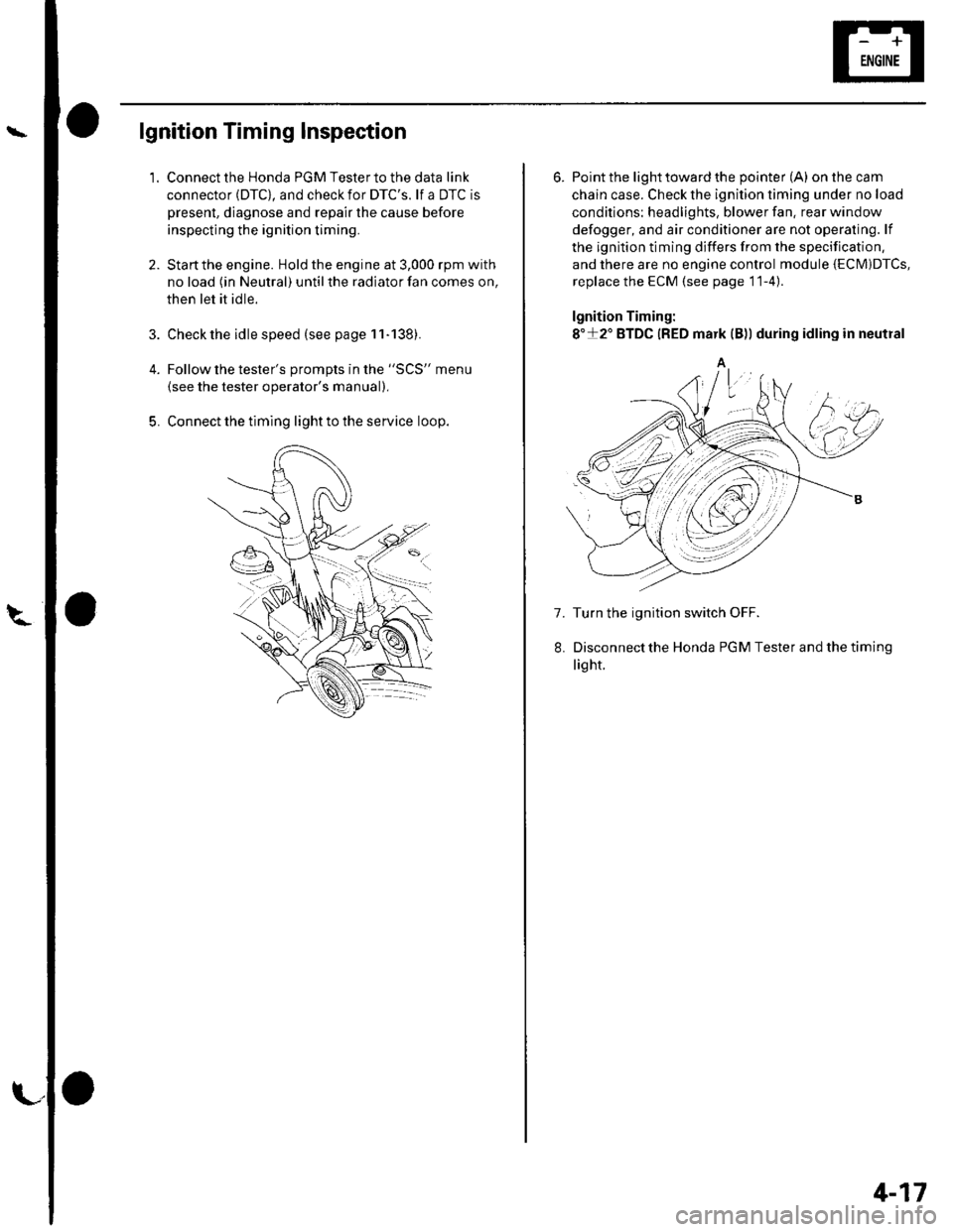
lgnition Timing Inspection
1.
4.
5.
Connect the Honda PGM Tester to the data link
connector (DTC), and check for DTC'S. lf a DTC is
present, diagnose and repair the cause before
inspecting the ignition timing.
Startthe engine. Hold the engine at 3,000 rpm with
no load (in Neutral) until the radiator fan comes on,
then let it idle.
Check the idle speed (see page 11-138).
Follow the tester's prompts in the "SCS" menu
{see the tester operator's manual),
Connect the timing light to the service loop.
o
6. Point the light toward the pointer (A) on the cam
chain case. Check the ignition timing under no load
conditions: headlights, blower fan. rear window
defogger, and air conditioner are not operaling. lf
the ignition timing differs from the specification,
and there are no engine control module {ECM)DTcs,
replace the ECM (see page 11-4)
lgnition Timing:
8"+2" BTDC {RED mark {B)) during idling in neutral
A
7. Turn the ignition switch OFF.
Disconnectthe Honda PGM Tester and thetiming
light.
4-17
Page 59 of 1139

Gharging System
Charging Circuit Troubleshooting (cont'd)
6. Start the engine. Hold the engine at 3,000 rpm with
no load (in Neutral) until the radiator fan comes on,
then let it idle.
7. Raise the engine speed to 2,000 rpm, and hold it
there.
8. Turn the headlights (high beam) on, and measure
voltage at the under-hood fuse/relay box terminal.
ls the voltage between 13.9 and 15.1 v?
YES-Go to step 9.
NO Repair or replace the alternator components
(see page 4-30).1
9. Read the amperage at '13.5 V.
NOTE: Adjust the voltage by turning the blower
motor, rear window defogger, brake lights. etc. ON.
ls the amperage 604 ot morc?
YES-Alternator/regulator operation is OK. I
NO Repair or replace the alternator components(see page 4-30).1
4-24
\,
Alternator Control System Test
NOTE: After troubleshooting, perform the engine
control module (ECM) idle learn procedure (see page
11-139).
1 . Check for proper operation of the electrical load
detector (ELD) by checking the malfunction
indicator lamp (MlL) (see page 1 l-3). lf a DTC is
present, diagnose and repair the cause before
continuing with this test.
2. Disconnect the engine wire harness 6P connector
from the starter sub harness 6P connector.
3. Start the engine, and turn the headlights (high
beam) ON,
4. Measure voltage between the engine wire harness
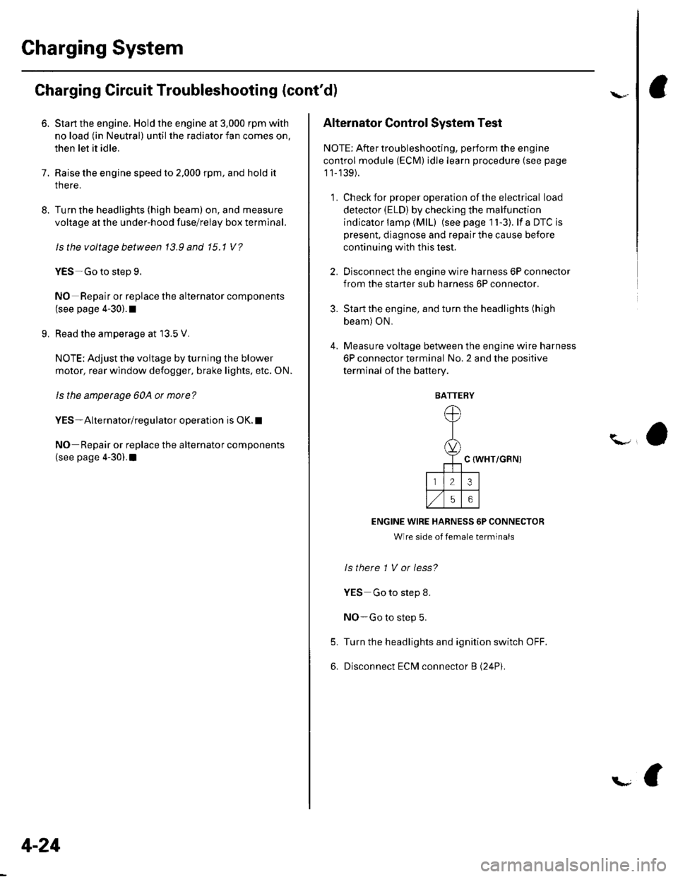
6P connector terminal No. 2 and the positive
terminal of lhe battery.
C {WHT/GRN)
ENGINE WIRE HARNESS 6P CONNECTOR
Wire side of female terminals
ls there 1 V or less?
YES Go to step 8.
NO-Go to step 5.
Turn the headlights and ignition switch OFF.
Disconnect ECM connector B (24P).
5.
6.
BATTERY
Page 341 of 1139

ldle Gontrol System
't.
Alternator FR Signal Circuit Troubleshooting
Disconnect the alternator 4P connector from the
alternalor.
Turn the ignition switch ON {ll).
Measure voltage between ECM connector
terminals 424 and 813.
ECM CONNECTORS
2.
3.
A l31Pl
1 21345611 | 1.,'I
1011112,/56,/r8119l2C21
2312428129130
L(BRN/YEL)
ALTF(WHT
213 4t561
89ltal,/l/15
Wire side of female terminals
ls there about 5 V?
YES Go to step 4.
NO-Go to step 13.
4. Turn the ignition switch OFF.
5. Reconnect the alternator 4P connector.
6. Slan the engine. Hold the engine at 3,000 rpm with
no load (in neutral) until the radiator fan comes on,
then let it idle.
7. lvleasure voltage between ECM connector
terminals A24 and B 13.
Does the voltage decrease when the headlights
and rear window defogger arc tutned on?
YES The alternator FR signal is OK.l
NO-Go to step 8.
8. Turn the ignition switch OFF.
9. Disconnect ECM connector B (24P).
10. Disconnect the alternator 4P connector.
/REDI
11-134
'11. Connect alternator 4P con necto r term inal No.4 to
body ground with a jumper wire.
ALTERNATOR 4P CONNECTOR
12
ALTF34IWHT/RED)
JUMPER WIRE
12.
Wire side of female terminals
Check for continuity between body ground and
EClvl connector terminal 813.
ECM CONNECTOB B (24PI
Wire side of female terminals
ls there continuity?
YES-Testthe alternator (see page 4-22).1
NO Repair open in the wire between the ECM(B 13) and the alternator.l
Turn the ignition switch OFF.
Disconnect ECM connector B (24P).
\
13.
't 4.
Page 500 of 1139

Steering
Steering Wheel Installation
1. Before installing the steering wheel, make sure the
front wheels are aligned straight ahead, then center
the cable reel (A). Do this by first rotating the cable
reel clockwise until it stops. Then rotate it
counterclockwise about two and a half turns. The
arrow mark (B) on the cable reel label should point
straight up.
Position the two tabs (A) of the turn signal
canceling sleeve (B) as shown. Installthe steering
wheel onto the steering column shaft, making sure
the steerlng wheel hub (C) engages the pins (D) of
the cable reel and tabs of the canceling sleeve. Do
not tap on the steering wheel or steering column
shaft when installing the steering wheel.
17-8
3. Install the steering wheel nut (A), and tighten it to
the specified torgue.
A_B39 N.m (4.0 kgf m.29lbt ftl
Connect the cruise control set/resume switch
connector (B). fvlake sure the wire harness is routed
and fastened properly.
Install the driver's airbag, and confirm that the
system is operating properly {see page 23-113).
Check the horn, turn signal canceling and cruise
control switches for proper operation.
Reconnect the battery and do the following:. Do the engine control module (ECM) idle learn
procedure (see page 1l-139),. Power window control unit resetting procedure
\see page 22-1281.. Enter the anti-theft cord for the radio, then enter
the custmer's radio station presets.. Set the clock.
{
7.
lr,',,t
;. _,:!
'' '1i::..'.' l
Page 502 of 1139

Steering
Steering Column Removal
lnstallation
1.
4.
Install the steering column, and make sure the
wires are not caught or pinched by any parts.
Insertthe upper end ofthe steering joint onto the
steering shaft {A) (line up the bolt hole (B) with the
flat portion (C) on the shaft).
8 x 1,25 mm28 N.m{2.9 kgf m,21 rbr.ft)
A
Slip the lower end of the steering joint onto the
pinion shaft {D) (line up the bolt hole with the
groove (E) around the shaft), and loosely lnstallthe
lower joint bolt. Be sure that the lower joint bolt is
securely in the groove in the pinion shaft.
Pull on the steering joint to make su re that the
steering joint is fully seated. Then installthe upper
joint bolt, and tighten it to the specified torque.
Tighten the lower joint bolt to the specified torque.
Finish the installation, and note these items:
. Make sure the wire harness is routed and
fastened properly.
. Make sure the connectors are properly connected.. Reinstallthe steering wheel (see page 17-8).
. Reconnect the battery.- Do the power window control unitreset
procedure {see page 22-128).- Enter the anti-theft code for the radio, then
enter the custmer's radio station presets.
- Set the clock.. Verify horn, turn signal switch, and cruise control
switch operation.. Check wheel alignment, if necessary (see page
18-4).. Do the engine control module (ECM) idle learn
procedu re {see page '11-139).
17-10
and Installation (cont'd){
Page 541 of 1139

EPS Components
(Motor RemovaUlnstallation (cont'dl
lnsiallation
7. Clean the mating surface of the motor (A) and
gearbox.
Apply a thin coat of silicone grease (P/N 08733-
8070E)to the new O-ring (B), and carefully fit it on
the motor.
Apply grease {Nippon Grease WR-S or equivalent
steering gear grease) into the motor shaft (C).
qE
8 x '1.25 mm20 N.m12.0 kgt.m,7 .2lbl ftl
L==-c].E@
9.
17-50
r0.Install the motor on the gearbox by engaging the
motor shaft and worm shaft (D). Note the motor
installation position {direction of motor wires).
Before tightening the bolts, turn the motor two or
three times right and left about 45 degrees. lvlake
sure the motor is evenly seated on the steering
gearbox and that the O-ring is not pinched betlveen
the mating surfaces.
Installthe removed Darts in the reverse order of
removal. and note these items:
lvlake sure the motor 2P connector is properly
connected.
lvlake sure the motor and EPS wires are not
caught or pinched by any parts.
Reconnect the negative cable to the battery.
Do the engine control module (ECM) idle learn
procedure (see page 11-139).
Enter the anti-theft code for the radio station
Dresets. Reset the clock,
Do the oower window control unit reset
procedure (see page 22-1241.
After installation, start the engine, and let it idle.
Turn the steering wheel from lock-to-lock several
times. Check that the EPS indicator does not come
on.
11.
12.
13.
Page 654 of 1139

Body
DoorsComponent Location Index ...........Door Panel Removal/lnstallation .....,..........Door Outer Handle ReplacementDoor Latch ReplacementDoor Glass and RegulatorReplacementDoor Sash Trim Replacement .......................
Door Glass Outer WeatherstripReplacement
Door Weatherstrip Beplacement
Door Glass Adjustment .................................Door Position Adjustment .............................Door Striker Adiustment ................................MirrorsComponent Location Index ...........................Power Mirror Replacement ...........................Mirror Holder Replacement ...........................Rearview Mirror Rep1acement ......................
GlassComponent Location Index ...........................Windshield Replacement
Bear Window Rep1acement ...........................
Ouarter Glass Replacement ..........................MoonroofComponent Location Index ...........................Symptom Troubleshooting Index
Glass Height Adjustment ...............................
Glass ReplacementWind Def lector 8ep1acement ........................Drain Channel Rep1acement ..........................Sunshade Replacement .................................Motor ReplacementFrame and Drain Tube Replacement ............Drain Channel Slider and Cable AssemblyReplacementLimit Switch Adjustment ...............................Closino Force and ODenina Draq Check ......lnterioi TrimComponent Location Index ...........................Trim Removal/lnstallation DoorArea ..........Trim Removal/lnstallation-Rear Side AreaTrim Removal/lnstallation-Cargo Floor AreaTrim Removal/lnstallation-Hatch Area .........Headliner Removal/lnstallation* Carpet Rep1acement .......................................ConsolesConsoles, Front and RearRemova l/lnsta llationFront Console Disassembly/Reassembly .....
20-220,420-620-7
20-920 t0
20- 10
20-1120-1120-1220 13
20-1420-1520-1520-16
20 1120-1920-2520-29
20,3520-3620-3720-3120-3820 3920-4020-4120,42
20 4420-4620,44
20-4920 50
20-51
DashboardInstrument Panel Removal/lnstallation ........Driver's Dashboard Lower CoverRemovat InstallationDriver's Dashboard Under CoverRemova t Insta llation
Oriver's Pocket Removal/lnstallation ............Shift Lever Trim Removal/lnstallation ..........Center Panel Removal/lnstallation ...............Passenger's Dashboard Lower CoverRemova l/lnsta llat ionx Glove Box Removal/lnstallationDashboard Side VentRemoval/lnstallation .................................. 20-64Beverage Holder Removal/lnstallation ........ 20-64Driver'sTray Removal/lnstallation ............... 20-65Passenger's Tray Removal/lnstallation ........ 20 65* Dashboard Removal/lnstallation .................. 20-66Steerinq Hanqer Beam Reolacement ........... 20-68Seats "
Component Location Index ........................... 20-10* Front Seat Removal/lnstallation ................... 20-11* Front Seat Disassembly/Reassembly-Driver's .................................. 20-73* Front Seat Disassembly/Reassembly-Passenger's ........................... 20-74* Front Seat Cover Replacement ..................... 2O-75Rear Seat Removal/1nsta11ation ..................... 20-80Rear Seat-back Latch Replacement .............. 20-81Rear Seat-backStriker Replacement ............ 20-81
20-59
20-59
Rear Seat-back Cover Replacement ............. 20-82Rear Seat Cushion Cover Replacement ....... 20.84BumpersFront Bumper Removal/lnstallation .............Rear Bumoer Removal/lnstallation ...............HoodAdjustmentHood Seal ReplacementHood Insulator Rep1acement .........................Hatch
20-6020,6020 6120-62
20-63
20-63
20,8520-86
20-4720,8820,89
20-5220-5320-5420-55
20-5720-58
Adjustment ................... 20-90Hatch Suppon Strut Replacement ................ 20-91Hatch WeatherstriD Reo1acement ................. 20-92
Fuel Fill DoorAdiustment ................... 20-93Exterior TrimFront Grille Replacement ..............Cowl Covers Replac"rn""t .. . .....................A pillar Corner Trim Replacement ................Roof lMolding Replacement ...........................Rear License Trim ReplacementHatch Spoiler 8ep1acement ...........................Emblem Rep1acement .........................
20-9420-9520-9620-9720,9820-9920-100
Page 656 of 1139

Doors
Component Location Index
POWER WINDOWswtTcH
a
DOOR SASH TRIMReplacement, page 20-10
DOOR GLASS OUTERWEATHERSTRIPReplacement, page 20-10
DOORPosition Adiustment,page 20-12
t
\POWER DOOR LOCK SWITCH(Driver's)
DOOR OUTER TRIM
K-pIJ A'A
dq
W2"'
Ya\J aita.
DOOR WEATHERSTRIPReplacement, page 20-'l'l
20-2