2003 HONDA CIVIC Head
[x] Cancel search: HeadPage 934 of 1139

Roof Antenna Replacement
1. Remove the rear part of headliner (see page 20-54).
2, Disconnect the antenna lead connector (A) and 1P
connector (B) from the roof antenna (C).
3. Remove the mounting nut and the antenna.
22-103
Page 941 of 1139

Moonroof
Moonroof Control Unit Input Test
Remove the headliner (see page 20-54).
Disconnect the 5P connector (A) from the control unit (B).
Wire side offemale terminals
Inspect the connector and socket terminals to be sure they are all making good contact.
. lf the terminals are bent, loose or corroded, repairthem asnecessary. and recheckthe system.. lf the terminals look OK, go to step 4.
IJ
1.
2.
bJ
GRN/WHT LT GRN
12345
RED/YEL BLK
22-110
$J
Page 943 of 1139

Moonroof
Switch Test/Replacement
'1 . Carefully pry the moonroof switch (A) out of the
headlin er.
2. Disconnectthe 5P connector (Blfrom the moonroof
swtrcn.
3. Check for continuity between the terminals in each
switch position according to the table.
Terminal
Pi.iti.. --\145
CLOSEFO
TILT
OPEN-o
lf the continuity is not as specified. replace the
moonroof switch.
4.
22-112
Motor Test
1. Remove the headliner (see page 20-54).
2. Disconnect the 2P connector from the moonroof
motor.
3. Check the motor by connecting power and ground
accordino to the table.
Terminal
pl.iri""---\
OPEN\7o
CLOSE(,
lf the motor does not run. replace it,
NOTE: See closing force check (see page 20-48)for
motor clutch test.
\J
J
Page 944 of 1139

l.
2.
Limit Switch Test
Remove the headliner (see page 20-54).
Disconnect the 4P connector from the moonroof
limit switch.
Check for continuily between the terminals in each
switch position according to the table.
NOTE: Turn the motor by hand with the wrench.
Terminal
Position134
TILTo-o-
OPEN
CLOSE
lf the continuity is not as specified, replace the
moonroof limit switch.
1.
2.
Auto-stop Switch Test
Remove the headliner (see page 20-54).
Disconnect the 2P connector from the moonroof
auto-stop switch.
Check for continuity between the terminals in each
switch position according to the table.
NOTE:. Turn the motor by hand with the wrench,. The auto-stop position is about 145 mm (5.75 in.)
from fully closed.
Position
Terminal12
Botwoen AUTO-STOPand CLOSE
Between OPEN andAUTO.STOP
lf the continuity is not as specified, repair or replace
the auto-stop switch.
22-113
Page 987 of 1139

Keyless/Power Door Lock System
Control Unit Input Test (cont'dl
5. Reconnect all connections to the underdash fuse/relay box, and make these input tests at the appropriate connectors on the under-dashfuse/relay box.
'lfanytestindicatesaproblem,findandcorrectthecause,thenrecheckthesystem.. lf all the inputtests prove OK, goto step 6.
CavitvWireTest conditionTest: Desired resultPossible ca use if result is notobtainedc1'l8LUUnder all conditionsAftach to ground:Parking, side marker, licenseplate lights, and tajllights shouldcome on.
Blown No.2 (15A)fuse in the underhood fuse/relay boxFaulty taillight relayFaulty under-dash fuse/relay boxAn onen in rhc wireBLU/BEOUnder all conditionsAttach to ground:Headlights should come on.Blown No. 15 or 17 (15A)fuse in theunderhood fuse/relay boxFaulty headlight relay '1 or 2An ooen in the wireJ2WHT/REDUnder all conditionsCheck for voltage to ground:There should be battery voltage.Blown No.9 (15A)fuse in the under-hood fuse/relay boxAn oncn in thc wircBLKUnder all conditaonsCheck for voltage to ground:Thcre shouln hc 1 V or lpqsPoor ground (G501)An ooen in the wireJ6OBNUnder allconditionsAttach to ground:The horns should sound.Blown No. 7 (15A)fuse in the underhood fuse/relay boxFaulty horn relayFaulty hornsAn 6nen in rhe wireJ7Under all conditionsCheck for voltage to ground:There should be battery voltage.Elown No. 16 (20A)fuse in the underhood fuse/relay boxAn oocn in ihc wi.cP18BEDHatch openCheck for voltage to ground:There should be 1 V or less.Poor ground (G552)Faulty hatch latch switchAn oncn in rhc wirFHatch closedCheck for voltage to groundlThere shoul.l he 5 V or moreFaulty hatch latch switch
GBNDriver's door openCheck for voltage to g.ound:There should be 1 V or less. Faulty driver's door switch. An ooen in the wireDriver's door closedCheck for voltage to ground:There should be 5 V or more.Faulty driver's door switchShort to oroundo4LT GRN/REDPassenger's door openCheck for voltage to ground:There should be 1 V or less.Faulty passenger's door switchAn ooen inthewirePassenger's door closedCheck for voltage to groundlThere should be sVor more
. Faulty passenger's door switch. Short to oroundX5REDAVHTlgnition key inserted intothe ignition swhchCheck for voltage to ground:There should be 1 V or less.Poor ground {G401)Faulty ignition key switchAn ooen inthewirelgnition key removed fromrhe ionition switchCheck for voltage to ground:There should be 5 V or more.Faulty ignition key switchShort to oroundY1WHT/BLKDriver's door lock knobswitch unlockedCheck for voltage to groundlThere should be 1 V or less.Poorground (G50'l)Faulty driver's door lock knob switchAn open in the wireDriver's door lock knobCheck for voltage to groundlIhere should be 5 V or more.Faulty driver's door lock knob switchShort to oroundY8YEUREDDriver's door lock knobswitch lockedCheck for voltage to groundlThere should be 1 V or less.Poorground (G50'l)Faulty driver's door lock knob switchAn oncn inihewireDriver's door lock knobswitch unlockedCheck for voltage to ground:There should be 5Vor more' Faulty driver's door lock knob sw;tch. Shorr to oroundY10WHT/GRNDrtver's door lock switchunlockedCheck for voltage to groundlThere should be 1 V or less.Poorground (G501iFaulty driver's door lock switchAn ooen in the wireDriver's door lock switch inCheck for voltage to ground:Therc shorl.l be 5V or m6rpFaulty driver's door lock switchShort to o rolrndY12WHT/BLUDriver's door lock switchlockedCheck for voltage to ground:There should be 'l V or less.Poor ground (G501)Faulty driver's door lock switchAn oDen in the wireDriver's door lock switch inCheck tor voltage to ground:There should be 5Vor moreFaulty driver's door lock switch
22-156
J
Page 1002 of 1139

ISystem Descriptions
The Multiplex Control System has four internal
functions:. Multiplexing (send multiple signals over sharedwtres). Wake up/sleep (runs at full power only on demand toreduce battery draw). Fail-safe (fixes or ignores faulty signals). Self-diagnosis (Mode 1 for the system, Mode 2 for
input lines)
The system controls the function of these circuits:. Entry lightcontrol (ignition key lightandceiting light). Wiper/washer intermittent wipe and park functions. Keyless/power door lock. Meter assembly, temperature gauge, and indicator
lights. HVAC (compressor and fan control). Key-in reminder. Headlight reminder. Seatbelt reminder
JI
/ar
22-171
Multiplex Communication
To reduce the number of wire harnesses, digital signals
are sent via shared multiplex communication linesrather than sending normal electrical signals throughindividual wires.. The input signals from each switch are converted todigital signals at the central processing unit (CpU).. The digital signalsaresentfromthetransmitting unitto the receiving unit as serial signals.. The transmitted signal is converted to a switch signalat the receiving unit, and it operates the related
component or monitors a swltch.. There are exclusive communicalion lines between
the ECM, the gauge assembly, and the under,dash
fuse/relay box.
Wake-up and Sleep
The multiplex control system has "wake-up" and"sleep" functions to decrease parasitic draw on the
battery when the ignition switch is OFF.. ln the sleep mode, the multiplex control unit stops
functioning (communication and CPU control) when it
is not necessary for the system to operate.. As soon as any operation is requested (for example, adoor is unlocked), the related control unit in the sleep
mode immediately wakes up and begins to function.. When the ignition switch is turned OFF, and the
driver's or front passenger's door is opened, then
closed, there is about a 10 second delay before the
control unit goes from the wake-up mode to the sleepmode.. lf any door is open, the sleep mode will not function.. lf a key is in the ignition switch, the sleep mode will
not function.. When in sleep mode, the draw is reduced from
70 80 mA to less than 10 mA.
Fail-safe
To prevent improper operation, the multiplex controlsystem has a fail-safe function. In the fail-safe mode,
the output signal js fixed when any part of the systemmalfunctions (for example a faulty control unit orcommunication line).
Each control unit has a hardware fail-safe function thatfixes the output signal when there is any CPUmalfunction, and a software fail-safe function thatignores the signal from the malfunctioning control unitand allows the system to operate normally.
Page 1019 of 1139

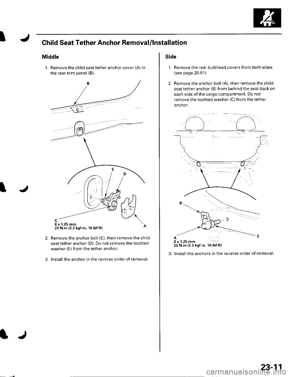
IChild Seat Tether Anchor RemovaUlnstallation
Middle
1. Remove the child seat tether anchor cover (A) in
the rear trim panel (B).
8 x 1.25 mm22 N m {2.2 ksf.m, 16lbf.ft)
,tltl
v\
2.
3.
Remove the anchor bolt (C), then remove the child
seat tether anchor (D). Do not remove the toothed
washer (E) from the tether anchor.
Installthe anchor in the reverse order of removal.
IJ
23-11
Side
1. Remove the rear bulkhead covers from both sides
(see page 20-51).
2. Remove the anchor bolt (A), then remove the child
seat tether anchor (B) from behind the seat-back on
each side ofthe cargo compartment. Do not
remove the toothed washer (C) from the tether
anchor.
AI18 x 1.25 mm22 N.m {2.2 kgt m. 16lbfft)
lnstallthe anchors in the reverse order of removal.
f-..- t".i..].-
Page 1039 of 1139

sRs
System Description (cont'dl
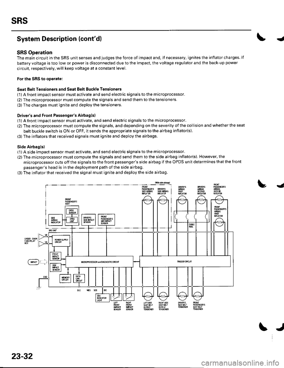
SRS Operation
The main circuit in the SRS unit senses and judges the force of impact and, if necessary. ignites the inflator charges. lf
battery voltage is too low or power is disconnected due to the impact, the voltage regulator and the back-up power
circuit, respectively, will keep voltage at a constant level.
For the SRS to operate:
Seat Belt Tensioners and Seat Belt Buckle Tensioners
(1) A front impact sensor must activate and send electric signals to the microprocessor.
(2) The microprocessor must compute the signals and send them to the tensioners.
(3) The charges must ignite and deploy the tensioners.
Driver's and Front Passenger's Airbagls)
(1) A front impact sensor musl activate. and send electric signals to the microprocessor.
(2) The microprocessor must compute the signals. and depending on the severity of the collision and whether the seat
belt buckle swilch is ON or OFF, it sends the appropriate signals to the airbag inflator(s).
(3) The inflators that received signals must ignite and deploy the airbags.
Side Airbaglsl( 1) A side impact sensor must activate, and send electric signals to the microprocessor.
(2) The microprocessor must compute the signals and send them to the side airbag inflator(s). However, the
microprocessor cuts off the signals to the front passenger's side airbag if the OPDS unit determines that the tront
passenger's head is in the deployment path of the side airbag.
(3) The inflator that received the signal must ignite and deploy the side airbag.
lw$ad..n sl
!J
T'sEcttoJn0mP gsfrlctR S oXrVEr S I9oEAiA$ SOtlr&G I
f'**)r !
23-32
\J