2003 HONDA CIVIC Head
[x] Cancel search: HeadPage 736 of 1139

Seats
Rear Seat-back Cover Replacement
NOTE:. Take care not to tear the seams or damage the seat
covers.. Put on gloves to protect your hands.
'1. Remove the seat-back (see page 20-80).
Remove the headrest.
Pull up the latch cover (A) to telease the clips. then
remove it.
Fastener Locations
) : Clip, 4
1W
4.Pull up the outside edge of the latch lever cover (A)
to release the clips, and release the cover from thepivot pins (B) ofthe latch lever {C) while pulljng the
latch lever.
Fastener Locations
D : Clip, 2
i
*rJ
20-82
5. On right seat-backi Using a Torx T30 bit, remove
the bolts, then remove the belt holder trim (A), and
remove the trim from the center belt (B).
Fastener
) : Bolt,
A*-\./-
Locations6x1.0mm9.8Nm(1.0 kgf.m,7.2 lbf.ft)
Release the hook (A), and unzip the seat-back cover(B). The right seat-back is shown. the left seat-back
is similar.
\
Page 737 of 1139

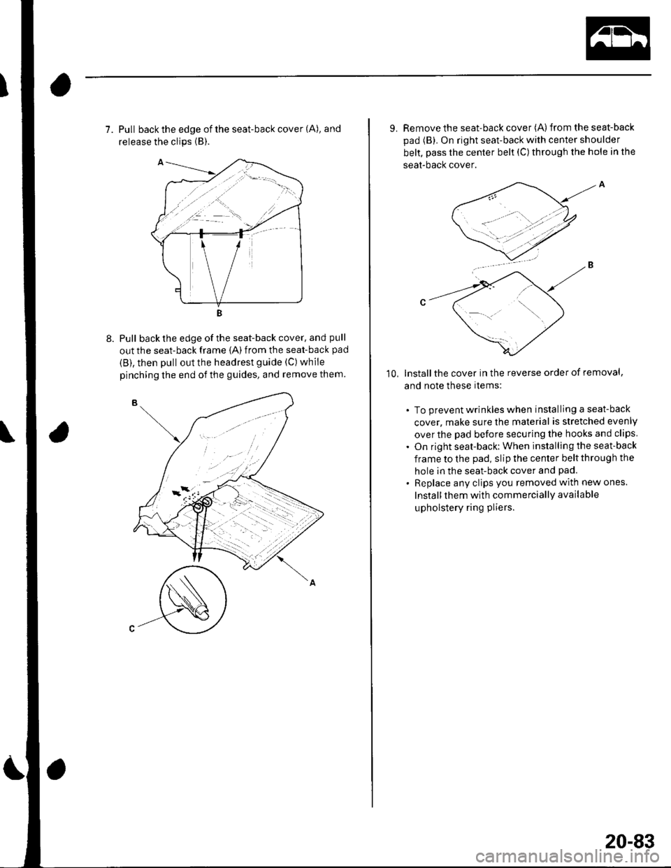
7. Pull back the edge of the seat-back cover (A), and
release the clips {B).
Pull back the edge of the seat-back cover, and pull
out the seat-back frame {A) from the seat-back pad
{B), then pull out the headrest guide (C) while
pinching the end of the guides, and remove them.
9. Remove the seat-back cover (A)from the seat-back
pad (B). On right seat-back with center shoulder
belt, pass the center belt (C) through the hole in the
seat-bacl( cover.
lnstallthe cover in the reverse order of removal,
and note these items:
. To prevent wrinkles when installing a seat-back
cover, make sure the material is stretched evenly
over the pad before securing the hooks and clips
. On right seat-back: When installing the seat-back
frame to the pad, slip the center belt through the
hole in the seat-back cover and pad.
. Replace any clips you removed with new ones.
Install them with commercially available
upholstery ring pliers.
10,
20-83
Page 744 of 1139

Hatch
Adjustment
1. Remove the support strut from each side (see page 20-91).
2. RemovetheC-pillartrimfromeachside(seepage20-5'l),andpull downtherearponionoftheheadliner(seepage 20-54). Take care not to bend the headliner excessively.
3. Remove the rear trim panel (see page 20-52).
4, Slightly loosen each bolt and nut.
5. Adjustthe hatch (A) alignment in the following sequence.
. Adjustthe hatch hinges (B) right and left, as well as forward and rearward, using th e elongated holes.'Turnthehatchedgecushions(C),inoroutasnecessary,tomakethehatch(D).fitflushwiththebodyattheside
edges.. Adjust the fit between the hatch and hatch opening by moving the striker (D).
8 x 1.25 mm18 N.m 11.8 kgf.m, 13 lbf.ft)
\
8 x 1.25 mm22 N.m{2.2 kgf.m, 16 lbf.ft}
20-90
Page 831 of 1139

\Body Electrical
Body ElectricalSpecialToolsGeneral Troubleshooting tntorrnaiion.'......
Relay and Control Unit Locations .....
Connectors and Harnesses
Fuse/Relay Boxes ...............................
Power Distribution .............................
Ground Distribution ...........................
Under-dash Fuse/Relay Box ..............
Battery ..............
Relays ................
*lgnition Switch ..............
*Gauges
Component Location Index .......................Self-diagnostic Procedure ..........................Circuit DiagramGauge Bulb Replacement ..........................Gauge Assembly ReplacementCoolant Temperature
Gauge Troubleshooting .... ....................Vehicle Speed Signal CircuitTroubleshootingVSS Replacement
Exterior LightsComponent Location Index .......................Circuit DiagramDaytime Running Lights ControiUnit Input Test (Canada) ........................Headlight Ad,ustment .................. .. .....Headlighr Replacement ..............................Combination Light SwitchTest/ReplacementBulb ReplacementTaillight Replacement ..........................High Mount Brake Light Replacement ......License Plate Light Replacement ..............Side Marker Light Replacement ................Brake Pedal Position Switch Test ..............Side Turn Signal Light Replacement ........
Turn Signal/HazardFlasher SystemComponent Location Index .......................Circuit DiagramTurn Signal/Hazard Relay lnputTest ........Hazard Warning Switch Test
22,3
22-7
22-13
22-44
22-46
22-4A
22-49
22-50
22-51
22-53
22-5422-5622-5422 6322-64
22-64
22-6522 61
22-6822--71
22-7 622-7422-79
22-AO22-4122-8222-4222-4322-4322-4422-84
22-8�522 A622-8722-88
22-10422-105
22-10622-107
Entry Lights control systemComponent Location Index ....................... 22-89Circuit Diagram ......... 22 90lgnition Key Switch Test .....................,...... 22-9'llgnition Key Light Test ............................... 22-91Control Unit Input Test ..........,.................... 22 92
Interior LightsComponent Location Index ....................... 22-94Circuit Diagram ......... 22-95Ceiling LighVSpotlightsTesVReplacement ................................... 22-96Rear Ceiling Light TesVReplacem ent ........ 22-96Cargo Area Light Test/Replacem ent ......... 22-97Hatch Latch Switch Test ..,..,....................... 22-97
*Audio SystemComponent Location Index ....................... 22-98Circuit Diagram ......... 22,99Audio Unit Removal/lnstallation ............... 22-1OOAudio Unit Connector Replacement ......... 22-101Speaker Replacement ................................ 22-102Roof Antenna Rep1acement ....................-.. 22-103
Rear Window DefoggerComponent Location Index ...........Circuit Diasram .. ....... .. ..... ....... ...:::::.::.::.Function TestDefogger Wire Repair .................................Noise Condenser CapacityTest ................
MoonroofComponent Location Index ....................... 22-1OBCircuit Diagram ......... 22-109Moonroof Control Unit Input Test ............. 22-'l10Switch TesVReplacement ........,.....,........... 22-1 12Motor Test ................. 22-112Limit Swilch Test ...... 22-'l'13Auto-stop Switch Test ................................ 22-1 13
Power MirrorsComponent Location Index ....................... 22-114Circuit Diagram ......... 22-115Function Test ............. 22-116Power Mirror Switch Test .......................... 22-ll7Power Mirror Actuator Test ....................... 22-117Power Mirror Actuator Replacement ........ 22-11A
* HornsComponent Location Index ....................... 22-120Circuit Diagram ......... 22-121Horn TesVReplacement ...........................-. 22-122Horn Switch Test .,.... 22-122
\
Page 849 of 1139

Connectors and Harnesses
Connector to Harness Index {cont'dl
Engine Compartment Wire Harness (Right branch)
\
Connsctor or TerminalCavitissLocationConnects toNotesABS modulator-control unitBearwasher motorRight front ABS wheel sensorRight front airbag s€nsorBightfront parking lightRight front side marker lightRight front turn signal lightRight headlightRight hornwash€rfluid level switchWindshield washer motor
812
110112
7
222222
I22
Bight side o{ engine compartmentBehind right side of {ront bumperRight side ot engine compartmentBehind right side of front bumperBehind right headlightBehind rightside of Jront bumperBehind right headlightBehind right headlightBehind front bumperBehind rightside of tront bumperBehind rioht side of front bumoerCanada
G202
G2016Behind rightside of tront bumper
Behind rightside of Jront bumper
Body ground via €nginecompartment wtre harnessBody ground via engine.omnerhent wire harness
22-18
Page 851 of 1139

Connectors and Harnesses
Engine Compartment Wire Harness (Left branch)
AirJuel (A,,/F) ratio sensorBrake fluid level switchCondenser fan motorCruise control actuatorELD unitFog light connectorLeft front ABS wheel sensorLeft front airbag sensorLeft front parking lightLeft front side marker lightLeft lrontturn signal lightLeft headlightLeft hornRadiator fan motorRadiator fan switchSecondary heated oxygen (SHO2S)
Test tachometer connectorWindshield wiper motorUnder'hood fuse/relay boxconnector A {see page 22-44)Under-hood f use/relay boxconnector B (see page 22-44)Under hood fuse/relay boxconnector C (see page 22-44)Under hood fuse/relay boxconnector D (see page 22 44)Under-hood fuse/relay box
Front of engine companmentLeft side of engine compartmentLeft side of engine compartmentLeft side o{ engine compartmentFront of engine compartmentUnder right side of cowl coverUnder'hood f use/relay boxLeft side of engine compartmentLeft side of engine companmentBehind left side of front bumperBehind left headlightBehind left side of front bumperEehind left headlightBehind left headlightBehind front bumperLeft side of engine compartmentFront of engine compartmentLeft side of engine compartment
Left side of engine companmentL.Jnder left side of cowl coverL.Jnder hood fuse/relay box
L.Jnder hood fuse/relay box
L.Jnder'hood f use/relay box
underhood fuse/relay box
Under-hood fuse/relay box
24222
2519
12
17
13202123
3
117
I
10
5
6
l2
2243,l
222223l224
252
5
12
Connector to Harness Index (cont'dl
\
22-20
Page 875 of 1139

Fuse/Relay Boxes
Connector to Fuse/Relay Box Index
Under-hood Fuse/Relay Box
lview of tront sidel
- a-------) | | T---r .-:-tt || tL__.1 | I
------tttL""tt tt ttL lL ltl'".-
{View of back side)
SocketRefTerminalConnects to
Ay'C compressor clutch relay
B
Blower motor relay
c
Condenser fan relay
D
E
ELD unit
Headlight relay 1
Headlight relay 2
Horn relay
Radiator fan relay
Rear window defoqqer relay
14
2
15
91'
11
to
5
6
10'l
J
2
4
5
4
4
14
7
3
4
4
4
4
Engine compartment wire harness (see page 22-18)
Engine compartment wire harness (see page 22-18)
Engine compartment wire harness (see page 22-18)
Engine compartment wire harness (see page 22-18)
Engine compartment wire harness (see page 22-18)
Engine compartment wire harness {see page 22-18)
T1 (Batterv)8Starter subharness (see oaqe 22-15)
T101 (Alternator)7Starter subharness {see oaoe 22-'15}
""""-l- tr -l T _l T Il
I tTt Tr,/^-------lFrr^l -/1-l sz- l:!)L' lrt
22-44
Page 877 of 1139

Power Distribution
Fuse to Components lndex
Under-hood Fuse/Relay Box
Fuse
Number
AmpsWire ColorComponent(sl or Circuit(s) Protected
'I204BLUI/ELCondenser fan motor
BLU/REDAy'C compressor clutch
15AWHT/GRNDash lights, Front parking lights, Front side marker lights, License plate
liqht, Rear side marker liqhts, Tailliqhts
7.5AWHT/BLUCarqo area liqht, Ceilinq liqhts. lqnition Kev liqht. Sootliohts
204BLU/BLKRadiator fan motor
510AWHT/BLKTurn siqnal/hazard relav, Turn siqnal liqhts
15AWHT/BLKCKP sensor, ECM, IAC valve, lmmobilizer control unit-receiver, Injectors,
PGM-FI main relav 1 and 2. TDC sensor
715AWHT/GRNBrake lights, Brake signals (to ABS modulator-control unit, Cruise control
unit, ECM)
BLU/REDi1 Orns
820AWHT/GRNABS modulatorcontrol unit
910AWHT/REDAudio unit, Data link connector (DLC), Gauge assembly, lmmobilizer
control unit-receiver, lmmobilizer indicator light. Keyless receiver unil,
lvlultiDlex control unit
1040AWHT/REDABS modulator-control unit
1130AB LK/YE LNoise condenser, Rear window defoqqer
40ABLU^^/HTBlower motor
IJ40AWHT/BLKNo. 7 fuse (in the under-dash fuse/relav box), Power window relav
1440AWHT/REDNo.2 and No.3 fuses (in the under-dash fuse/relav box)
t515AREDI/ELDaytime running lights control unit (Canada), Daytime running lights relay
{Canada), Hioh beam indicator liqht. Left headliqht
16204WHTMultiplex control unit
1715AREDDavtime runninq liqhts control unit (Canada). Rioht headlioht
1860AWHTiBLUEPS control unit
1980ABatterv. Power distribution
2040A'
50A'?
WHTlgnition switch (BAT)
* 1: USA" 2. Canada
O: Spare fuse
t t"| lll Itt 4t I
l l---- E'l E,l E,l r--r r---r t__J i; i6'!/'
E,l E,l E,l Eol E l f__--lI l'lr]n | |I r L__J,a ,..r^{-------l^-,
n[:]$"Lrt " N2, nf - r^l
22-46