Page 135 of 240
brake pedal pulsation may be observed during ABS braking; any
pulsations or mechanical noise you may feel or hear is normal.
ABS warning lamp
ABS
TheABSlamp in the instrument cluster momentarily illuminates when
the ignition is turned to ON. If the light does not illuminate during start
up, remains on or flashes, the ABS may be disabled and the ABS may
need to be serviced.
Even when the ABS is disabled,
normal braking is still effective. (If
your BRAKE warning lamp
illuminates with the parking brake
released, have your brake system serviced immediately.)
Using ABS
When hard braking is required, apply continuous force on the brake
pedal; do not pump the brake pedal since this will reduce the
effectiveness of the ABS and will increase your vehicle’s stopping
distance. The ABS will be activated immediately, allowing you to retain
full steering control during hard braking and on slippery surfaces.
However, the ABS does not decrease stopping distance.
Parking brake
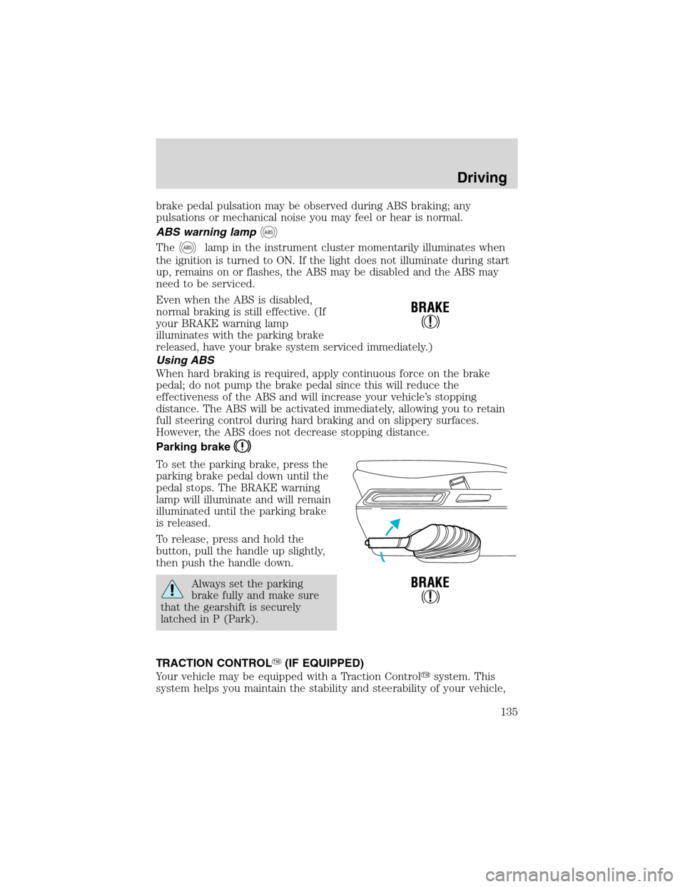
To set the parking brake, press the
parking brake pedal down until the
pedal stops. The BRAKE warning
lamp will illuminate and will remain
illuminated until the parking brake
is released.
To release, press and hold the
button, pull the handle up slightly,
then push the handle down.
Always set the parking
brake fully and make sure
that the gearshift is securely
latched in P (Park).
TRACTION CONTROL�(IF EQUIPPED)
Your vehicle may be equipped with a Traction Control�system. This
system helps you maintain the stability and steerability of your vehicle,
Driving
135
Page 138 of 240
•A slight deceleration of the vehicle
•The TRAC ACTIVE indicator light will illuminate
•If your foot is on the brake pedal, you will feel a vibration in the
pedal.
•If the driving condition is severe and your foot is not on the brake, the
brake pedal will move to apply higher brake forces. You may also hear
a whoosh of air from under the instrument panel during this severe
condition.
All these conditions are normal during AdvanceTrac�operation.
Do not alter or modify your vehicle’s suspension or steering; the
resulting changes to the vehicle’s handling can adversely affect
the AdvanceTrac�system. Also, do not install a stereo
loudspeaker near the front center console or under either front
seat. The speaker vibrations can adversely affect the
AdvanceTrac�sensors located in this area.
Aggressive driving in any road conditions can cause you to lose
control of your vehicle increasing the risk of severe personal
injury or property damage. The occurrence of an AdvanceTrac�event
is an indication that at least some of the tires have exceeded their
ability to grip the road; this may lead to an increased risk of loss of
vehicle control, vehicle rollover, personal injury and death. If you
experience a severe road event, SLOW DOWN.
STEERING
To prevent damage to the power steering system:
•Never hold the steering wheel at its furthest turning points (until it
stops) for more than a few seconds when the engine is running.
•Do not operate the vehicle with a low power steering pump fluid level
(below the MIN mark on the reservoir).
If the power steering system breaks down (or if the engine is turned
off), you can steer the vehicle manually, but it takes more effort.
If the steering wanders or pulls, check for:
•an underinflated tire
•uneven tire wear
•loose or worn suspension
components•loose or worn steering
components
•improper steering alignment
Driving
138
Page 151 of 240
Canadian customers who require roadside assistance, call
1–800–665–2006.
If you need to arrange roadside assistance for yourself, Ford Motor
Company will reimburse a reasonable amount. To obtain reimbursement
information, U.S. Ford or Mercury vehicles customers call
1-800-241-3673; Lincoln vehicle customers call 1–800–521–4140.
Canadian customers who need to obtain reimbursement information, call
1–800–665–2006.
ROADSIDE COVERAGE BEYOND BASIC WARRANTY
In the United States, you may purchase additional roadside assistance
coverage beyond this period through the Ford Auto Club by contacting
your Ford or Lincoln Mercury dealer.
Similarly in Canada, for uninterrupted Roadside Assistance coverage, you
may purchase extended coverage prior to your Basic Warranty’s Roadside
Assistance expiring. For more information and enrollment, contact
1–877–294–2582 or visit our website at www.ford.ca.
HAZARD FLASHER
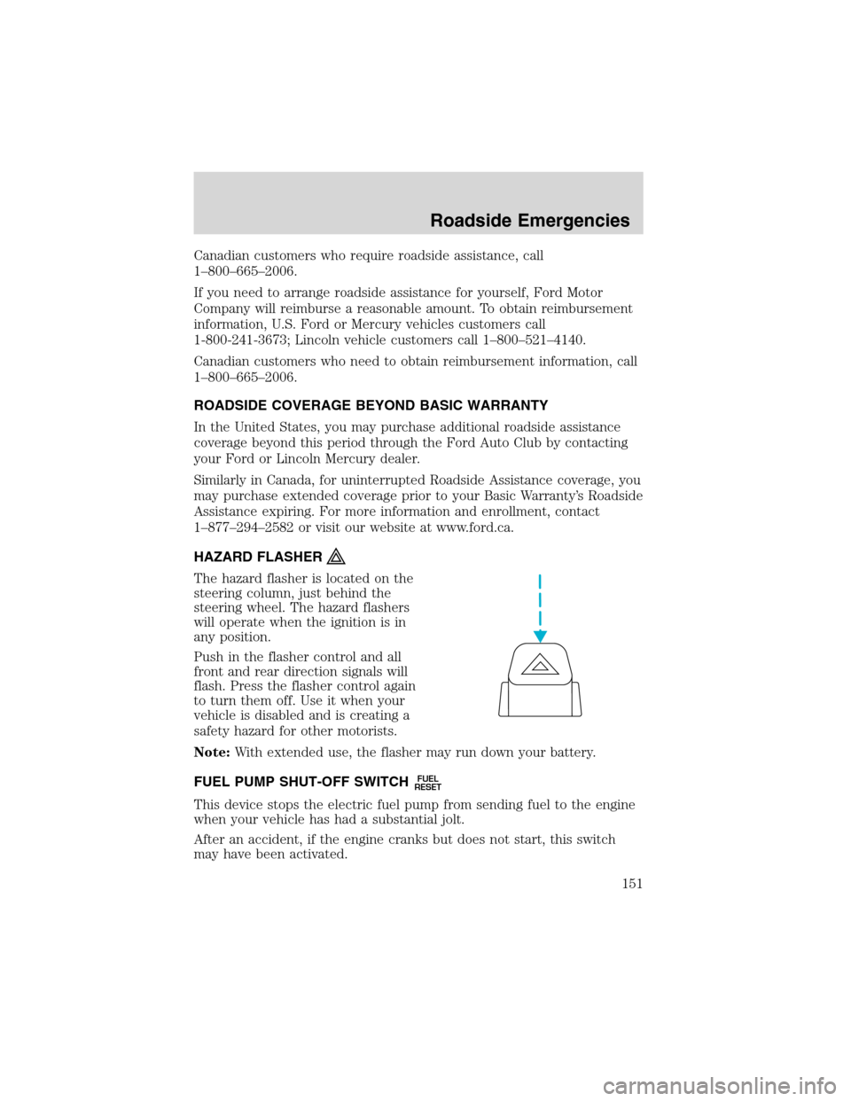
The hazard flasher is located on the
steering column, just behind the
steering wheel. The hazard flashers
will operate when the ignition is in
any position.
Push in the flasher control and all
front and rear direction signals will
flash. Press the flasher control again
to turn them off. Use it when your
vehicle is disabled and is creating a
safety hazard for other motorists.
Note:With extended use, the flasher may run down your battery.
FUEL PUMP SHUT-OFF SWITCH
FUEL
RESET
This device stops the electric fuel pump from sending fuel to the engine
when your vehicle has had a substantial jolt.
After an accident, if the engine cranks but does not start, this switch
may have been activated.
Roadside Emergencies
151
Page 153 of 240
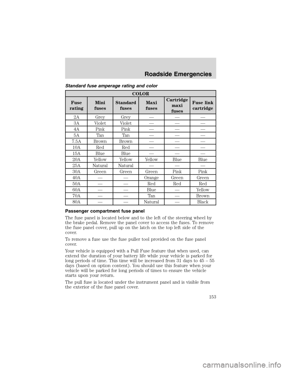
Standard fuse amperage rating and color
COLOR
Fuse
ratingMini
fusesStandard
fusesMaxi
fusesCartridge
maxi
fusesFuse link
cartridge
2A Grey Grey———
3A Violet Violet———
4A Pink Pink———
5A Tan Tan———
7.5A Brown Brown———
10A Red Red———
15A Blue Blue———
20A Yellow Yellow Yellow Blue Blue
25A Natural Natural———
30A Green Green Green Pink Pink
40A——Orange Green Green
50A——Red Red Red
60A——Blue—Yellow
70A——Ta n—Brown
80A——Natural—Black
Passenger compartment fuse panel
The fuse panel is located below and to the left of the steering wheel by
the brake pedal. Remove the panel cover to access the fuses. To remove
the fuse panel cover, pull up on the latch on the top left side of the
cover.
To remove a fuse use the fuse puller tool provided on the fuse panel
cover.
Your vehicle is equipped with a Pull Fuse feature that when used, can
extend the duration of your battery life while your vehicle is parked for
long periods of time. This time will be increased from 31 days to 45–55
days (based on option content). You should use this feature when your
vehicle will be parked for long periods of times to ensure the vehicle
starts upon your return.
The pull fuse is located under the instrument panel and is visible from
the exterior of the fuse panel cover.
Roadside Emergencies
153
Page 155 of 240
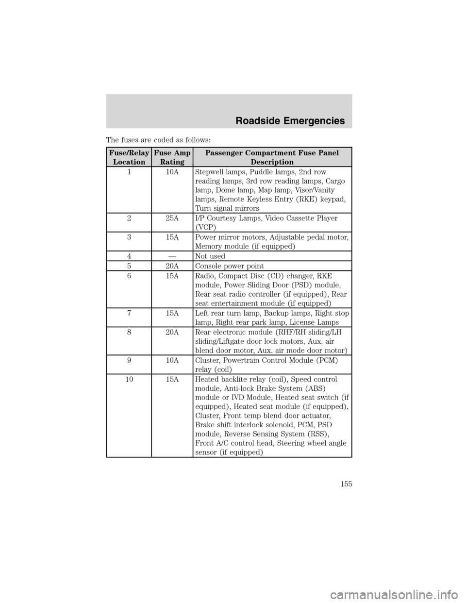
The fuses are coded as follows:
Fuse/Relay
LocationFuse Amp
RatingPassenger Compartment Fuse Panel
Description
1 10A Stepwell lamps, Puddle lamps, 2nd row
reading lamps, 3rd row reading lamps, Cargo
lamp, Dome lamp, Map lamp, Visor/Vanity
lamps, Remote Keyless Entry (RKE) keypad,
Turn signal mirrors
2 25A I/P Courtesy Lamps, Video Cassette Player
(VCP)
3 15A Power mirror motors, Adjustable pedal motor,
Memory module (if equipped)
4—Not used
5 20A Console power point
6 15A Radio, Compact Disc (CD) changer, RKE
module, Power Sliding Door (PSD) module,
Rear seat radio controller (if equipped), Rear
seat entertainment module (if equipped)
7 15A Left rear turn lamp, Backup lamps, Right stop
lamp, Right rear park lamp, License Lamps
8 20A Rear electronic module (RHF/RH sliding/LH
sliding/Liftgate door lock motors, Aux. air
blend door motor, Aux. air mode door motor)
9 10A Cluster, Powertrain Control Module (PCM)
relay (coil)
10 15A Heated backlite relay (coil), Speed control
module, Anti-lock Brake System (ABS)
module or IVD Module, Heated seat switch (if
equipped), Heated seat module (if equipped),
Cluster, Front temp blend door actuator,
Brake shift interlock solenoid, PCM, PSD
module, Reverse Sensing System (RSS),
Front A/C control head, Steering wheel angle
sensor (if equipped)
Roadside Emergencies
155
Page 160 of 240
Fuse/Relay
LocationFuse Amp
RatingPower Distribution Box Description
117 40A** Auxiliary blower relay coil, Auxiliary blower
motor
118 50A** Left-hand PSD module
119 30A** Fuse junction box bus #1
120 40A** Front blower relay coil, Front blower motor
121 20A** Ignition switch, Rear defrost relay coil
122 40A** Right-hand power seat motors, Right-hand
power lumbar motor
201—Not used
202—Front wiper ON/OFF relay
203—Rear wiper relay
204—A/C clutch relay
205—Horn relay
206—Not used
207—Fuel pump relay
208—Not used
209—Front wiper HI/LO relay
301—Starter interrupt relay
302—High-speed engine cooling fan relay
303—Low-speed engine cooling fan relay
304—PCM Relay
401—Not used
501—PCM diode
502—Not used
503—Not used
* Mini Fuses ** Maxi Fuses
CHANGING A FLAT TIRE
If you get a flat tire while driving:
•do not brake heavily.
•gradually decrease the vehicle’s speed.
•hold the steering wheel firmly.
•slowly move to a safe place on the side of the road.
Roadside Emergencies
160
Page 185 of 240
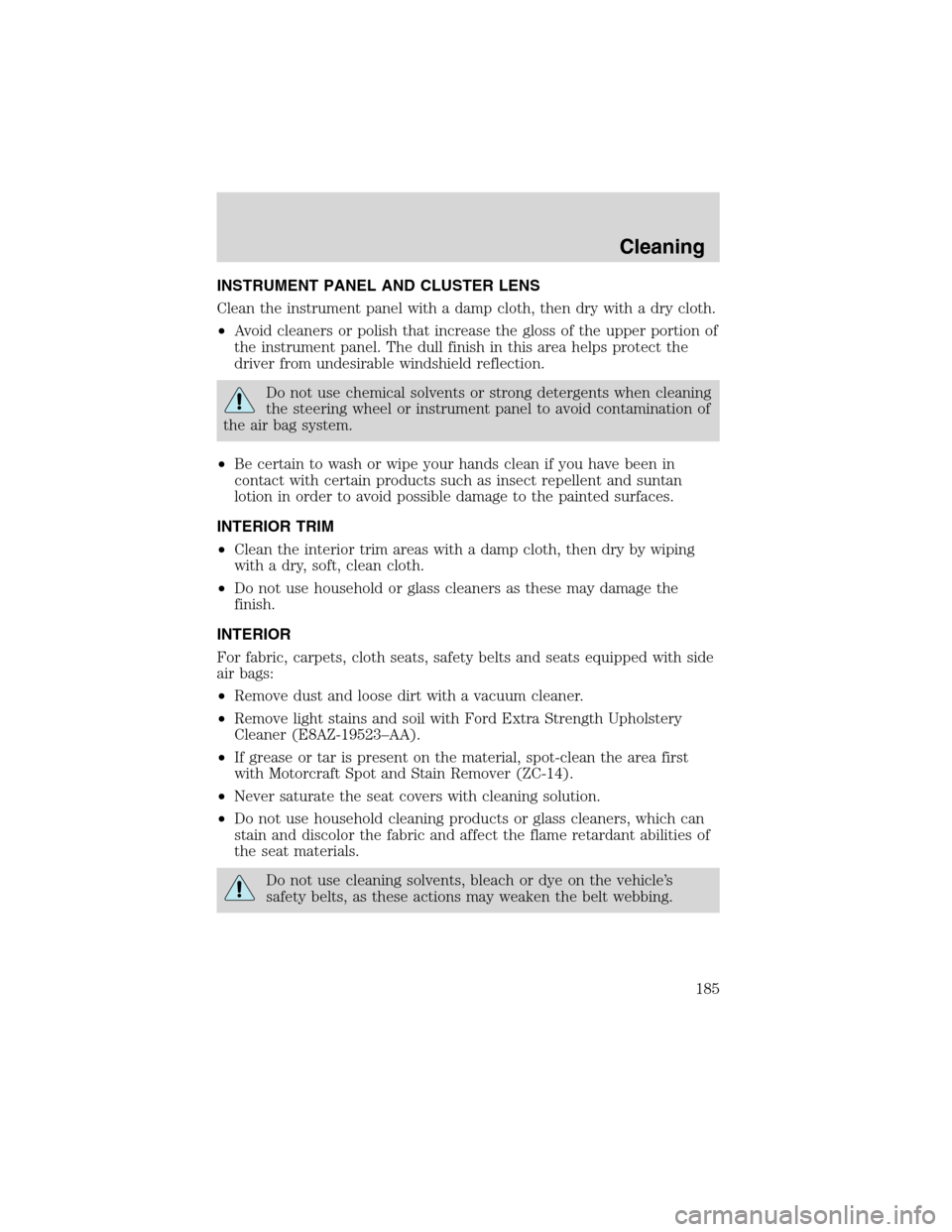
INSTRUMENT PANEL AND CLUSTER LENS
Clean the instrument panel with a damp cloth, then dry with a dry cloth.
•Avoid cleaners or polish that increase the gloss of the upper portion of
the instrument panel. The dull finish in this area helps protect the
driver from undesirable windshield reflection.
Do not use chemical solvents or strong detergents when cleaning
the steering wheel or instrument panel to avoid contamination of
the air bag system.
•Be certain to wash or wipe your hands clean if you have been in
contact with certain products such as insect repellent and suntan
lotion in order to avoid possible damage to the painted surfaces.
INTERIOR TRIM
•Clean the interior trim areas with a damp cloth, then dry by wiping
with a dry, soft, clean cloth.
•Do not use household or glass cleaners as these may damage the
finish.
INTERIOR
For fabric, carpets, cloth seats, safety belts and seats equipped with side
air bags:
•Remove dust and loose dirt with a vacuum cleaner.
•Remove light stains and soil with Ford Extra Strength Upholstery
Cleaner (E8AZ-19523–AA).
•If grease or tar is present on the material, spot-clean the area first
with Motorcraft Spot and Stain Remover (ZC-14).
•Never saturate the seat covers with cleaning solution.
•Do not use household cleaning products or glass cleaners, which can
stain and discolor the fabric and affect the flame retardant abilities of
the seat materials.
Do not use cleaning solvents, bleach or dye on the vehicle’s
safety belts, as these actions may weaken the belt webbing.
Cleaning
185
Page 190 of 240
IDENTIFYING COMPONENTS IN THE ENGINE COMPARTMENT
3.8L OHV V6 engine
1. Brake fluid reservoir
2. Air filter assembly
3. Power distribution box
4. Battery
5. Automatic transmission fluid dipstick
6. Engine oil dipstick
7. Engine oil filler cap
8. Windshield washer fluid reservoir
9. Engine coolant reservoir
10. Power steering fluid reservoir
345678
91012
Maintenance and Specifications
190