Page 40 of 240
BULBS
Replacing exterior bulbs
Check the operation of all the bulbs frequently.
Using the right bulbs
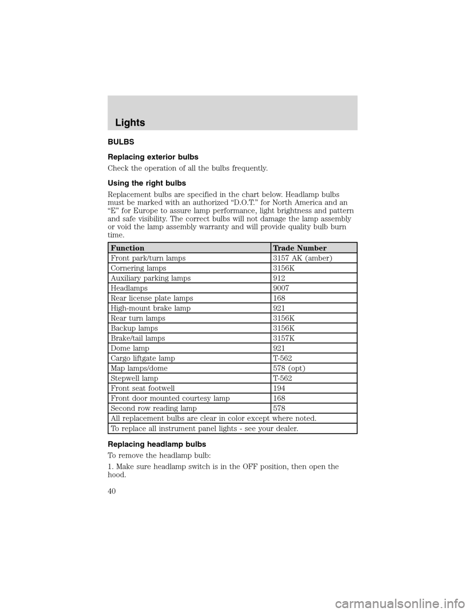
Replacement bulbs are specified in the chart below. Headlamp bulbs
must be marked with an authorized“D.O.T.”for North America and an
“E”for Europe to assure lamp performance, light brightness and pattern
and safe visibility. The correct bulbs will not damage the lamp assembly
or void the lamp assembly warranty and will provide quality bulb burn
time.
Function Trade Number
Front park/turn lamps 3157 AK (amber)
Cornering lamps 3156K
Auxiliary parking lamps 912
Headlamps 9007
Rear license plate lamps 168
High-mount brake lamp 921
Rear turn lamps 3156K
Backup lamps 3156K
Brake/tail lamps 3157K
Dome lamp 921
Cargo liftgate lamp T-562
Map lamps/dome 578 (opt)
Stepwell lamp T-562
Front seat footwell 194
Front door mounted courtesy lamp 168
Second row reading lamp 578
All replacement bulbs are clear in color except where noted.
To replace all instrument panel lights - see your dealer.
Replacing headlamp bulbs
To remove the headlamp bulb:
1. Make sure headlamp switch is in the OFF position, then open the
hood.
Lights
40
Page 90 of 240
Memory seats/rearview mirrors/adjustable pedals (if equipped)
This system allows automatic
positioning of the driver seat,
outside rearview mirrors, and
adjustable pedals to two
programmable positions.
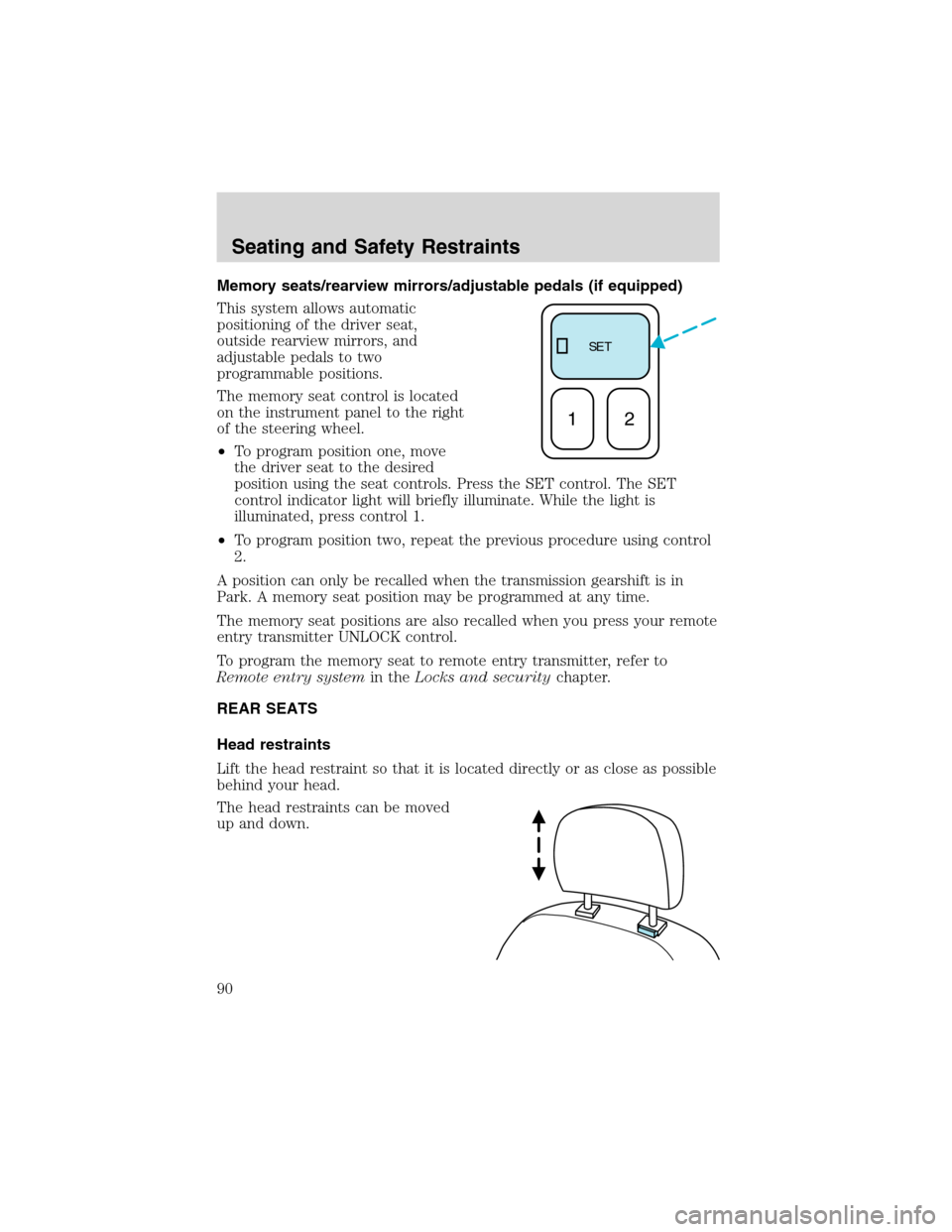
The memory seat control is located
on the instrument panel to the right
of the steering wheel.
•To program position one, move
the driver seat to the desired
position using the seat controls. Press the SET control. The SET
control indicator light will briefly illuminate. While the light is
illuminated, press control 1.
•To program position two, repeat the previous procedure using control
2.
A position can only be recalled when the transmission gearshift is in
Park. A memory seat position may be programmed at any time.
The memory seat positions are also recalled when you press your remote
entry transmitter UNLOCK control.
To program the memory seat to remote entry transmitter, refer to
Remote entry systemin theLocks and securitychapter.
REAR SEATS
Head restraints
Lift the head restraint so that it is located directly or as close as possible
behind your head.
The head restraints can be moved
up and down.
SE T
12
Seating and Safety Restraints
90
Page 138 of 240
•A slight deceleration of the vehicle
•The TRAC ACTIVE indicator light will illuminate
•If your foot is on the brake pedal, you will feel a vibration in the
pedal.
•If the driving condition is severe and your foot is not on the brake, the
brake pedal will move to apply higher brake forces. You may also hear
a whoosh of air from under the instrument panel during this severe
condition.
All these conditions are normal during AdvanceTrac�operation.
Do not alter or modify your vehicle’s suspension or steering; the
resulting changes to the vehicle’s handling can adversely affect
the AdvanceTrac�system. Also, do not install a stereo
loudspeaker near the front center console or under either front
seat. The speaker vibrations can adversely affect the
AdvanceTrac�sensors located in this area.
Aggressive driving in any road conditions can cause you to lose
control of your vehicle increasing the risk of severe personal
injury or property damage. The occurrence of an AdvanceTrac�event
is an indication that at least some of the tires have exceeded their
ability to grip the road; this may lead to an increased risk of loss of
vehicle control, vehicle rollover, personal injury and death. If you
experience a severe road event, SLOW DOWN.
STEERING
To prevent damage to the power steering system:
•Never hold the steering wheel at its furthest turning points (until it
stops) for more than a few seconds when the engine is running.
•Do not operate the vehicle with a low power steering pump fluid level
(below the MIN mark on the reservoir).
If the power steering system breaks down (or if the engine is turned
off), you can steer the vehicle manually, but it takes more effort.
If the steering wanders or pulls, check for:
•an underinflated tire
•uneven tire wear
•loose or worn suspension
components•loose or worn steering
components
•improper steering alignment
Driving
138
Page 143 of 240
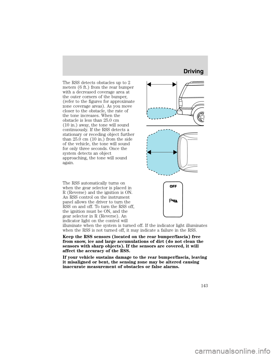
The RSS detects obstacles up to 2
meters (6 ft.) from the rear bumper
with a decreased coverage area at
the outer corners of the bumper,
(refer to the figures for approximate
zone coverage areas). As you move
closer to the obstacle, the rate of
the tone increases. When the
obstacle is less than 25.0 cm
(10 in.) away, the tone will sound
continuously. If the RSS detects a
stationary or receding object further
than 25.0 cm (10 in.) from the side
of the vehicle, the tone will sound
for only three seconds. Once the
system detects an object
approaching, the tone will sound
again.
The RSS automatically turns on
when the gear selector is placed in
R (Reverse) and the ignition is ON.
An RSS control on the instrument
panel allows the driver to turn the
RSS on and off. To turn the RSS off,
the ignition must be ON, and the
gear selector in R (Reverse). An
indicator light on the control will
illuminate when the system is turned off. If the indicator light illuminates
when the RSS is not turned off, it may indicate a failure in the RSS.
Keep the RSS sensors (located on the rear bumper/fascia) free
from snow, ice and large accumulations of dirt (do not clean the
sensors with sharp objects). If the sensors are covered, it will
affect the accuracy of the RSS.
If your vehicle sustains damage to the rear bumper/fascia, leaving
it misaligned or bent, the sensing zone may be altered causing
inaccurate measurement of obstacles or false alarms.
OFF
Driving
143
Page 146 of 240
TRAILER TOWING
Trailer towing with your vehicle requires the optional trailer tow
electrical package and may require the use of an additional medium duty
trailer tow option package.
Trailer towing puts additional loads on your vehicle’s engine,
transmission, axle, brakes, tires, and suspension. For your safety and to
maximize vehicle performance, be sure to use the proper equipment
while towing.
Follow these guidelines to ensure safe towing procedure:
•Stay within your vehicle’s load limits. If exceeded, cargo should be
removed from the trailer and/or the vehicle until all weights are within
specified limits.
•Thoroughly prepare your vehicle for towing. Refer toPreparing to
towin this chapter.
•Use extra caution when driving while trailer towing. Refer toDriving
while you towin this chapter.
•Service your vehicle more frequently if you tow a trailer. Refer to
Special Operating Conditions in the scheduled maintenance guide.
•Do not tow a trailer until your vehicle has been driven at least 800 km
(500 miles).
•Refer to the instructions included with towing accessories for the
proper installation and adjustment specifications.
If your vehicle is equipped with the optional heavy duty trailer tow
wiring, it is pre-wired for trailer towing. An electrical connector is
provided under the instrument panel for installing a customer-supplied
electric brake controller. Another electrical connector is provided at the
hitch. This connector provides power to the trailer for taillamps, stop
and turn lamps, back up lamps, battery charge, electric brakes (when a
customer provided controller is installed) and ground. The kit included
with your vehicle provides you with adaptors to attach the brake
controller and convert the hitch connector for Class I trailer usage.
Driving
146
Page 153 of 240
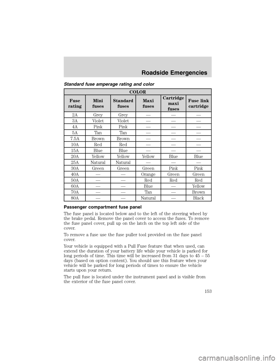
Standard fuse amperage rating and color
COLOR
Fuse
ratingMini
fusesStandard
fusesMaxi
fusesCartridge
maxi
fusesFuse link
cartridge
2A Grey Grey———
3A Violet Violet———
4A Pink Pink———
5A Tan Tan———
7.5A Brown Brown———
10A Red Red———
15A Blue Blue———
20A Yellow Yellow Yellow Blue Blue
25A Natural Natural———
30A Green Green Green Pink Pink
40A——Orange Green Green
50A——Red Red Red
60A——Blue—Yellow
70A——Ta n—Brown
80A——Natural—Black
Passenger compartment fuse panel
The fuse panel is located below and to the left of the steering wheel by
the brake pedal. Remove the panel cover to access the fuses. To remove
the fuse panel cover, pull up on the latch on the top left side of the
cover.
To remove a fuse use the fuse puller tool provided on the fuse panel
cover.
Your vehicle is equipped with a Pull Fuse feature that when used, can
extend the duration of your battery life while your vehicle is parked for
long periods of time. This time will be increased from 31 days to 45–55
days (based on option content). You should use this feature when your
vehicle will be parked for long periods of times to ensure the vehicle
starts upon your return.
The pull fuse is located under the instrument panel and is visible from
the exterior of the fuse panel cover.
Roadside Emergencies
153
Page 185 of 240
INSTRUMENT PANEL AND CLUSTER LENS
Clean the instrument panel with a damp cloth, then dry with a dry cloth.
•Avoid cleaners or polish that increase the gloss of the upper portion of
the instrument panel. The dull finish in this area helps protect the
driver from undesirable windshield reflection.
Do not use chemical solvents or strong detergents when cleaning
the steering wheel or instrument panel to avoid contamination of
the air bag system.
•Be certain to wash or wipe your hands clean if you have been in
contact with certain products such as insect repellent and suntan
lotion in order to avoid possible damage to the painted surfaces.
INTERIOR TRIM
•Clean the interior trim areas with a damp cloth, then dry by wiping
with a dry, soft, clean cloth.
•Do not use household or glass cleaners as these may damage the
finish.
INTERIOR
For fabric, carpets, cloth seats, safety belts and seats equipped with side
air bags:
•Remove dust and loose dirt with a vacuum cleaner.
•Remove light stains and soil with Ford Extra Strength Upholstery
Cleaner (E8AZ-19523–AA).
•If grease or tar is present on the material, spot-clean the area first
with Motorcraft Spot and Stain Remover (ZC-14).
•Never saturate the seat covers with cleaning solution.
•Do not use household cleaning products or glass cleaners, which can
stain and discolor the fabric and affect the flame retardant abilities of
the seat materials.
Do not use cleaning solvents, bleach or dye on the vehicle’s
safety belts, as these actions may weaken the belt webbing.
Cleaning
185
Page 189 of 240
OPENING THE HOOD
1. Inside the vehicle, pull the hood
release handle located under the
bottom left corner of the instrument
panel.
2. Go to the front of the vehicle and release the auxiliary latch that is
located under the front center of
the hood.
3. Lift the hood and secure it with
the prop rod. Your vehicle’s hood
has two locations for the prop rod
to be placed. These locations
provide two different hood opening
positions. Use the location which
best suits your needs.
HOOD
Maintenance and Specifications
189