Page 37 of 240
This control also has other features that are activated whenany door is
opened:
•Rotate to full up position or next position (adjustment dial) to turn on
all interior lights.
•Rotate to first lower detent position to activate“sleeping baby
mode”—dome lamps will remain off and only the lower lamps will
illuminate.
•The second lower detent position (full down) will shut off all interior
lights.
The dome lamp will not illuminate if the control switch is in the OFF
position.
AIMING THE HEADLAMPS
The headlamps on your vehicle are properly aimed at the assembly plant.
If your vehicle has been in an accident the alignment of your headlamps
should be checked by a qualified service technician.
You will need one E8 Torx socket to make the adjustments.
Vertical aim adjustment
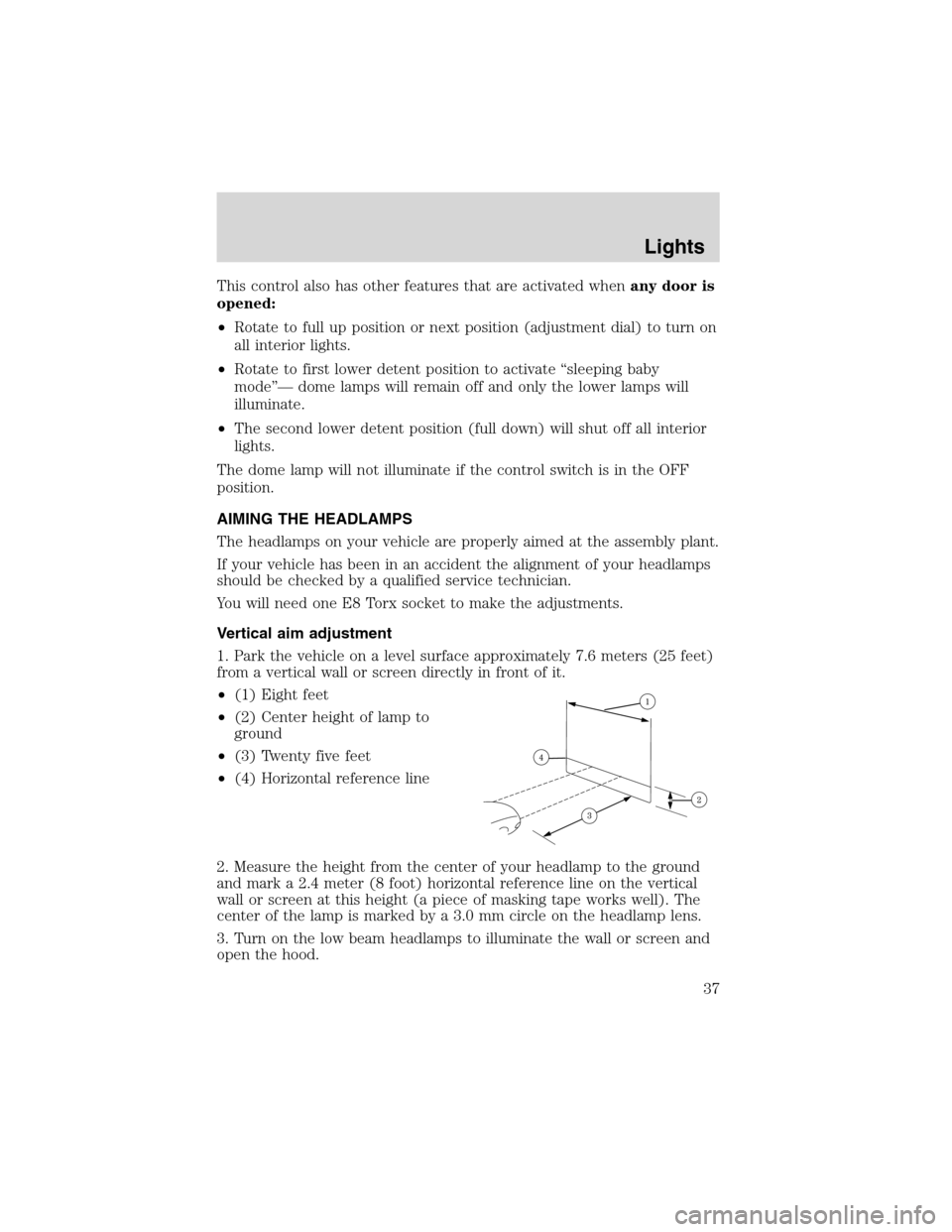
1. Park the vehicle on a level surface approximately 7.6 meters (25 feet)
from a vertical wall or screen directly in front of it.
•(1) Eight feet
•(2) Center height of lamp to
ground
•(3) Twenty five feet
•(4) Horizontal reference line
2. Measure the height from the center of your headlamp to the ground
and mark a 2.4 meter (8 foot) horizontal reference line on the vertical
wall or screen at this height (a piece of masking tape works well). The
center of the lamp is marked by a 3.0 mm circle on the headlamp lens.
3. Turn on the low beam headlamps to illuminate the wall or screen and
open the hood.
Lights
37
Page 38 of 240
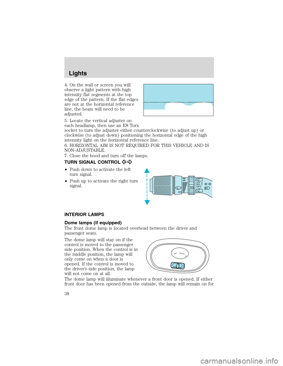
4. On the wall or screen you will
observe a light pattern with high
intensity flat segments at the top
edge of the pattern. If the flat edges
are not at the horizontal reference
line, the beam will need to be
adjusted.
5. Locate the vertical adjuster on
each headlamp, then use an E8 Torx
socket to turn the adjuster either counterclockwise (to adjust up) or
clockwise (to adjust down) positioning the horizontal edge of the high
intensity light on the horizontal reference line.
6. HORIZONTAL AIM IS NOT REQUIRED FOR THIS VEHICLE AND IS
NON-ADJUSTABLE.
7. Close the hood and turn off the lamps.
TURN SIGNAL CONTROL
•Push down to activate the left
turn signal.
•Push up to activate the right turn
signal.
INTERIOR LAMPS
Dome lamps (if equipped)
The front dome lamp is located overhead between the driver and
passenger seats.
The dome lamp will stay on if the
control is moved to the passenger
side position. When the control is in
the middle position, the lamp will
only come on when a door is
opened. If the control is moved to
the driver’s side position, the lamp
will not come on at all.
The dome lamp will illuminate whenever a front door is opened. If either
front door has been opened from the outside, the lamp will remain on for
Lights
38
Page 40 of 240
BULBS
Replacing exterior bulbs
Check the operation of all the bulbs frequently.
Using the right bulbs
Replacement bulbs are specified in the chart below. Headlamp bulbs
must be marked with an authorized“D.O.T.”for North America and an
“E”for Europe to assure lamp performance, light brightness and pattern
and safe visibility. The correct bulbs will not damage the lamp assembly
or void the lamp assembly warranty and will provide quality bulb burn
time.
Function Trade Number
Front park/turn lamps 3157 AK (amber)
Cornering lamps 3156K
Auxiliary parking lamps 912
Headlamps 9007
Rear license plate lamps 168
High-mount brake lamp 921
Rear turn lamps 3156K
Backup lamps 3156K
Brake/tail lamps 3157K
Dome lamp 921
Cargo liftgate lamp T-562
Map lamps/dome 578 (opt)
Stepwell lamp T-562
Front seat footwell 194
Front door mounted courtesy lamp 168
Second row reading lamp 578
All replacement bulbs are clear in color except where noted.
To replace all instrument panel lights - see your dealer.
Replacing headlamp bulbs
To remove the headlamp bulb:
1. Make sure headlamp switch is in the OFF position, then open the
hood.
Lights
40
Page 42 of 240
Replacing front parking/turn signal bulbs
1. Make sure the headlamp switch is
in the OFF position and open the
hood.
2. Pull the two headlamp retainer
pins up to release the headlamp
assembly, then pull the headlamp
assembly forward to expose the bulb
socket.
3. Remove bulb socket by turning it
counterclockwise, and pull the bulb
straight out of the socket.
Install the new bulb(s) in reverse order.
Replacing tail lamp/backup/turn lamp bulbs
1. Make sure the headlamp switch is
in the OFF position and open the
liftgate to expose the tail lamp
assembly, then remove the retaining
screws for the lamp assembly.
2. Carefully remove the lamp
assembly.
3. Rotate bulb socket
counterclockwise and remove from
lamp assembly.
4. Pull bulb straight out of socket and push in new bulb.
Install the new bulb(s) in reverse order.
Lights
42
Page 86 of 240
PERIMETER ALARM SYSTEM (IF EQUIPPED)
The perimeter anti-theft system will help prevent your vehicle from
unauthorized entry.
If there is any potential perimeter anti-theft problem with your vehicle,
ensureALL remote entry transmittersare taken to the dealership to
aid in troubleshooting.
Arming the system
When armed, this system will help protect your vehicle from
unauthorized entry. When unauthorized entry occurs, the system will
flash the turn signal lamps and side repeaters and honk the horn.
The system is ready to arm whenever the key is removed from the
ignition. Any of the following actions will prearm the alarm system:
•Press the remote entry lock control
•Press the interior power door lock control while the door is open
Twenty seconds after one of the above events occurs, any door/hood that
is closed is armed.
Any door/hood that is still open is prearmed and waiting for the
door/hood to be closed.
Once that input is closed, the input will arm in 20 seconds and the
exterior lamps may flash.
Disarming the system
You can disarm the system by any of the following actions:
•Press the transmitter unlock control.
•Unlock the doors with a key.
•Turn a programmed SecuriLock key to RUN /START.
Locks and Security
86
Page 189 of 240
OPENING THE HOOD
1. Inside the vehicle, pull the hood
release handle located under the
bottom left corner of the instrument
panel.
2. Go to the front of the vehicle and release the auxiliary latch that is
located under the front center of
the hood.
3. Lift the hood and secure it with
the prop rod. Your vehicle’s hood
has two locations for the prop rod
to be placed. These locations
provide two different hood opening
positions. Use the location which
best suits your needs.
HOOD
Maintenance and Specifications
189
Page 192 of 240
1. Make sure the vehicle is on level ground.
2. Turn the engine off and wait a few minutes for the oil to drain into the
oil pan.
3. Set the parking brake and ensure the gearshift is securely latched in P
(Park).
4. Open the hood. Protect yourself from engine heat.
5. Locate and carefully remove the
engine oil level indicator (dipstick).
6. Wipe the indicator clean. Insert the indicator fully, then remove it
again.
•If the oil level isbetween the MIN and MAX marks,the oil level is
acceptable.DO NOT ADD OIL.
•If the oil level is below the MIN
mark, add enough oil to raise the
level within the MIN-MAX range.
MAX MIN
Maintenance and Specifications
192
Page 229 of 240
Hood deflectors
Locking gas cap
Molded splash guards
Molded vinyl floor mats
Rear air deflector
Side window deflectors
Underbody security lighting
Universal floor mats
For maximum vehicle performance, keep the following information in
mind when adding accessories or equipment to your vehicle:
•When adding accessories, equipment, passengers and luggage to your
vehicle, do not exceed the total weight capacity of the vehicle or of
the front or rear axle (GVWR or GAWR as indicated on the Safety
compliance certification label). Consult your dealer for specific weight
information.
•The Federal Communications Commission (FCC) and Canadian Radio
Telecommunications Commission (CRTC) regulate the use of mobile
communications systems - such as two-way radios, telephones and
theft alarms - that are equipped with radio transmitters. Any such
equipment installed in your vehicle should comply with FCC or CRTC
regulations and should be installed only by a qualified service
technician.
•Mobile communications systems may harm the operation of your
vehicle, particularly if they are not properly designed for automotive
use or are not properly installed. When operated, such systems may
cause the engine to stumble or stall or cause the transmission to be
damaged or operate improperly. In addition, such systems may be
damaged or their performance may be affected by operating your
vehicle. (Citizens band [CB] transceivers, garage door openers and
other transmitters with outputs of five watts or less will not ordinarily
affect your vehicle’s operation.)
•Ford cannot assume responsibility for any adverse effects or damage
that may result from the use of such equipment.
Accessories
229