2003 FORD WINDSTAR air condition
[x] Cancel search: air conditionPage 1 of 240

Introduction 4
Instrument Cluster 10
Warning and control lights 10
Gauges 13
Entertainment Systems 16
AM/FM stereo cassette with CD 16
AM/FM stereo cassette 18
AM/FM stereo with CD 24
Rear seat controls 27
Climate Controls 30
Manual heating and air conditioning 30
Rear window defroster 34
Lights 35
Headlamps 35
Turn signal control 38
Bulb replacement 40
Driver Controls 44
Windshield wiper/washer control 44
Steering wheel adjustment 45
Power windows 50
Mirrors 51
Speed control (Cruise control) 53
Message center 62
Locks and Security 75
Keys 75
Locks 75
Anti-theft system 77
Table of Contents
1
Page 10 of 240
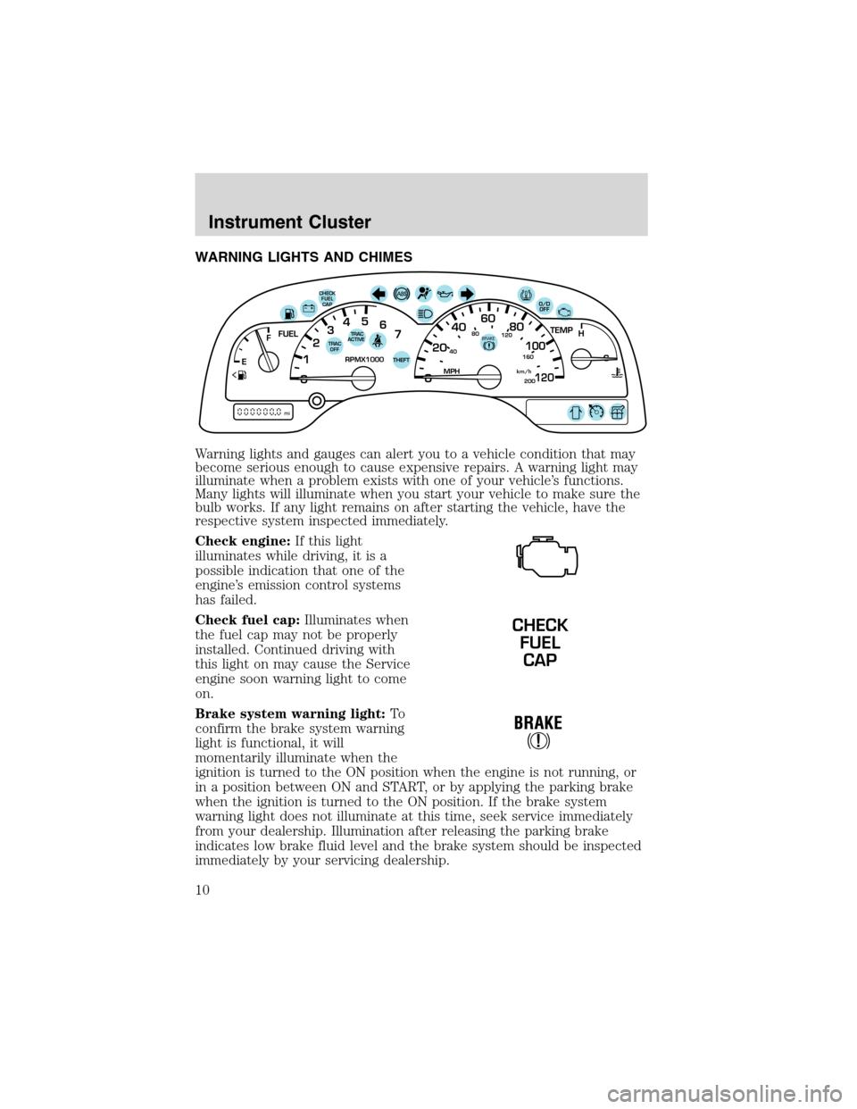
WARNING LIGHTS AND CHIMES
Warning lights and gauges can alert you to a vehicle condition that may
become serious enough to cause expensive repairs. A warning light may
illuminate when a problem exists with one of your vehicle’s functions.
Many lights will illuminate when you start your vehicle to make sure the
bulb works. If any light remains on after starting the vehicle, have the
respective system inspected immediately.
Check engine:If this light
illuminates while driving, it is a
possible indication that one of the
engine’s emission control systems
has failed.
Check fuel cap:Illuminates when
the fuel cap may not be properly
installed. Continued driving with
this light on may cause the Service
engine soon warning light to come
on.
Brake system warning light:To
confirm the brake system warning
light is functional, it will
momentarily illuminate when the
ignition is turned to the ON position when the engine is not running, or
in a position between ON and START, or by applying the parking brake
when the ignition is turned to the ON position. If the brake system
warning light does not illuminate at this time, seek service immediately
from your dealership. Illumination after releasing the parking brake
indicates low brake fluid level and the brake system should be inspected
immediately by your servicing dealership.
40
4080
120
160
20020
12345
6
760
80100
120MPH RPMX1000 THEFT
TRAC
ACTIVE TRAC
OFFTEMP
H
FFUEL
E
km/h
BRAKE
mi
O/D
OFFCHECK
FUEL
CAP
CHECK
FUEL
CAP
Instrument Cluster
10
Page 30 of 240
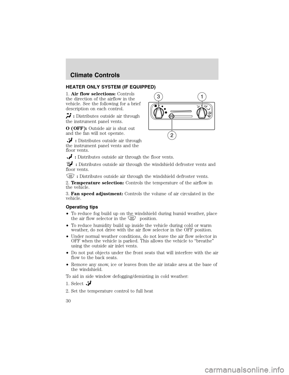
HEATER ONLY SYSTEM (IF EQUIPPED)
1.Air flow selections:Controls
the direction of the airflow in the
vehicle. See the following for a brief
description on each control.
:Distributes outside air through
the instrument panel vents.
O (OFF):Outside air is shut out
and the fan will not operate.
:Distributes outside air through
the instrument panel vents and the
floor vents.
:Distributes outside air through the floor vents.
:Distributes outside air through the windshield defroster vents and
floor vents.
:Distributes outside air through the windshield defroster vents.
2.Temperature selection:Controls the temperature of the airflow in
the vehicle.
3.Fan speed adjustment:Controls the volume of air circulated in the
vehicle.
Operating tips
•To reduce fog build up on the windshield during humid weather, place
the air flow selector in the
position.
•To reduce humidity build up inside the vehicle during cold or warm
weather, do not drive with the air flow selector in the OFF position.
•Under normal weather conditions, do not leave the air flow selector in
OFF when the vehicle is parked. This allows the vehicle to“breathe”
using the outside air inlet vents.
•Do not put objects under the front seats that will interfere with the air
flow to the back seats.
•Remove any snow, ice or leaves from the air intake area at the base of
the windshield.
To aid in side window defogging/demisting in cold weather:
1. Select
2. Set the temperature control to full heat
31
2
Climate Controls
30
Page 31 of 240
3. Set the fan speed to HI
4. Direct the outer instrument panel vents towards the side windows
To increase airflow to the outer instrument panel vents, close the vents
located in the middle of the instrument panel.
Do not place objects on top of the instrument panel as these
objects may become projectiles in a collision or sudden stop.
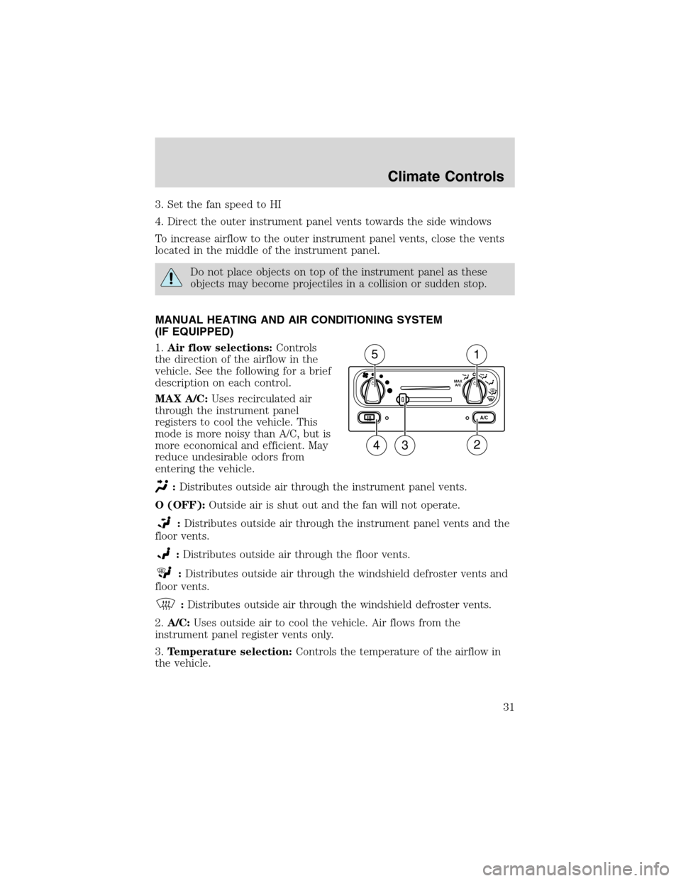
MANUAL HEATING AND AIR CONDITIONING SYSTEM
(IF EQUIPPED)
1.Air flow selections:Controls
the direction of the airflow in the
vehicle. See the following for a brief
description on each control.
MAX A/C:Uses recirculated air
through the instrument panel
registers to cool the vehicle. This
mode is more noisy than A/C, but is
more economical and efficient. May
reduce undesirable odors from
entering the vehicle.
:Distributes outside air through the instrument panel vents.
O (OFF):Outside air is shut out and the fan will not operate.
:Distributes outside air through the instrument panel vents and the
floor vents.
:Distributes outside air through the floor vents.
:Distributes outside air through the windshield defroster vents and
floor vents.
:Distributes outside air through the windshield defroster vents.
2.A/C:Uses outside air to cool the vehicle. Air flows from the
instrument panel register vents only.
3.Temperature selection:Controls the temperature of the airflow in
the vehicle.
A/C
MAX
A/C
15
234
Climate Controls
31
Page 32 of 240
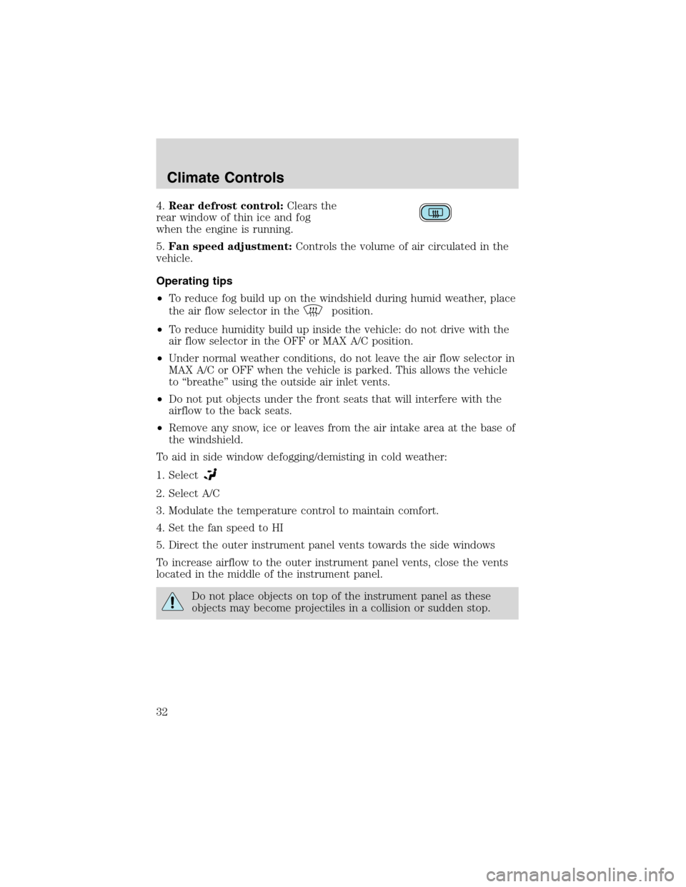
4.Rear defrost control:Clears the
rear window of thin ice and fog
when the engine is running.
5.Fan speed adjustment:Controls the volume of air circulated in the
vehicle.
Operating tips
•To reduce fog build up on the windshield during humid weather, place
the air flow selector in the
position.
•To reduce humidity build up inside the vehicle: do not drive with the
air flow selector in the OFF or MAX A/C position.
•Under normal weather conditions, do not leave the air flow selector in
MAX A/C or OFF when the vehicle is parked. This allows the vehicle
to“breathe”using the outside air inlet vents.
•Do not put objects under the front seats that will interfere with the
airflow to the back seats.
•Remove any snow, ice or leaves from the air intake area at the base of
the windshield.
To aid in side window defogging/demisting in cold weather:
1. Select
2. Select A/C
3. Modulate the temperature control to maintain comfort.
4. Set the fan speed to HI
5. Direct the outer instrument panel vents towards the side windows
To increase airflow to the outer instrument panel vents, close the vents
located in the middle of the instrument panel.
Do not place objects on top of the instrument panel as these
objects may become projectiles in a collision or sudden stop.
Climate Controls
32
Page 33 of 240
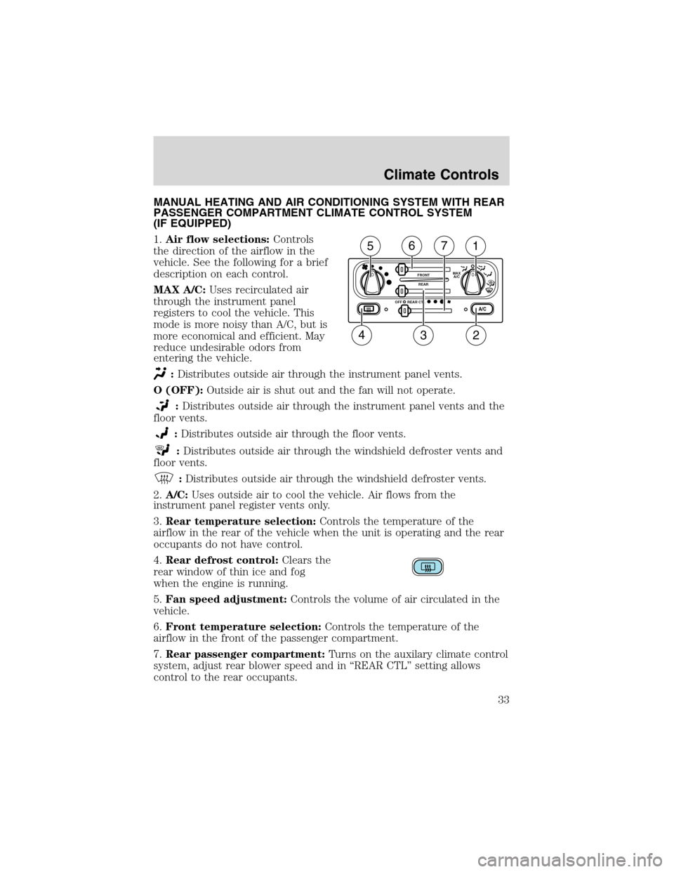
MANUAL HEATING AND AIR CONDITIONING SYSTEM WITH REAR
PASSENGER COMPARTMENT CLIMATE CONTROL SYSTEM
(IF EQUIPPED)
1.Air flow selections:Controls
the direction of the airflow in the
vehicle. See the following for a brief
description on each control.
MAX A/C:Uses recirculated air
through the instrument panel
registers to cool the vehicle. This
mode is more noisy than A/C, but is
more economical and efficient. May
reduce undesirable odors from
entering the vehicle.
:Distributes outside air through the instrument panel vents.
O (OFF):Outside air is shut out and the fan will not operate.
:Distributes outside air through the instrument panel vents and the
floor vents.
:Distributes outside air through the floor vents.
:Distributes outside air through the windshield defroster vents and
floor vents.
:Distributes outside air through the windshield defroster vents.
2.A/C:Uses outside air to cool the vehicle. Air flows from the
instrument panel register vents only.
3.Rear temperature selection:Controls the temperature of the
airflow in the rear of the vehicle when the unit is operating and the rear
occupants do not have control.
4.Rear defrost control:Clears the
rear window of thin ice and fog
when the engine is running.
5.Fan speed adjustment:Controls the volume of air circulated in the
vehicle.
6.Front temperature selection:Controls the temperature of the
airflow in the front of the passenger compartment.
7.Rear passenger compartment:Turns on the auxilary climate control
system, adjust rear blower speed and in“REAR CTL”setting allows
control to the rear occupants.
A/C
FRONT
REAR
OFFMAX
A/C
REAR CTL
234
1567
Climate Controls
33
Page 70 of 240
Compass display (if equipped)
The compass reading may be affected when you drive near large
buildings, bridges, power lines and powerful broadcast antennas.
Magnetic or metallic objects placed in, on or near the vehicle may also
affect compass accuracy.
Usually, when something affects the compass readings, the compass will
correct itself after a few days of operating your vehicle in normal
conditions. If the compass still appears to be inaccurate, a manual
calibration may be necessary. Refer toCompass zone/calibration
adjustment.
Most geographic areas (zones) have a magnetic north compass point that
varies slightly from the northerly direction on maps. This variation is four
degrees between adjacent zones and will become noticeable as the
vehicle crosses multiple zones. A correct zone setting will eliminate this
error. Refer toCompass zone/calibration adjustment.
Compass zone/calibration adjustment
Perform this adjustment in an open area free from steel structures and
high voltage lines.
For optimum calibration, turn off all electrical accessories (heater/air
conditioning, wipers, etc.) and make sure all vehicle doors are shut.
1. Turn ignition to the ON position.
2. Start the engine.
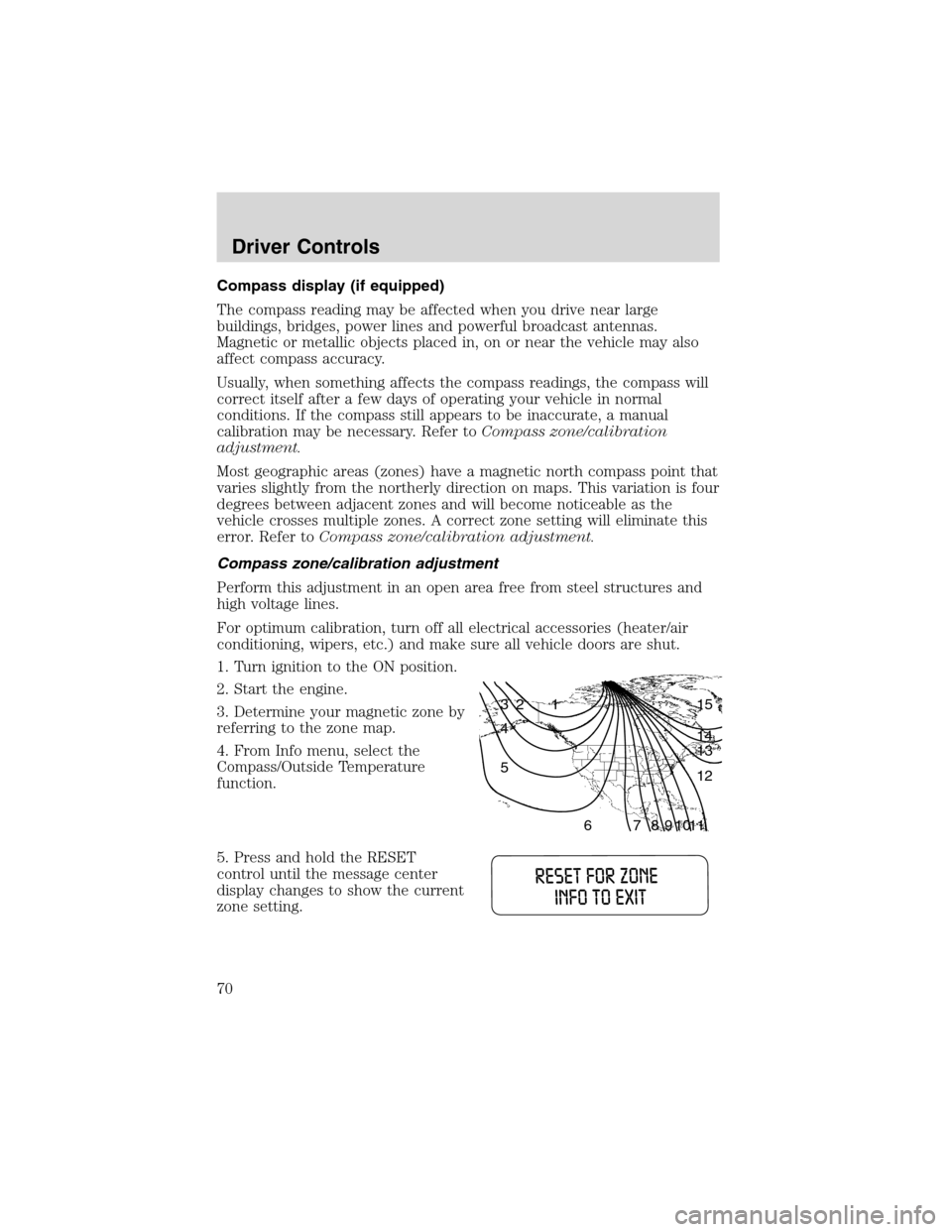
3. Determine your magnetic zone by
referring to the zone map.
4. From Info menu, select the
Compass/Outside Temperature
function.
5. Press and hold the RESET
control until the message center
display changes to show the current
zone setting.
1 2 3
4
5
6 7 8 9 101112 13 14 15
Driver Controls
70
Page 98 of 240
Always latch the vehicle seat to the floor, whether the seat is
occupied or empty. If not latched, the seat may cause injury
during a sudden stop.
SAFETY RESTRAINTS
Personal Safety System
The Personal Safety System provides an improved overall level of frontal
crash protection to front seat occupants and is designed to help further
reduce the risk of air bag-related injuries. The system is able to analyze
different occupant conditions and crash severity before activating the
appropriate safety devices to help better protect a range of occupants in
a variety of frontal crash situations.
Your vehicle’s Personal Safety System consists of:
•Driver and passenger dual-stage air bag supplemental restraints.
•Front safety belts with pretensioners, energy management retractors,
and safety belt usage sensors.
•Driver’s seat position sensor.
•Passenger occupant classification sensor
•Front crash severity sensor.
•Restraints Control Module (RCM) with impact and safing sensors.
•Restraint system warning light and back-up tone.
•The electrical wiring for the air bags, crash sensor(s), safety belt
pretensioners, front safety belt usage sensors, driver seat position
sensor, passenger occupant classification sensor, and indicator lights.
How does the personal safety system work?
The Personal safety system can adapt the deployment strategy of your
vehicle’s safety devices according to crash severity and occupant
conditions. A collection of crash and occupant sensors provides
information to the Restraints control module (RCM). During a crash, the
RCM activates the safety belt pretensioners and/or either one or both
stages of the dual-stage air bag supplemental restraints based on crash
severity and occupant conditions.
The fact that the pretensioners or air bags did not activate for both front
seat occupants in a collision does not mean that something is wrong with
the system. Rather, it means the Personal safety system determined the
Seating and Safety Restraints
98