Page 3260 of 4378
Instrument Cluster—
Base 4.6L Engine transmission)
16 — LOW FUEL level indicator
17 — SERVICE ENGINE SOON indicator
18 — THEFT indicator
19 — AIR BAG warning indicator
20 — Charging system indicator
21 — Safety belt warning indicator
Item Part
Number Description
1 — Fuel gauge
2 — Engine coolant temperature gauge
3 — Speedometer
4 — Turn signal/hazard indicator
5 — High beam indicator
6 — Tachometer
7 — Odometer
8 — Trip odometer reset button
9 — Voltmeter gauge
10 — Oil pressure gauge
11 — CHECK FUEL CAP indicator
12 — BRAKE warning indicator
13 — ABS warning indicator �K�l�j . 2 �b�a
42003 Mustang Workshop Manual
18. 11. 2011file:///C:/Ford/2000 - 2004/tsocache/SHEF_5108/S3B~us~en~ ...
Page 3261 of 4378
Instrument Cluster—
Cobra 14 — Traction control indicator
15 — Overdrive off (O/D OFF) indicator (automatic
transmission)
16 — LOW FUEL level indicator
17 — SERVICE ENGINE SOON indicator
18 — THEFT indicator
19 — AIR BAG warning indicator
20 — Charging system indicator
21 — Safety belt warning indicator
Item Part
Number Description
1 — Fuel gauge
2 — Engine coolant temperature gauge
3 — Speedometer
4 — Turn signal/hazard indicator
5 — High beam indicator
6 — Tachometer
7 — Odometer
8 — Trip odometer reset button
9 — Boost gauge
10 — Oil pressure gauge
11 — CHECK FUEL CAP indicator
12 — BRAKE warning indicator �K�l�j . 3 �b�a
42003 Mustang Workshop Manual
18. 11. 2011file:///C:/Ford/2000 - 2004/tsocache/SHEF_5108/S3B~us~en~ ...
Page 3262 of 4378
13 — ABS warning indicator
14 — Traction control indicator
15 — Overdrive off (O/D OFF) indicator (automatic
transmission)
16 — LOW FUEL level indicator
17 — SERVICE ENGINE SOON indicator
18 — THEFT indicator
19 — AIR BAG warning indicator
20 — Charging system indicator
21 — Safety belt warning indicator �K�l�j . 4 �b�a
42003 Mustang Workshop Manual
18. 11. 2011file:///C:/Ford/2000 - 2004/tsocache/SHEF_5108/S3B~us~en~ ...
Page 3339 of 4378

GENERAL PROCEDURES
Belt Minder Deactivating/Activating
Preparation
1. Before deactivating/activating the belt minder, set the parking brake.
2. Place the gearshift in P (Park) (automatic transmission) or the neutral position (manual transmission).
3. Place the ignition switch in the OFF position.
4. Close all the vehicle doors.
5. Unbuckle the driver safety belt.
6. Place the parklamps/headlamps switch in the OFF position. (If the vehicle is equipped with Autolamps, this will not affect the procedure.)
Deactivating/Activating 1. Turn the ignition switch to the RUN position. (Do not start the engine.)
2. Wait until the safety belt warning lamp turns off. (approximately one to two minutes)
3. NOTE: Steps 3 through 5 must be completed within 60 seconds or the procedure must be
repeated.
Buckle then unbuckle the safety belt three times, ending with the safety belt unbuckled. This
portion of the procedure can be done before or during belt minder warning activation.
4. Turn the parklamps/headlamps on then off.
5. Buckle then unbuckle the safety belt three times ending with the safety belt unbuckled. After this step the safety belt warning lamp will be illuminated for three seconds.
6. Within seven seconds of the safety belt warning lamp turning off, buckle then unbuckle the safety belt. This will enable the belt minder if disabled or disable the belt minder if enabled.
7. The following sequence of events confirm the belt minder is enabled: �zflashing of the safety belt warning belt lamp four times per second for three seconds
�z three seconds with the safety belt lamp off
�z flashing the safety belt lamp four times per second for three seconds again
8. The safety belt lamp flashing four times per second for three seconds provides confirmation that the belt minder is disabled. 9. After confirmation, the deactivation/activation procedure is complete. SECTION 413-
09: Warning Devices 2003 Mustang Workshop Manual �K�l�j . 1 �b�a
22003 Mustang Workshop Manual
18. 11. 2011file:///C:/Ford/2000 - 2004/tsocache/SHEF_5108/S3B~us~en~ ...
Page 3359 of 4378

8. If the draw is found to be excessive, pull fuses from the battery/central junction box one at a
time and note the current drop. Do not reinstall the fuses until you are finished testing.
9. Check the wiring schematic in the wiring diagram for any circuits that run from the battery without passing through the battery/central junction box. Disconnect these circuits if the draw is
still excessive.
Battery— Electronic Drains Which Shut Off When the Battery Cable is Disconnected
1. Repeat the steps of the battery drain testing.
2. Make sure all doors are closed and accessories are off. Without starting the engine, turn the ignition switch to RUN for a moment and then OFF. Wait a few minutes for the illuminated entry
lamps to turn off if equipped.
3. Connect the ammeter and read the amperage draw.
The current reading (current drain) should be less than 50 mA (0.05 amp). If the current drain exceeds
50 mA (0.05 amp) after a few minutes, and if this drain did not show in previous tests, the drain is most
likely caused by an inoperative electronic component. As in previous tests, remove the fuses from the
battery/central junction box one at a time to locate the problem circuit.
Generator On- Vehicle Tests
CAUTION: To prevent damage to the generator, do not make jumper wire connections
except as directed.
CAUTION: Do not allow any metal object to come in contact with the housing and the
internal diode cooling fins with key on or off. A short circuit will result and burn out the diodes.
NOTE: Battery posts and cable clamps must be clean and tight for accurate meter indications.
NOTE: Refer to the Battery Tester Procedure Manual for complete directions for testing the charging
system.
1. Turn off all lamps and electrical components.
2. Place the vehicle in transmission range NEUTRAL and apply the parking brake.
3. Carry out the Load Test and No- Load Test according to the following component tests:
Generator On- Vehicle Tests— Load Test
1. Switch the battery tester to the ammeter function.
2. Connect the positive and negative leads of the battery tester to the corresponding battery terminals.
3. Connect the current probe to the generator B+ output terminal, circuit 38 (BK/OG). �K�l�j . 12 �b�a
142003 Mustang Workshop Manual
18. 11. 2011file:///C:/Ford/2000 - 2004/tsocache/SHEF_5108/S3B~us~en~ ...
Page 3444 of 4378
DESCRIPTION AND OPERATION
Exterior Lighting
The exterior lighting system consists of the following components:
�zheadlamps (13008)
�z parking lamps
�z rear lamps (13404)
�z high mounted stoplamp
�z license lamps
�z front turn lamps
�z reversing lamps
�z fog lamps (if equipped)
�z headlamp switch (11654)
�z fog lamp switch (if equipped)
�z brake pedal position (BPP) switch (13480)
�z multifunction switch (13K359)
�z digital transmission range (DTR) sensor (A/T)
�z reversing lamp switch (M/T)
�z electronic flasher
�z fog lamp relays (if equipped)
SECTION 417-
01: Exterior Lighting 2003 Mustang Workshop Manual �K�l�j . 1 �b�a
12003 Mustang Workshop Manual
18. 11. 2011file:///C:/Ford/2000 - 2004/tsocache/SHEF_5108/S3B~us~en~ ...
Page 3471 of 4378

DIAGNOSIS AND TESTING
Reversing Lamps
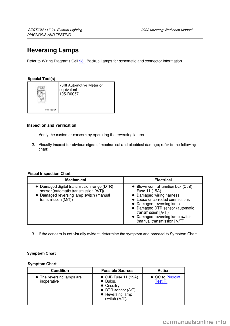
Refer to Wiring Diagrams Cell
93 , Backup Lamps for schematic and connector information.
Inspection and Verification 1. Verify the customer concern by operating the reversing lamps.
2. Visually inspect for obvious signs of mechanical and electrical damage; refer to the following chart:
3. If the concern is not visually evident, determine the symptom and proceed to Symptom Chart.
Symptom Chart SECTION 417-
01: Exterior Lighting 2003 Mustang Workshop Manual Special Tool(s)
73III Automotive Meter or
equivalent
105-
R0057
Visual Inspection Chart Mechanical Electrical
�z
Damaged digital transmission range (DTR)
sensor (automatic transmission [A/T])
�z Damaged reversing lamp switch (manual
transmission [M/T]) �z
Blown central junction box (CJB)
Fuse 11 (15A)
�z Damaged wiring harness
�z Loose or corroded connections
�z Damaged reversing lamp
�z Damaged DTR sensor (automatic
transmission [A/T])
�z Damaged reversing lamp switch
(manual transmission [M/T])
Symptom Chart Condition
Possible Sources Action
�z The reversing lamps are
inoperative �z
CJB Fuse 11 (15A).
�z Bulbs.
�z Circuitry.
�z DTR sensor (A/T).
�z Reversing lamp
switch (M/T). �z
GO to Pinpoint Test R . �K�l�j . 1 �b�a
42003 Mustang Workshop Manual
18. 11. 2011file:///C:/Ford/2000 - 2004/tsocache/SHEF_5108/S3B~us~en~ ...
Page 3492 of 4378
DESCRIPTION AND OPERATION
Interior Lighting
The interior lighting system consists of the following:
�zmap/dome lamp assembly
�z rear- high mount/cargo lamp assembly
�z dimmer switch
�z door ajar switch (located on the door latches)
�z rear view mirror interior lamp (convertible only)
�z courtesy lamp
�z vanity mirror lamp assembly
�z transmission range indicator
SECTION 417-
02: Interior Lighting 2003 Mustang Workshop Manual �K�l�j . 1 �b�a
12003 Mustang Workshop Manual
18. 11. 2011file:///C:/Ford/2000 - 2004/tsocache/SHEF_5108/S3B~us~en~ ...