Page 1554 of 4378
7.
NOTE: The oil groove on the thrust washer must face toward the front of the engine (against the
crankshaft thrust surface).
Install the thrust washer to the rear of the No. 5 upper main bearing.
8. NOTE: Rotate the jack screws into the bearing caps enough to provide clearance to the cylinder
block, prior to installing the bearing caps
NOTE: Install the thrust bearing to the rear main bearing cap and lubricate it with clean engine
oil.
NOTE: Install the crankshaft lower main bearings into the main bearing caps and lubricate them
with clean engine oil.
Apply forward force to the crankshaft, so that the crankshaft thrust face is against the No. 5
bulkhead. With the crankshaft in this position, locate the No. 5 main bearing cap on the cylinder
block and tap into place using a plastic or dead blow hammer.
�zInstall the four remaining main bearing caps. �K�l�j . 5 �b�a
352003 Mustang Workshop Manual
17. 11. 2011file:///C:/Ford/2000 - 2004/tsocache/SHEF_4464/S3B~us~en~ ...
Page 1789 of 4378
4. Clean and inspect the piston and connecting rod. For additional information, refer to
Section 303 - 00 .
Assembly 1. NOTE: Connecting rod must be installed into piston with identification markings toward front.
Position the connecting rod in the piston.
2. Lubricate the piston pin and pin bore with clean engine oil.
3. Install the piston pin in the piston and connecting rod assembly. �K�l�j . 2 �b�a
32003 Mustang Workshop Manual
17. 11. 2011file:///C:/Ford/2000 - 2004/tsocache/SHEF_4464/S3B~us~en~ ...
Page 2371 of 4378

A no-
drive condition can exist even with correct transmission fluid pressure because of inoperative
clutches or bands. An erratic shift can be located through a series of checks by substituting air
pressure for fluid pressure to determine the location of the malfunction.
Follow the procedure to determine the location of the inoperative clutch or band by introducing air
pressure into the various test plate passages.
NOTE: Use only dry, regulated 276 kPa (40 psi) maximum air pressure.
Apply air to the appropriate passage(s). A dull thud should be felt or heard or movement could be
observed when the clutch component applies. There should be no hissing sound when the component
is applied.
Cover the vent hole in the test plate with a clean, lint- free shop towel to prevent spray when the air is
applied. Plugging the vent hole during testing will result in inaccurate results.
1. Drain transmission fluid and remove the transmission fluid pan.
2. Remove the main control valve body.
3. Install transmission test plate and gasket. Tighten bolts to 10 Nm (89 lb- in).
4. NOTE: Do not apply air to the test plate vent hole.
Apply air to the appropriate clutch port (refer to the Transmission Air Test Plate illustration). A
dull thud may be heard or movement felt when the component is applied or released. If clutch
seals or check balls are leaking a hissing sound may be heard.
If the servos do not operate, disassemble, clean and inspect them to locate the source of the concern.
If air pressure applied to the clutch passages fails to operate a clutch, or operates clutches
simultaneously, inspect the fluid passages in the case.
If air pressure applied to the accumulator fails to operate an accumulator, remove and inspect case
passages and piston.
Clutch Pressure Test
The Clutch Pressure Test will diagnose a low- pressure condition or leakage in a clutch circuit. A
difference of 103 kPa (15 psi) or more between the clutch pressure and line pressure will prevent a
normal shift.
1. CAUTION: Pressure gauges affect the shift quality of the transmission. Care must
be taken not to accelerate or decelerate rapidly. Possible transmission failure can result.
Attach 0- 2068 kPa (0- 300 psi) pressure gauges to the line pressure tap and the appropriate
clutch pressure tap according to Band and Clutch Application Chart A&B. Gauges must be
accurate enough to distinguish a 103 kPa (15 psi) difference. (If this test is done in conjunction
with a control pressure test, pressure gauges will be attached to all pressure taps.) Have
sufficient flexible hose available to read the gauges in the vehicle.
2. Drive the vehicle. When pressure is applied to the clutch, note the difference between the line pressure gauge and the corresponding clutch pressure gauge.
3. If the difference in pressures is less than 103 kPa (15 psi), the corresponding clutch circuit does not have a pressure loss. The gauges on the line pressure tap and appropriate clutch pressure
tap can be switched to confirm that gauge calibration differences are not the cause. �K�l�j . 6 �b�a
72003 Mustang Workshop Manual
18. 11. 2011file:///C:/Ford/2000 - 2004/tsocache/SHEF_2748/S3B~us~en~ ...
Page 2480 of 4378
26. Using the special tools, remove the extension housing seal.
27.
NOTE: These bolts have been coated with a sealant. High break torque may be required to
remove these bolts.
Remove the extension housing.
1. Remove the four bolts and two nuts.
2. Remove the extension housing and the extension housing gasket.
28. Remove the parking pawl. 1. Remove the parking pawl shaft.
2. Remove the parking pawl return spring.
3. Remove the parking pawl.
29. Rotate the transmission to the vertical position with the output shaft towards the floor.
30. CAUTION: Extreme care must be taken during transmission connector removal. Do
not use a hammer on the connector body.
Place a screwdriver on the flat portion of the connector and push the connector out through the
bottom of the case. �K�l�j . 10 �b�a
162003 Mustang Workshop Manual
18. 11. 2011file:///C:/Ford/2000 - 2004/tsocache/SHEF_2748/S3B~us~en~ ...
Page 2499 of 4378
4. Using the special tool, install the intermediate clutch piston.
1. Position the intermediate clutch piston and the special tool onto the pump body.
2. Push the intermediate clutch piston to the bottom of the pump body bore, exerting even pressure and remove the special tool.
5. CAUTION: The piston bleed hole must be located at 12 o'clock position (towards
the top of the transmission). Shift problems may occur if installed incorrectly.
NOTE: The piston bleed hole is the only round hole in the pump body.
Locate the piston bleed hole.
6. Install by snapping the spring retainer assembly on pump body. �K�l�j . 5 �b�a
72003 Mustang Workshop Manual
18. 11. 2011file:///C:/Ford/2000 - 2004/tsocache/SHEF_2748/S3B~us~en~ ...
Page 2532 of 4378
2. Install the clutch piston outer seal so that when the piston is installed the sealing lip points
toward the bottom of the cylinder.
3. NOTE: Coat the inner and outer direct clutch piston seals, clutch cylinder sealing area and
piston inner sealing area with petroleum jelly.
Using the special tool, install the direct clutch piston.
4. Install the piston return spring and retainer assembly.
5. Using the special tool, compress the piston return spring and install the retaining ring.
6. NOTE: Before assembly, soak new clutch discs in clean automatic transmission fluid for 15
minutes.
Install the clutch pack retaining ring. 1. Alternate external spline (steel) plates and internal spline (friction) plates, starting with a steel plate and ending with the friction plate.
2. Install the clutch pack retaining ring. �K�l�j . 7 �b�a
112003 Mustang Workshop Manual
18. 11. 2011file:///C:/Ford/2000 - 2004/tsocache/SHEF_2748/S3B~us~en~ ...
Page 2587 of 4378

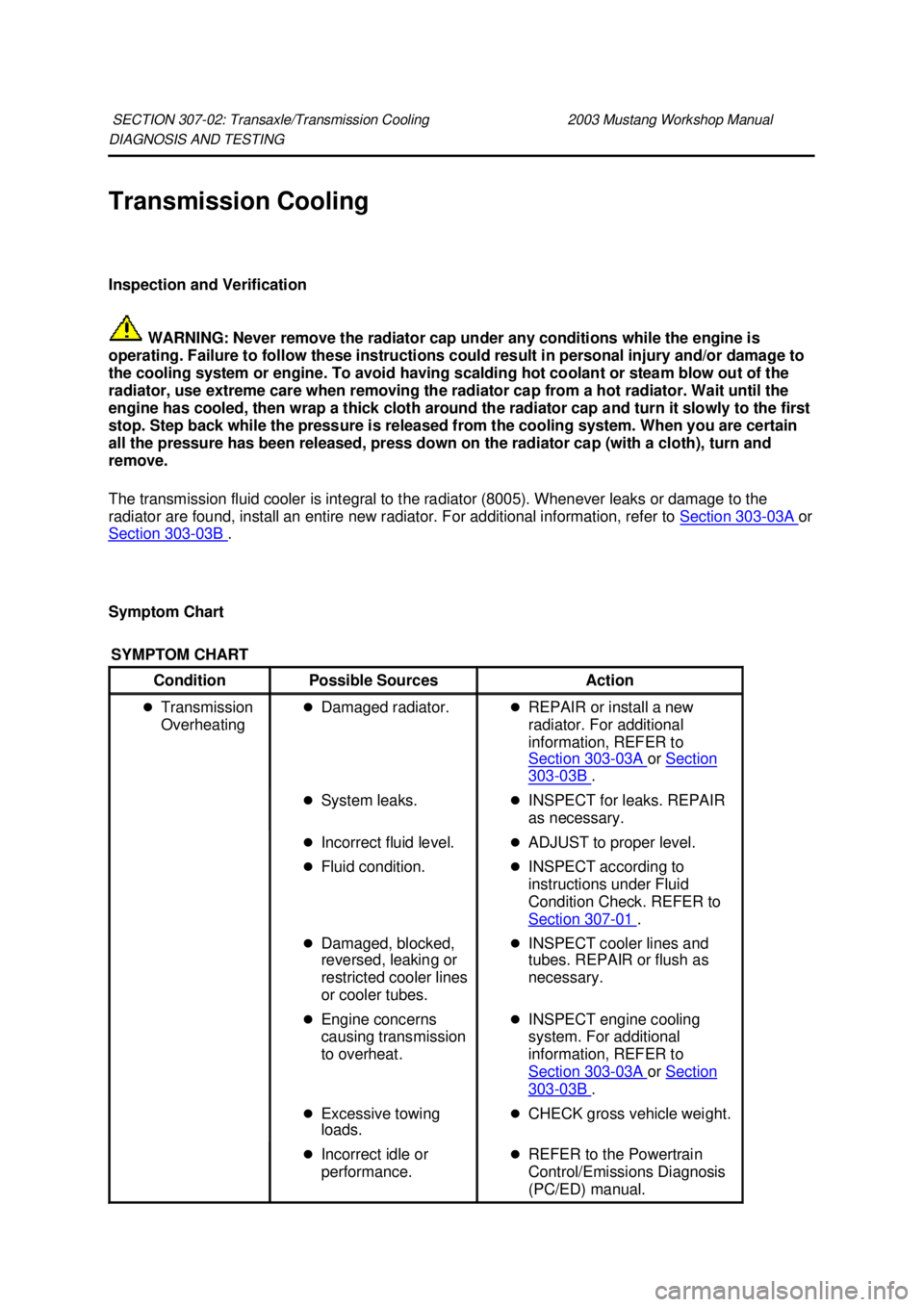
DIAGNOSIS AND TESTING
Transmission Cooling
Inspection and Verification
WARNING: Never remove the radiator cap under any conditions while the engine is
operating. Failure to follow these instructions could result in personal injury and/or damage to
the cooling system or engine. To avoid having scalding hot coolant or steam blow out of the
radiator, use extreme care when removing the radiator cap from a hot radiator. Wait until the
engine has cooled, then wrap a thick cloth around the radiator cap and turn it slowly to the first
stop. Step back while the pressure is released from the cooling system. When you are certain
all the pressure has been released, press down on the radiator cap (with a cloth), turn and
remove.
The transmission fluid cooler is integral to the radiator (8005). Whenever leaks or damage to the
radiator are found, install an entire new radiator. For additional information, refer to Section 303 - 03A or
Section 303 - 03B .
Symptom Chart SECTION 307-
02: Transaxle/Transmission Cooling 2003 Mustang Workshop Manual SYMPTOM CHART
Condition
Possible Sources Action
�z Transmission
Overheating �z
Damaged radiator. �zREPAIR or install a new
radiator. For additional
information, REFER to
Section 303 - 03A or
Section 303 - 03B .
�z System leaks. �zINSPECT for leaks. REPAIR
as necessary.
�z Incorrect fluid level. �zADJUST to proper level.
�z Fluid condition. �zINSPECT according to
instructions under Fluid
Condition Check. REFER to
Section 307 - 01 .
�z Damaged, blocked,
reversed, leaking or
restricted cooler lines
or cooler tubes. �z
INSPECT cooler lines and
tubes. REPAIR or flush as
necessary.
�z Engine concerns
causing transmission
to overheat. �z
INSPECT engine cooling
system. For additional
information, REFER to
Section 303 - 03A or
Section 303 - 03B .
�z Excessive towing
loads. �z
CHECK gross vehicle weight.
�z Incorrect idle or
performance. �z
REFER to the Powertrain
Control/Emissions Diagnosis
(PC/ED) manual. �K�l�j . 1 �b�a
22003 Mustang Workshop Manual
18. 11. 2011file:///C:/Ford/2000 - 2004/tsocache/SHEF_2748/S3B~us~en~ ...
Page 2629 of 4378

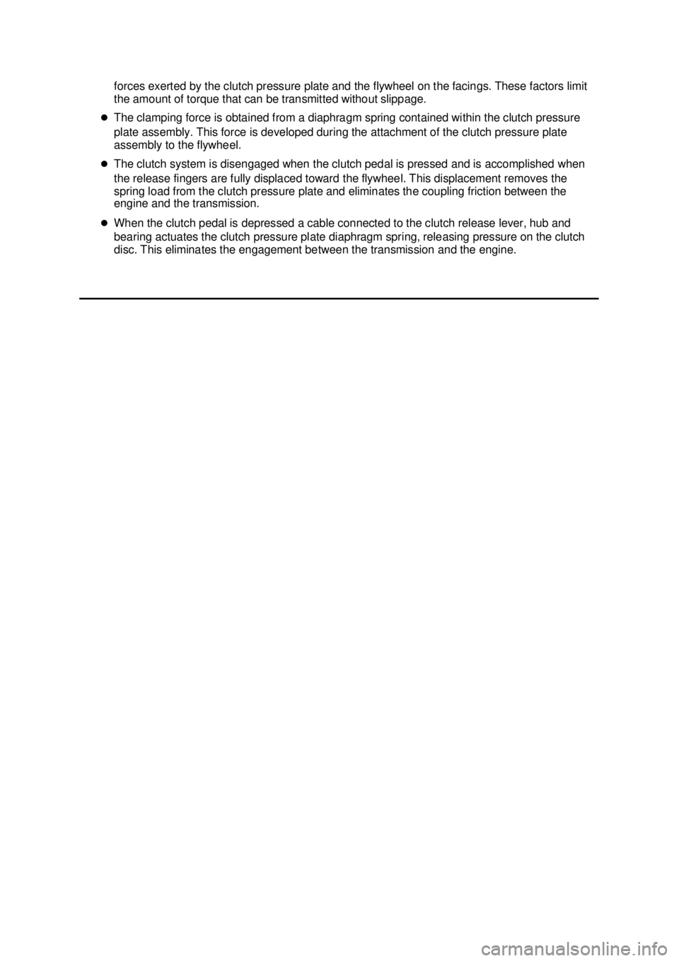
forces exerted by the clutch pressure plate and the flywheel on the facings. These factors limit
the amount of torque that can be transmitted without slippage.
�z The clamping force is obtained from a diaphragm spring contained within the clutch pressure
plate assembly. This force is developed during the attachment of the clutch pressure plate
assembly to the flywheel.
�z The clutch system is disengaged when the clutch pedal is pressed and is accomplished when
the release fingers are fully displaced toward the flywheel. This displacement removes the
spring load from the clutch pressure plate and eliminates the coupling friction between the
engine and the transmission.
�z When the clutch pedal is depressed a cable connected to the clutch release lever, hub and
bearing actuates the clutch pressure plate diaphragm spring, releasing pressure on the clutch
disc. This eliminates the engagement between the transmission and the engine. �K�l�j . 4 �b�a
42003 Mustang Workshop Manual
18. 11. 2011file:///C:/Ford/2000 - 2004/tsocache/SHEF_2308/S3B~us~en~ ...