Page 981 of 4378

16.
CAUTION: The cap screw is hidden; make sure to remove it or the engine front
cover will be damaged.
NOTE: Record the location, type and size of the fasteners.
Remove the engine front cover. �zSlide the engine front cover off the two dowels.
�z Remove and discard the engine front cover gasket.
Installation 1. CAUTION: In order to prevent foreign material from contaminating the engine block
or the engine front cover it is necessary to seal the coolant and oil passages of both
components. Failure to follow these directions will result in engine damage.
CAUTION: Do not use a surface conditioning pad or any other type of fibrous
abrasive disc to clean the gasket surfaces. Failure to follow these directions will result in
engine damage.
Clean and inspect the engine block and front cover as follows:
�zPack the exposed portion of the oil pan with clean shop towels.
�z Plug the oil and coolant passages.
�z Clean the gasket surfaces.
�z Clean all surfaces requiring gasket sealant with metal surface cleaner.
�z Using compressed air, remove any remaining foreign material from the engine block and
engine front cover.
�z Remove the shop towels from the oil pan.
�z Remove the plugs or seals from the engine block and engine front cover. �K�l�j . 4 �b�a
92003 Mustang Workshop Manual
17. 11. 2011file:///C:/Ford/2000 - 2004/tsocache/SHEF_4464/S3B~us~en~ ...
Page 1098 of 4378
CAUTION: Do not damage the cylinder wall with the sharp edges of the connecting
rod.
Install the piston with the arrow on the piston face pointing toward the front of the engine.
16. CAUTION: Inspect the connecting rod bearing clearance. For additional information,
refer to Section 303 - 00 .
CAUTION: The connecting rod cap will fit only one way.
Position the connecting lower rod bearing and the connecting rod cap on the connecting rod
and the crankshaft journal.
17. Install the rod caps. Tighten the bolts in three stages: �zStage 1: Tighten to 25 Nm (18 lb- ft).
�z Stage 2: Tighten to 45 Nm (33 lb- ft).
�z Stage 3: Tighten an additional 105 degrees. 18. Install the remaining pistons and the connecting rods. �K�l�j . 7 �b�a
282003 Mustang Workshop Manual
17. 11. 2011file:///C:/Ford/2000 - 2004/tsocache/SHEF_4464/S3B~us~en~ ...
Page 1258 of 4378

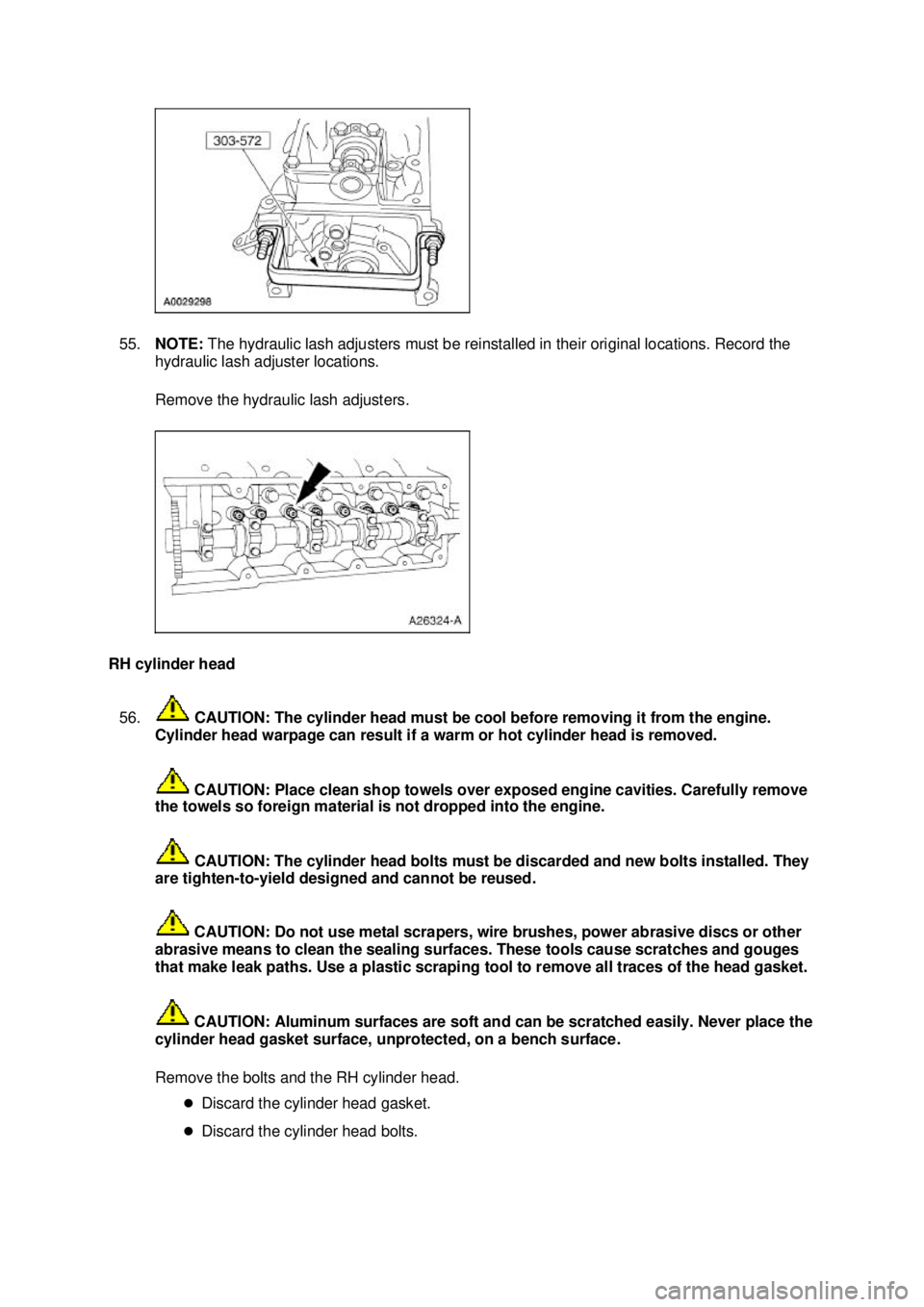
55.
NOTE: The hydraulic lash adjusters must be reinstalled in their original locations. Record the
hydraulic lash adjuster locations.
Remove the hydraulic lash adjusters.
RH cylinder head 56. CAUTION: The cylinder head must be cool before removing it from the engine.
Cylinder head warpage can result if a warm or hot cylinder head is removed.
CAUTION: Place clean shop towels over exposed engine cavities. Carefully remove
the towels so foreign material is not dropped into the engine.
CAUTION: The cylinder head bolts must be discarded and new bolts installed. They
are tighten- to-yield designed and cannot be reused.
CAUTION: Do not use metal scrapers, wire brushes, power abrasive discs or other
abrasive means to clean the sealing surfaces. These tools cause scratches and gouges
that make leak paths. Use a plastic scraping tool to remove all traces of the head gasket.
CAUTION: Aluminum surfaces are soft and can be scratched easily. Never place the
cylinder head gasket surface, unprotected, on a bench surface.
Remove the bolts and the RH cylinder head.
�zDiscard the cylinder head gasket.
�z Discard the cylinder head bolts. �K�l�j . 18 �b�a
212003 Mustang Workshop Manual
17. 11. 2011file:///C:/Ford/2000 - 2004/tsocache/SHEF_4464/S3B~us~en~ ...
Page 1259 of 4378

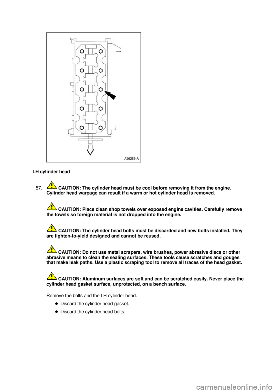
LH cylinder head
57. CAUTION: The cylinder head must be cool before removing it from the engine.
Cylinder head warpage can result if a warm or hot cylinder head is removed.
CAUTION: Place clean shop towels over exposed engine cavities. Carefully remove
the towels so foreign material is not dropped into the engine.
CAUTION: The cylinder head bolts must be discarded and new bolts installed. They
are tighten- to-yield designed and cannot be reused.
CAUTION: Do not use metal scrapers, wire brushes, power abrasive discs or other
abrasive means to clean the sealing surfaces. These tools cause scratches and gouges
that make leak paths. Use a plastic scraping tool to remove all traces of the head gasket.
CAUTION: Aluminum surfaces are soft and can be scratched easily. Never place the
cylinder head gasket surface, unprotected, on a bench surface.
Remove the bolts and the LH cylinder head.
�zDiscard the cylinder head gasket.
�z Discard the cylinder head bolts. �K�l�j . 19 �b�a
212003 Mustang Workshop Manual
17. 11. 2011file:///C:/Ford/2000 - 2004/tsocache/SHEF_4464/S3B~us~en~ ...
Page 1302 of 4378
DISASSEMBLY AND ASSEMBLY OF SUBASSEMBLIES
Piston
Disassembly
1. Press the piston pin out of the connecting rod and piston assembly.
2. Remove the connecting rod from the piston.
3. Clean and inspect the piston and connecting rod. For additional information, refer to Section 303 - 00 .
Assembly 1. NOTE: Connecting rod must be installed into piston with identification markings toward front.
Position the connecting rod in the piston.
SECTION 303-
01B: Engine — 4.6L (2V) 2003 Mustang Workshop Manual Material
Item Specification
Super Premium SAE 5W-20
Motor Oil
XO- 5W20- QSP or equivalent WSS-
M2C153-
H �K�l�j . 1 �b�a
32003 Mustang Workshop Manual
17. 11. 2011file:///C:/Ford/2000 - 2004/tsocache/SHEF_4464/S3B~us~en~ ...
Page 1303 of 4378
2. Press the piston into the piston and connecting rod assembly.
3. Install the piston rings.
1. Using a suitable ring expander tool install the upper compression ring with the top side identification mark towards the dome.
2. Using a suitable ring expander tool install the lower compression ring with the top side
identification mark towards the dome.
3. NOTE: Assemble with end gaps up.
Using a suitable tool install the piston oil control segment ring spacer.
4. NOTE: Install one segment ring above and one segment ring below the spacer.
Using a suitable tool install the piston oil control segment rings.
5. Orient the upper compression ring gap to the center line at the rear of the piston, parallel to the wrist pin bore.
6. Orient the oil control ring gaps as shown.
7. Orient the expander ring gap and lower compression ring gap as shown. �K�l�j . 2 �b�a
32003 Mustang Workshop Manual
17. 11. 2011file:///C:/Ford/2000 - 2004/tsocache/SHEF_4464/S3B~us~en~ ...
Page 1310 of 4378
7.
NOTE: The oil groove on the thrust washer must face toward the rear of the engine (against the
crankshaft surface).
Push the crankshaft rearward and install the crankshaft upper thrust washer at the rear of the
No. 5 main boss.
8. NOTE: Rotate the jackscrews into the bearing caps enough to provide clearance to the cylinder
block prior to installing the bearing caps.
Install the lower main bearings into the main bearing caps and lubricate them with clean engine
oil.
9. Install the rear main bearing cap.
10. Install the remaining main bearing caps on the cylinder block and tap into place using a plastic or dead- blow hammer. �K�l�j . 6 �b�a
362003 Mustang Workshop Manual
17. 11. 2011file:///C:/Ford/2000 - 2004/tsocache/SHEF_4464/S3B~us~en~ ...
Page 1545 of 4378
4. Clean and inspect the piston and connecting rod. For additional information, refer to
Section 303 - 00 .
Assembly 1. NOTE: Connecting rod must be installed into piston with identification markings toward front.
Position the connecting rod in the piston.
2. Lubricate the piston pin and pin bore with clean engine oil.
3. Install the piston pin in the piston and connecting rod assembly. �K�l�j . 2 �b�a
32003 Mustang Workshop Manual
17. 11. 2011file:///C:/Ford/2000 - 2004/tsocache/SHEF_4464/S3B~us~en~ ...