Page 3869 of 4378

Washers
When the GEM detects the ignition switch circuits are in RUN or ACC states, and the GEM detects a
WASH request from the wiper delay/wash circuits, the GEM will activate the washer pump relay circuit
for as long as the request is present up to 10 seconds.
Activation of the washer pump when in INTERVAL or OFF is delayed until a wash request is active for
a minimum amount of time. In this scenario, the wash request must be present continuously for at least
210 ms. This allows a wash request that is present for less than 210 ms, to provide additional
functionality by initiating a single wipe, called "mist wipe". The mist wipe function is a single wipe at low
speed without activating the washer motor.
When in LOW or HIGH, any WASH request, regardless of the length of time it is present, will activate
the washer pump. When in INTERVAL or OFF mode, upon deactivation of the washer motor, this
feature shall provide two wipes at low speed before returning to the INTERVAL or OFF state as
defined by the inputs. These additional wipes are provided to clear residual washer fluid from the front
windshield.
Inspection and Verification
1. Verify the customer concern by operating the wiper/washer system.
2. Visually inspect for obvious signs of mechanical and electrical damage.
3. If the concern remains after the inspection, connect the diagnostic tool to the data link connector (DLC) located beneath the instrument panel and select the vehicle to be tested from the
diagnostic tool menu. If diagnostic tool does not communicate with the vehicle:
�zCheck that the program card is correctly installed.
�z Check the connections to the vehicle.
�z Check the ignition switch position.
4. If diagnostic tool still does not communicate with the vehicle, refer to the diagnostic tool manual.
5. Carry out the DATA LINK DIAGNOSTIC TEST. If diagnostic tool responds with: �zCKT914, CKT915 or CKT70 = ALL ECUS NO RESP/NOT EQUIP, refer to Section 418 -
00 .
�z NO RESPONSE/NOT EQUIPPED for GEM, go to Pinpoint Test A.
�z SYSTEM PASSED, retrieve and record the continuous diagnostic trouble codes (DTCs),
erase the continuous DTCs and carry out self- test diagnostics for the GEM.
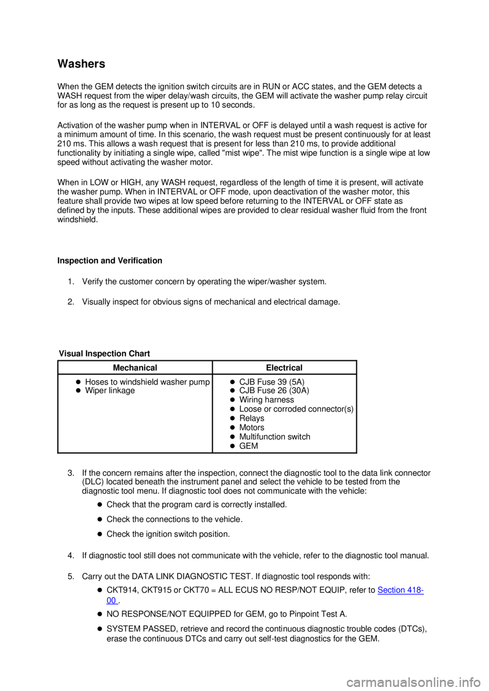
Visual Inspection Chart Mechanical Electrical
�z
Hoses to windshield washer pump
�z Wiper linkage �z
CJB Fuse 39 (5A)
�z CJB Fuse 26 (30A)
�z Wiring harness
�z Loose or corroded connector(s)
�z Relays
�z Motors
�z Multifunction switch
�z GEM �K�l�j . 2 �b�a
202003 Mustang Workshop Manual
18. 11. 2011file:///C:/Ford/2000 - 2004/tsocache/SHEF_5108/S3B~us~en~ ...
Page 3919 of 4378

GENERAL PROCEDURES
Linkage Adjustment
NOTE:
Before starting the adjustment process, inspect the top for damage, make sure that the door
window glass and rear quarter glass are correctly adjusted then completely lower all window glass.
NOTE: After each adjustment make sure the convertible top operates correctly.
The Convertible Top Dowel Pins Fall Forward (Overshoot) or Rearward (Undershoot). The
Receiver Cups — Cam Bolt Adjustment.
1. Remove the quarter trim panel. For additional information, refer to Section 501 - 05 .
2. Close the convertible top and examine the position of the dowel pins relative to the receiver cups.
3. Move the convertible top to the half- open position to access the cam bolt.
4. NOTE: Rotating the top of the cam bolt toward the front of the vehicle will lengthen the top, increase the tension on the top and increase pull - down effort. Rotating the cam bolt in the SECTION 501-
18: Convertible Top 2003 Mustang Workshop Manual Material
Item Specification
Threadlock and
Sealer
E0AZ-
19554- AA WSK-
M2G351- A5 (type
II) Shoulder Bolt Kit
F5ZZ-
76539A04- A — �K�l�j . 1 �b�a
72003 Mustang Workshop Manual
18. 11. 2011file:///C:/Ford/2000 - 2004/tsocache/SHEF_5108/S3B~us~en~ ...
Page 3940 of 4378
11. Remove all of the staples in the rear window glass assembly along the number four bow.
12. Remove the rear window glass assembly.
Installation 1. Overlay the new rear window glass assembly over the old rear window glass assembly and transpose the markings with a grease pencil.
2. Center the V- notch on the new rear window glass assembly to the center mark on the top of the
number four bow.
3. Align the rear window glass assembly to the top groove of the number four bow and staple the entire length. �K�l�j . 3 �b�a
62003 Mustang Workshop Manual
18. 11. 2011file:///C:/Ford/2000 - 2004/tsocache/SHEF_5108/S3B~us~en~ ...
Page 3942 of 4378
8. Align the center line mark on the cover assembly to the V-
notch on the rear window glass
assembly and staple the entire length.
9. Align the top edge of the quarter tacking strip to the reference line on the convertible top cover and staple.
10. Install the tacking strips over the body studs.
11. Tighten the tacking strip nuts.
12. Install the well sling. �K�l�j . 5 �b�a
62003 Mustang Workshop Manual
18. 11. 2011file:///C:/Ford/2000 - 2004/tsocache/SHEF_5108/S3B~us~en~ ...
Page 3948 of 4378
20. Remove the staples.
21.
NOTE: All adhesive tape must be removed from the folding roof rear side rail.
Pull the roof outside cover flaps to disengage from each folding roof rear side rail.
22. Remove the staples from the entire length of the number four bow.
23. Disengage the cable from each side. �K�l�j . 5 �b�a
132003 Mustang Workshop Manual
18. 11. 2011file:///C:/Ford/2000 - 2004/tsocache/SHEF_5108/S3B~us~en~ ...
Page 3949 of 4378
24. Remove the cable from the cover assembly.
25.
NOTE: The cable is spring- loaded. Use care not to lose the cable end during disassembly.
Disconnect the trim tension cable.
26. Remove the cover from the frame.
Installation 1. Align the center mark on the cover assembly to the V- notch on the rear glass assembly and
staple the entire length of the number four bow. �K�l�j . 6 �b�a
132003 Mustang Workshop Manual
18. 11. 2011file:///C:/Ford/2000 - 2004/tsocache/SHEF_5108/S3B~us~en~ ...
Page 3980 of 4378

�z
If the driver safety belt is buckled while the warning indicator is illuminated and the reminder
chime is sounding, then the safety belt warning indicator and reminder chime turn off.
�z If the driver safety belt is buckled before the ignition switch is turned to ON, then the safety belt
warning light will turn on for 3 seconds and then off. The indicator chime will remain off.
Belt Minder (if equipped)
The Belt Minder feature is a supplemental warning to the safety belt warning function. This feature
provides additional reminders to the driver that the driver's safety belt is unbuckled by intermittently
sounding a chime and illuminating the safety belt warning lamp in the instrument cluster.
Safety Belt Extension
A safety belt that is too short even when fully extended can be lengthened. The safety belt extension
(611C22) is available. This assembly will add approximately 20 cm (8 inches) to the length of the
safety belt. Use the safety belt extension only if the safety belt is too short when fully extended. Do not
use the safety belt extension to alter the fit of the shoulder belt across the torso. Safety belt extensions
are available at no cost from any authorized Ford or Lincoln- Mercury dealer.
Lower Anchors and Tethers for Children (LATCH)
The lower anchors and tethers for children (LATCH) system is a standarized and uniform attachment
system for installing child safety seats in passenger vehicles. LATCH- equipped child safety seats have
two lower attachments that connect to the vehicle portion of the LATCH system.
The vehicle portion of the system consists of two attachment points (6- mm wires) bolted to the floor
pan at both second row outboard seating positions. The attachment points protrude from the biteline
between the seat cushion and seat backrest.
If a child safety seat was in use during a collision, inspect the vehicle portion of the system for
damage. If any of the attachment points (6- mm wires) are damaged, a new one must be installed. See
the appropriate removal and installation procedure in this section for service.
Attaching Safety Seats with Tether Straps
Some manufacturers make child safety seats that include a tether strap that goes over the back of the
vehicle seat and attaches to an anchoring point. Other manufacturers offer the tether strap as an
accessory. Contact the manufacturer of the child safety seat for information about ordering a tether
strap. If... Then...
The driver's safety belt is not buckled
approximately 5 seconds after the safety
belt warning light has turned off... The Belt Minder feature is activated —
the safety belt
warning light illuminates and the warning chime sounds for
6 seconds every 30 seconds, repeating for approximately
5 minutes or until safety belt is buckled. The driver's safety belt is buckled while
the safety belt indicator light is
illuminated and the safety belt warning
chime is sounding... The Belt Minder feature will not activate.
The driver's safety belt is buckled before
the ignition switch is turned to the ON
position... The Belt Minder feature will not activate. �K�l�j . 2 �b�a
32003 Mustang Workshop Manual
18. 11. 2011file:///C:/Ford/2000 - 2004/tsocache/SHEF_5108/S3B~us~en~ ...
Page 3989 of 4378

GENERAL PROCEDURES
Replacement of the Weld Nut and Reinforcement
1. NOTE: The following is for Coupe, Front and Rear, and Convertible rear only.
NOTE: If the safety belt anchor nuts or reinforcements are stripped or missing, a new
nut/reinforcement plate must be installed.
Expose the suspect anchor point.
2. Drill out two 8 mm (0.32 in) (5/16 inch) diameter access holes adjacent to the weld nut clearance hole.
3. Thread a length of copper welding wire through the clearance hole and position to secure the weld nut and washer.
4. Use MIG wire feed welder and plug weld a 7/16 inch weld nut and standard washer in place at the two 8 mm (5/16 inch) holes.
5. Metal finish as necessary.
6. Install the restraint system.
7. Carry out the Functional Test. For additional information, refer to Safety Belt System in this
section.
SECTION 501-
20A: Safety Belt System 2003 Mustang Workshop Manual �K�l�j . 1 �b�a
12003 Mustang Workshop Manual
18. 11. 2011file:///C:/Ford/2000 - 2004/tsocache/SHEF_5108/S3B~us~en~ ...