Page 1605 of 4378

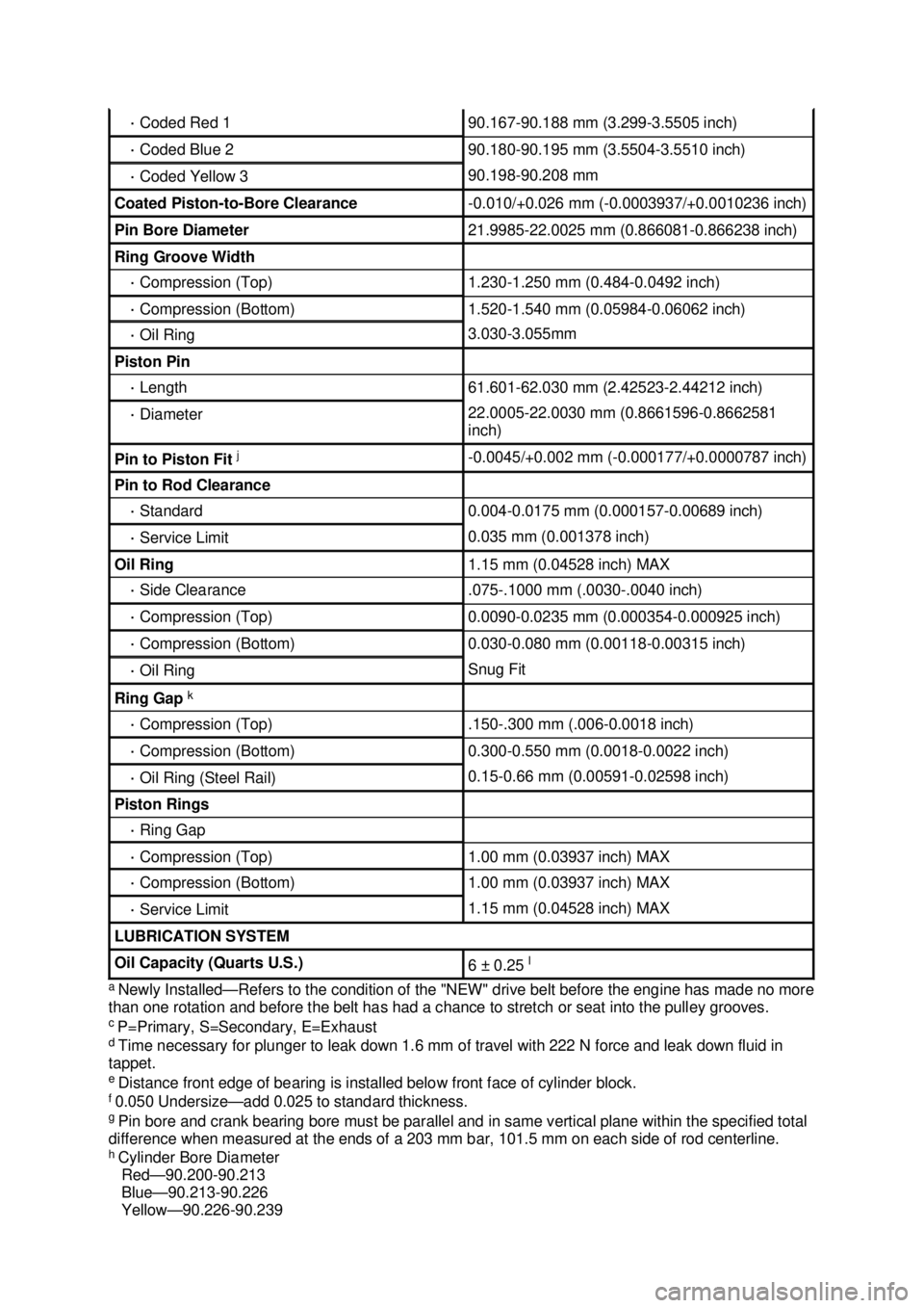
a
Newly Installed— Refers to the condition of the "NEW" drive belt before the engine has made no more
than one rotation and before the belt has had a chance to stretch or seat into the pulley grooves.
c P=Primary, S=Secondary, E=Exhaust
d Time necessary for plunger to leak down 1.6 mm of travel with 222 N force and leak down fluid in
tappet.
e Distance front edge of bearing is installed below front face of cylinder block.
f 0.050 Undersize— add 0.025 to standard thickness.
g Pin bore and crank bearing bore must be parallel and in same vertical plane within the specified total
difference when measured at the ends of a 203 mm bar, 101.5 mm on each side of rod centerline.
h Cylinder Bore Diameter
Red— 90.200-90.213
Blue— 90.213-90.226
Yellow— 90.226-90.239 ·
Coded Red 1 90.167-
90.188 mm (3.299- 3.5505 inch) ·
Coded Blue 2 90.180-
90.195 mm (3.5504- 3.5510 inch) ·
Coded Yellow 3 90.198-
90.208 mm Coated Piston-
to-Bore Clearance -
0.010/+0.026 mm (- 0.0003937/+0.0010236 inch) Pin Bore Diameter 21.9985-
22.0025 mm (0.866081- 0.866238 inch) Ring Groove Width
·
Compression (Top) 1.230-
1.250 mm (0.484- 0.0492 inch) ·
Compression (Bottom) 1.520-
1.540 mm (0.05984- 0.06062 inch) ·
Oil Ring 3.030-
3.055mm Piston Pin
·
Length 61.601-
62.030 mm (2.42523- 2.44212 inch) ·
Diameter 22.0005-
22.0030 mm (0.8661596- 0.8662581
inch) Pin to Piston Fit
j -
0.0045/+0.002 mm (- 0.000177/+0.0000787 inch) Pin to Rod Clearance
·
Standard 0.004-
0.0175 mm (0.000157- 0.00689 inch) ·
Service Limit 0.035 mm (0.001378 inch)
Oil Ring 1.15 mm (0.04528 inch) MAX
·
Side Clearance .075
-.1000 mm (.0030 -.0040 inch) ·
Compression (Top) 0.0090-
0.0235 mm (0.000354- 0.000925 inch) ·
Compression (Bottom) 0.030-
0.080 mm (0.00118- 0.00315 inch) ·
Oil Ring Snug Fit
Ring Gap
k ·
Compression (Top) .150
-.300 mm (.006- 0.0018 inch) ·
Compression (Bottom) 0.300-
0.550 mm (0.0018- 0.0022 inch) ·
Oil Ring (Steel Rail) 0.15-
0.66 mm (0.00591- 0.02598 inch) Piston Rings
·
Ring Gap ·
Compression (Top) 1.00 mm (0.03937 inch) MAX
·
Compression (Bottom) 1.00 mm (0.03937 inch) MAX
·
Service Limit 1.15 mm (0.04528 inch) MAX
LUBRICATION SYSTEM
Oil Capacity (Quarts U.S.)
6 ±
0.25 l �K�l�j . 4 �b�a
62003 Mustang Workshop Manual
17. 11. 2011file:///C:/Ford/2000 - 2004/tsocache/SHEF_4464/S3B~us~en~ ...
Page 1681 of 4378
7.
CAUTION: The bolts are different lengths and must be returned to their original
location.
NOTE: RH shown; LH similar.
Remove the bolts and the timing chain guides.
Installation 1. CAUTION: Timing chain procedures must be followed exactly or damage to the
pistons or valves will result.
Compress the tensioner plunger, using a soft- jawed vise.
2. Install a retaining clip on the tensioner to hold the plunger in during installation. �zRemove the tensioner from the vise. �K�l�j . 3 �b�a
72003 Mustang Workshop Manual
17. 11. 2011file:///C:/Ford/2000 - 2004/tsocache/SHEF_4464/S3B~us~en~ ...
Page 2566 of 4378
42. Install the 1-
2 accumulator retaining ring.
43. NOTE: This is not an ordinary installation procedure and does not compensate for band wear.
When new piston and rod assembly installation becomes necessary, or when a new reverse
band has been installed, the reverse piston and rod length must be adjusted.
NOTE: Lubricate the reverse piston seal to facilitate assembly and prevent damage to the seal.
NOTE: Do not install the reverse servo piston cover and seal at this time.
Install the reverse servo piston and rod assembly.
44. Install the special tool. �zTighten the bolt. �K�l�j . 15 �b�a
252003 Mustang Workshop Manual
18. 11. 2011file:///C:/Ford/2000 - 2004/tsocache/SHEF_2748/S3B~us~en~ ...
Page 2724 of 4378
1. Using the special tool, install the input shaft seal.
2.
NOTE: In installing a new input shaft seal as part of a transmission overhaul, do not install the
end play selective shims at this time.
Instal the end play selective shims and the bearing race.
3. Using a press and a capped length of pipe, install the input bearing. �K�l�j . 2 �b�a
32003 Mustang Workshop Manual
18. 11. 2011file:///C:/Ford/2000 - 2004/tsocache/SHEF_2308/S3B~us~en~ ...
Page 2733 of 4378
13. Install the output shaft rear bearing.
14. Lubricate the splines of the fifth speed driven gear with petroleum jelly.
15.
CAUTION: Align the output shaft splines and the splines of the fifth speed driven
gear or damage will occur.
Position the fifth speed driven gear on the output shaft. Using a press and a capped length of
pipe 31.7 mm (1.26 in) inside diameter X 356 mm (14.24 in) long, install the fifth speed driven
gear.
16. Install the snap ring. �K�l�j . 8 �b�a
102003 Mustang Workshop Manual
18. 11. 2011file:///C:/Ford/2000 - 2004/tsocache/SHEF_2308/S3B~us~en~ ...
Page 3096 of 4378
tool to prevent axial scratches which may cause future leaks.
Polish for one minute at moderate speed (less than 1,500 rpm) or until the surface is clean and
free of scratches or foreign material.
7. Clean the fitting with a lint- free cloth.
8. Inspect the surface for grooves or scratches. If grooves and scratches are still present, install a new component.
9. Clean the O- ring seal grooves with a 300 mm (12 inch) length of natural fiber string.
�z Loop the string around the grooves and pull the string back and forth.
10. Remove any foreign material from the grooves with a lint- free cloth.
Connect 1. Install the A/C tube lock coupling spring.
2. Lubricate the inside of the coupling with PAG Refrigerant Compressor Oil (R- 134a Systems) or
equivalent. �K�l�j . 4 �b�a
62003 Mustang Workshop Manual
18. 11. 2011file:///C:/Ford/2000 - 2004/tsocache/SHEF_2308/S3B~us~en~ ...
Page 3133 of 4378

GENERAL PROCEDURES
Vacuum Hose Repair —
Mini-Tube
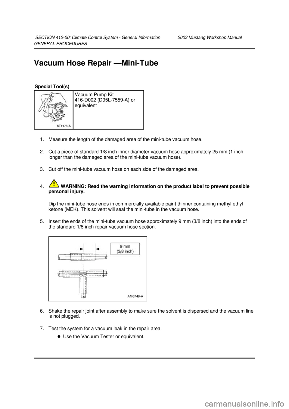
1. Measure the length of the damaged area of the mini-tube vacuum hose.
2. Cut a piece of standard 1/8 inch inner diameter vacuum hose approximately 25 mm (1 inch longer than the damaged area of the mini- tube vacuum hose).
3. Cut off the mini-tube vacuum hose on each side of the damaged area.
4. WARNING: Read the warning information on the product label to prevent possible
personal injury.
Dip the mini- tube hose ends in commercially available paint thinner containing methyl ethyl
ketone (MEK). This solvent will seal the mini- tube in the vacuum hose.
5. Insert the ends of the mini- tube vacuum hose approximately 9 mm (3/8 inch) into the ends of
the standard 1/8 inch repair vacuum hose section.
6. Shake the repair joint after assembly to make sure the solvent is dispersed and the vacuum line is not plugged.
7. Test the system for a vacuum leak in the repair area. �zUse the Vacuum Tester or equivalent.
SECTION 412-
00: Climate Control System - General Information 2003 Mustang Workshop Manual Special Tool(s)
Vacuum Pump Kit
416-
D002 (D95L-7559- A) or
equivalent �K�l�j . 1 �b�a
22003 Mustang Workshop Manual
18. 11. 2011file:///C:/Ford/2000 - 2004/tsocache/SHEF_2308/S3B~us~en~ ...
Page 3521 of 4378
SPECIFICATIONS
SECTION 418-
00: Module Communications Network 2003 Mustang Workshop Manual General Specifications
Item Specification
Heat shrink tube overlap mm (inch) 12.7 (0.5)
Wire insulation removal length (twist side) mm (inch) 37.2 (1.5)
Wire insulation removal length (receiving side) mm (inch) 19.5 (0.75)
Raychem SCT® Heat Shrink Tubing, Motorcraft part number WT-
5627 ESB-
M99D56-A2 �K�l�j . 1 �b�a
12003 Mustang Workshop Manual
18. 11. 2011file:///C:/Ford/2000 - 2004/tsocache/SHEF_5108/S3B~us~en~ ...