Page 3584 of 4378
Installation
1. NOTE: When the is battery disconnected and reconnected, some abnormal drive symptoms
may occur while the vehicle relearns its adaptive strategy. The vehicle may need to be driven
16 km (10 miles) or more to relearn the strategy.
To install, reverse the removal procedure. �K�l�j . 3 �b�a
42003 Mustang Workshop Manual
18. 11. 2011file:///C:/Ford/2000 - 2004/tsocache/SHEF_5108/S3B~us~en~ ...
Page 3586 of 4378
SPECIFICATIONS
SECTION 419-
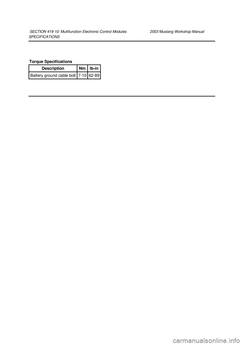
10: Multifunction Electronic Control Modules 2003 Mustang Workshop Manual Torque Specifications
Description Nm lb-
in Battery ground cable bolt 7-
10 62-89 �K�l�j . 1 �b�a
12003 Mustang Workshop Manual
18. 11. 2011file:///C:/Ford/2000 - 2004/tsocache/SHEF_5108/S3B~us~en~ ...
Page 3587 of 4378
DESCRIPTION AND OPERATION
Module Controlled Functions
The generic electronic module (GEM)(14B205) is the only multifunction control module on this vehicle.
The GEM controls the following functions:
�zwarning chimes and warning lamps
�z one- touch down window
�z windshield washers and wipers
�z battery saver
�z illuminated entry with keyless remote entry
�z interior lighting
SECTION 419-
10: Multifunction Electronic Control Modules 2003 Mustang Workshop Manual �K�l�j . 1 �b�a
12003 Mustang Workshop Manual
18. 11. 2011file:///C:/Ford/2000 - 2004/tsocache/SHEF_5108/S3B~us~en~ ...
Page 3588 of 4378
DIAGNOSIS AND TESTING
Multifunction Electronic Module
For warning chime concerns, refer to
Section 413 - 09 .
For courtesy lamps/illuminated entry and battery saver concerns, refer to Section 417 - 02 .
For one- touch window concerns, refer to Section 501 - 11 .
For wiper/washer control and interval timer concerns, refer to Section 501 - 16 .
For keyless entry and power door lock concerns, refer to Section 501 - 14B .
For anti- theft concerns, refer to Section 419 - 01 .
SECTION 419-
10: Multifunction Electronic Control Modules 2003 Mustang Workshop Manual �K�l�j . 1 �b�a
12003 Mustang Workshop Manual
18. 11. 2011file:///C:/Ford/2000 - 2004/tsocache/SHEF_5108/S3B~us~en~ ...
Page 3589 of 4378
REMOVAL AND INSTALLATION
Module —
Generic Electronic (GEM)
Removal
1. CAUTION: Electronic modules are sensitive to static electrical charges. If exposed
to these charges, damage may result.
Disconnect the battery ground cable (14301).
2. Remove the generic electronic module (GEM)(14B205). 1. Remove the five electrical connectors.
2. Release the locking tab and slide the module off the bracket.
Installation 1. NOTE: When the battery (10655) is disconnected and reconnected, some abnormal drive
symptoms may occur while the vehicle relearns its adaptive strategy. The vehicle may need to
be driven 10 mile s (16 km) or more to relearn the strategy.
To install, reverse the removal procedure.
SECTION 419-
10: Multifunction Electronic Control Modules 2003 Mustang Workshop Manual �K�l�j . 1 �b�a
22003 Mustang Workshop Manual
18. 11. 2011file:///C:/Ford/2000 - 2004/tsocache/SHEF_5108/S3B~us~en~ ...
Page 3667 of 4378

DIAGNOSIS AND TESTING
Seats
Refer to Wiring Diagrams Cell
120 , Power Seats for schematic and connector information.
Refer to Wiring Diagrams Cell 122 , Power Lumbar Seats for schematic and connector information.
Inspection and Verification 1. Verify the customer concern by operating the system.
2. Visually inspect for obvious signs of mechanical or electrical damage.
3. If an obvious cause for an observed or reported concern is found, correct the cause (if possible) before proceeding to the next step.
4. If the concern is not visually evident, verify the symptom. GO to Symptom Chart .
Symptom Chart
Refer to the Wiring Diagram manual for the connector numbers cited in the pinpoint tests. SECTION 501-
10: Seating 2003 Mustang Workshop Manual Special Tool(s)
73 III Automotive Meter
105-
R0057
Visual Inspection Chart Mechanical Electrical
�z
Front seat track.
�z Seat at limit(s) of travel. �z
Battery junction box (BJB) Fuse Power Seat (25A).
�z Loose, corroded or damaged connectors.
�z Seat regulator control switch.
�z Lumbar seat control switch.
�z Lumbar motor.
�z Bolster and lumbar control switches (cobra)
SYMPTOM CHART Condition
Possible Sources Action
�z The power seat is
inoperative �z
BJB Fuse Power Seat
(25A).
�z Seat regulator control
switch.
�z Circuitry. �z
Go To Pinpoint Test
A . �K�l�j . 1 �b�a
152003 Mustang Workshop Manual
18. 11. 2011file:///C:/Ford/2000 - 2004/tsocache/SHEF_5108/S3B~us~en~ ...
Page 3682 of 4378
REMOVAL AND INSTALLATION
Switch —
Seat Regulator Control
Removal and Installation 1. Disconnect the battery. For additional information, refer to Section 414 - 01 .
2. Remove the screws and position the seat regulator control switch aside.
3. Disconnect the electrical connector and remove the seat regulator control switch.
4. To install, reverse the removal procedure.
SECTION 501-
10: Seating 2003 Mustang Workshop Manual �K�l�j . 1 �b�a
22003 Mustang Workshop Manual
18. 11. 2011file:///C:/Ford/2000 - 2004/tsocache/SHEF_5108/S3B~us~en~ ...
Page 3692 of 4378
REMOVAL AND INSTALLATION
Seat —
Front Power
Removal and Installation 1. Remove the safety belt through the opening in the safety belt guide.
2. Move the seat forward.
3. Remove the bolt covers and remove the seat track bolts.
4. Move the seat rearward.
5. Remove the seat track nuts.
6. Move the seat forward.
7. Disconnect the battery. For additional information, refer to Section 414 - 01 .
SECTION 501-
10: Seating 2003 Mustang Workshop Manual �K�l�j . 1 �b�a
22003 Mustang Workshop Manual
18. 11. 2011file:///C:/Ford/2000 - 2004/tsocache/SHEF_5108/S3B~us~en~ ...

(14B205) is the only multifunction control module on this vehicle.
The GEM controls the following functions:")


Removal
1. CAUTION: Electronic modules are sensitive to static electrical charges. If exposed
to these charges, damage may result.
Di")

