Page 944 of 4378
Engine Components Item Part Number Description
1 6B288 Camshaft position sensor
2 8507 Water pump housing gasket
3 12A362 Camshaft synchronizer
4 6A618 Oil pump intermediate shaft
5 6020 Engine front cover gasket
6 6010 Cylinder block
7 6019 Engine front cover
8 6714 Oil bypass filter
9 6C315 Crankshaft position sensor
10 8501 Water pump
11 6312 Crankshaft pulley �K�l�j . 3 �b�a
82003 Mustang Workshop Manual
17. 11. 2011file:///C:/Ford/2000 - 2004/tsocache/SHEF_4464/S3B~us~en~ ...
Page 980 of 4378
12. Disconnect the crankshaft position sensor electrical connector.
13. Remove the wiring harness pin-
type retainer.
14. Remove the oil filter.
15. Remove the retainers and the water pump. �K�l�j . 3 �b�a
92003 Mustang Workshop Manual
17. 11. 2011file:///C:/Ford/2000 - 2004/tsocache/SHEF_4464/S3B~us~en~ ...
Page 983 of 4378
6.
NOTE: The number 12 bolt is not part of the tightening sequence.
Tighten the fasteners to 26 Nm (19 lb- ft) in the sequence shown.
7. Install a new oil filter.
8. Install the wiring harness pin- type retainer. �K�l�j . 6 �b�a
92003 Mustang Workshop Manual
17. 11. 2011file:///C:/Ford/2000 - 2004/tsocache/SHEF_4464/S3B~us~en~ ...
Page 1132 of 4378

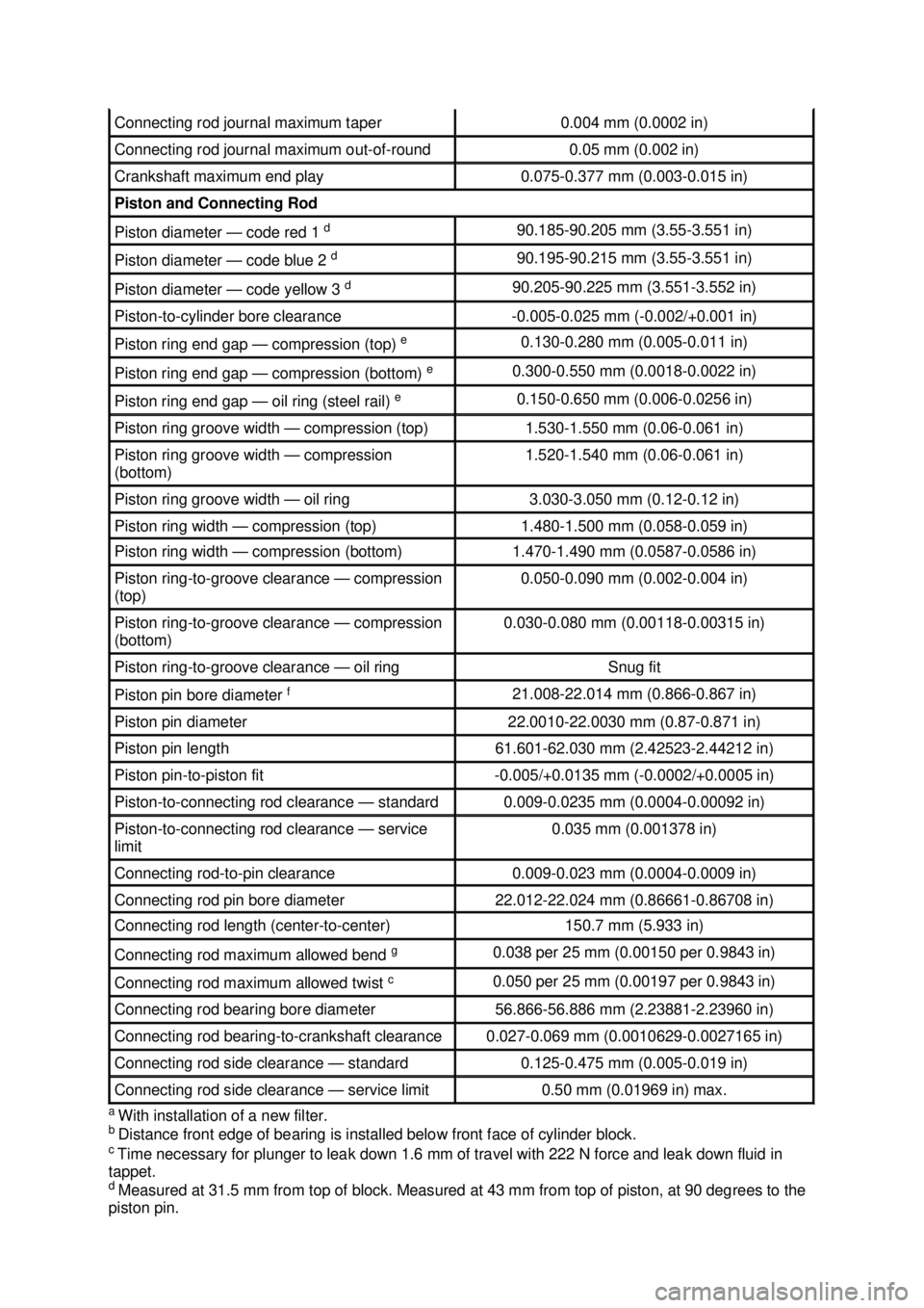
a
With installation of a new filter.
b Distance front edge of bearing is installed below front face of cylinder block.
c Time necessary for plunger to leak down 1.6 mm of travel with 222 N force and leak down fluid in
tappet.
d Measured at 31.5 mm from top of block. Measured at 43 mm from top of piston, at 90 degrees to the
piston pin. Connecting rod journal maximum taper 0.004 mm (0.0002 in)
Connecting rod journal maximum out-of-
round 0.05 mm (0.002 in)
Crankshaft maximum end play 0.075-
0.377 mm (0.003- 0.015 in) Piston and Connecting Rod
Piston diameter —
code red 1 d 90.185-
90.205 mm (3.55- 3.551 in) Piston diameter —
code blue 2 d 90.195-
90.215 mm (3.55- 3.551 in) Piston diameter —
code yellow 3 d 90.205-
90.225 mm (3.551- 3.552 in) Piston-
to-cylinder bore clearance -0.005-
0.025 mm (- 0.002/+0.001 in) Piston ring end gap —
compression (top) e 0.130-
0.280 mm (0.005- 0.011 in) Piston ring end gap —
compression (bottom) e 0.300-
0.550 mm (0.0018- 0.0022 in) Piston ring end gap —
oil ring (steel rail) e 0.150-
0.650 mm (0.006- 0.0256 in) Piston ring groove width —
compression (top) 1.530-
1.550 mm (0.06- 0.061 in) Piston ring groove width —
compression
(bottom) 1.520-
1.540 mm (0.06- 0.061 in) Piston ring groove width —
oil ring 3.030-
3.050 mm (0.12- 0.12 in) Piston ring width —
compression (top) 1.480-
1.500 mm (0.058- 0.059 in) Piston ring width —
compression (bottom) 1.470-
1.490 mm (0.0587- 0.0586 in) Piston ring-
to-groove clearance — compression
(top) 0.050-
0.090 mm (0.002- 0.004 in) Piston ring-
to-groove clearance — compression
(bottom) 0.030-
0.080 mm (0.00118- 0.00315 in) Piston ring-
to-groove clearance — oil ring Snug fit
Piston pin bore diameter
f 21.008-
22.014 mm (0.866- 0.867 in) Piston pin diameter 22.0010-
22.0030 mm (0.87- 0.871 in) Piston pin length 61.601-
62.030 mm (2.42523- 2.44212 in) Piston pin-
to-piston fit -
0.005/+0.0135 mm (- 0.0002/+0.0005 in) Piston-
to-connecting rod clearance — standard 0.009-
0.0235 mm (0.0004- 0.00092 in) Piston-
to-connecting rod clearance — service
limit 0.035 mm (0.001378 in)
Connecting rod-
to-pin clearance 0.009-
0.023 mm (0.0004- 0.0009 in) Connecting rod pin bore diameter 22.012-
22.024 mm (0.86661- 0.86708 in) Connecting rod length (center-
to-center) 150.7 mm (5.933 in)
Connecting rod maximum allowed bend
g 0.038 per 25 mm (0.00150 per 0.9843 in)
Connecting rod maximum allowed twist
c 0.050 per 25 mm (0.00197 per 0.9843 in)
Connecting rod bearing bore diameter 56.866-
56.886 mm (2.23881- 2.23960 in) Connecting rod bearing-
to-crankshaft clearance 0.027-
0.069 mm (0.0010629- 0.0027165 in) Connecting rod side clearance —
standard 0.125-
0.475 mm (0.005- 0.019 in) Connecting rod side clearance —
service limit 0.50 mm (0.01969 in) max. �K�l�j . 3 �b�a
62003 Mustang Workshop Manual
17. 11. 2011file:///C:/Ford/2000 - 2004/tsocache/SHEF_4464/S3B~us~en~ ...
Page 1133 of 4378

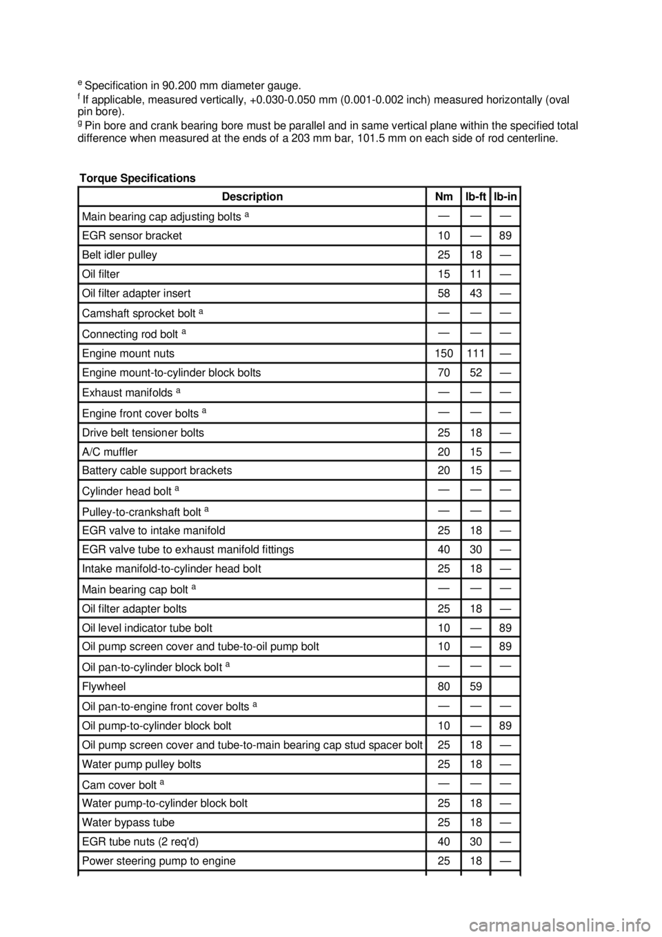
e
Specification in 90.200 mm diameter gauge.
f If applicable, measured vertically, +0.030- 0.050 mm (0.001-0.002 inch) measured horizontally (oval
pin bore).
g Pin bore and crank bearing bore must be parallel and in same vertical plane within the specified total
difference when measured at the ends of a 203 mm bar, 101.5 mm on each side of rod centerline.
Torque Specifications Description Nm lb-
ft lb-
in Main bearing cap adjusting bolts
a — — —
EGR sensor bracket 10 — 89
Belt idler pulley 25 18 —
Oil filter 15 11 —
Oil filter adapter insert 58 43 —
Camshaft sprocket bolt
a — — —
Connecting rod bolt
a — — —
Engine mount nuts 150 111 —
Engine mount-
to-cylinder block bolts 70 52 —
Exhaust manifolds
a — — —
Engine front cover bolts
a — — —
Drive belt tensioner bolts 25 18 —
A/C muffler 20 15 —
Battery cable support brackets 20 15 —
Cylinder head bolt
a — — —
Pulley-
to-crankshaft bolt a — — —
EGR valve to intake manifold 25 18 —
EGR valve tube to exhaust manifold fittings 40 30 —
Intake manifold-
to-cylinder head bolt 25 18 —
Main bearing cap bolt
a — — —
Oil filter adapter bolts 25 18 —
Oil level indicator tube bolt 10 — 89
Oil pump screen cover and tube-
to-oil pump bolt 10 — 89
Oil pan-to-
cylinder block bolt a — — —
Flywheel 80 59
Oil pan-to-
engine front cover bolts a — — —
Oil pump-
to-cylinder block bolt 10 — 89
Oil pump screen cover and tube-
to-main bearing cap stud spacer bolt 25 18 —
Water pump pulley bolts 25 18 —
Cam cover bolt
a — — —
Water pump-
to-cylinder block bolt 25 18 —
Water bypass tube 25 18 —
EGR tube nuts (2 req'd) 40 30 —
Power steering pump to engine 25 18 — �K�l�j . 4 �b�a
62003 Mustang Workshop Manual
17. 11. 2011file:///C:/Ford/2000 - 2004/tsocache/SHEF_4464/S3B~us~en~ ...
Page 1139 of 4378

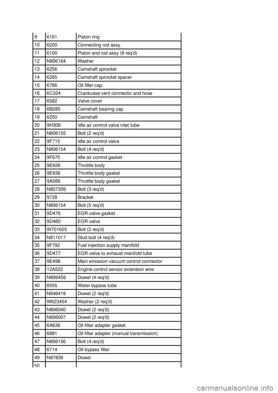
9 6161 Piston ring
10 6200 Connecting rod assy.
11 6100 Piston and rod assy (8 req'd)
12 N806164 Washer
13 6256 Camshaft sprocket
14 6265 Camshaft sprocket spacer
15 6766 Oil filler cap
16 6C324 Crankcase vent connector and hose
17 6582 Valve cover
18 6B280 Camshaft bearing cap
19 6250 Camshaft
20 9H308 Idle air control valve inlet tube
21 N806155 Bolt (2 req'd)
22 9F715 Idle air control valve
23 N806154 Bolt (4 req'd)
24 9F670 Idle air control gasket
25 9E926 Throttle body
26 9E936 Throttle body gasket
27 9A589 Throttle body gasket
28 N807309 Bolt (3 req'd)
29 9728 Bracket
30 N806154 Bolt (5 req'd)
31 9D476 EGR valve gasket
32 9D460 EGR valve
33 W701625 Bolt (2 req'd)
34 N811017 Stud bolt (4 req'd)
35 9F792 Fuel injection supply manifold
36 9D477 EGR valve to exhaust manifold tube
37 9E498 Main emission vacuum control connector
38 12A522 Engine control sensor extension wire
39 N806459 Dowel (4 req'd)
40 8555 Water bypass tube
41 N646419 Dowel (2 req'd)
42 W623454 Washer (2 req'd)
43 N806040 Dowel (2 req'd)
44 N806007 Dowel (2 req'd)
45 6A636 Oil filter adapter gasket
46 6881 Oil filter adapter (manual transmission)
47 N806156 Bolt (4 req'd)
48 6714 Oil bypass filter
49 N87838 Dowel
50 �K�l�j . 4 �b�a
92003 Mustang Workshop Manual
17. 11. 2011file:///C:/Ford/2000 - 2004/tsocache/SHEF_4464/S3B~us~en~ ...
Page 1214 of 4378
IN-
VEHICLE REPAIR
Oil Filter Adapter
Removal and Installation 1. Drain the cooling system. For additional information, refer to Section 303 - 03A or
Section 303 -
03B .
2. Disconnect the lower radiator hose.
3. Raise and support the vehicle. For additional information, refer to Section 100 - 02 .
4. Drain the engine oil.
5. Disconnect the oil pressure sensor electrical connector.
SECTION 303-
01B: Engine — 4.6L (2V) 2003 Mustang Workshop Manual Material
Item Specification
Super Premium SAE 5W-20
Motor Oil
XO- 5W20 QSP or equivalent WSS-
M2C153-
H Premium Engine Coolant
VC-
4A (In Canada CXC- 10; In
Oregon VC- 5) or equivalent ESE-
M97B44-
A �K�l�j . 1 �b�a
32003 Mustang Workshop Manual
17. 11. 2011file:///C:/Ford/2000 - 2004/tsocache/SHEF_4464/S3B~us~en~ ...
Page 1215 of 4378
6. Remove the oil pressure sensor.
7. Remove the oil filter adapter (6881).
1. Remove the oil bypass filter.
2. Remove the bolts.
3. Remove the oil filter adapter.
4. Clean and inspect the sealing surfaces.
8. To install, reverse the removal procedure. 9. Tighten the oil pressure sensor in two stages. �K�l�j . 2 �b�a
32003 Mustang Workshop Manual
17. 11. 2011file:///C:/Ford/2000 - 2004/tsocache/SHEF_4464/S3B~us~en~ ...