Page 846 of 4378

1. If compression improves considerably, piston rings are faulty.
2. If compression does not improve, valves are sticking or seating incorrectly.
3. If two adjacent cylinders indicate low compression pressures and squirting oil on each piston
does not increase compression, the head gasket may be leaking between cylinders. Engine oil
or coolant in cylinders could result from this condition.
Use the Compression Pressure Limit Chart when checking cylinder compression so that the
lowest reading is within 75 percent of the highest reading.
Cylinder Leakage Detection
When a cylinder produces a low reading, use of the Engine Cylinder Leak Detection/Air Pressurization
Kit will be helpful in pinpointing the exact cause.
The leakage detector is inserted in the spark plug hole, the piston is brought up to dead center on the
compression stroke, and compressed air is admitted.
Once the combustion chamber is pressurized, a special gauge included in the kit will read the
percentage of leakage. Leakage exceeding 20 percent is excessive.
While the air pressure is retained in the cylinder, listen for the hiss of escaping air. A leak at the intake
valve (6507) will be heard in the throttle body (9E926). A leak at the exhaust valve (6505) can be
heard at the tail pipe. Leakage past the piston rings will be audible at the positive crankcase ventilation
(PCV) connection. If air is passing through a blown head gasket to an adjacent cylinder, the noise will
be evident at the spark plug hole of the cylinder into which the air is leaking. Cracks in the cylinder
block or gasket leakage into the cooling system may be detected by a stream of bubbles in the radiator
(8005).
Oil Consumption Test
The following diagnostic procedure is used to determine the source of excessive internal oil
consumption. 1. NOTE: Oil use is normally greater during the first 16,100 km (10,000 miles) of service. As
mileage increases, oil use generally decreases. Vehicles in normal service should get at least
1,450 km per liter (900 miles per quart) after 16,000 km (10,000 miles) of service. High speed
driving, towing, high ambient temperature and other factors may result in greater oil use.
Define excessive oil consumption, such as the number of miles driven per liter (quart) of oil
used. Also determine customer's driving habits, such as sustained high speed operation,
towing, extended idle and other considerations.
2. Verify that the engine has no external oil leak as described under Engine Oil Leaks in the Diagnosis and Testing portion of this section.
3. Verify that the engine has the correct oil level dipstick (6750).
4. Verify that the engine is not being run in an overfilled condition. Check the oil level at least five minutes after a hot shutdown with the vehicle parked on a level surface. In no case should the
level be above MAX or the letter F in FULL. If significantly overfilled, carry out Steps 6a through
6d.
5. Verify the spark plugs are not oil saturated. If the spark plugs are oil saturated and compression is good it can be assumed the valve seals or valve guides are at fault. �K�l�j . 9 �b�a
172003 Mustang Workshop Manual
17. 11. 2011file:///C:/Ford/2000 - 2004/tsocache/SHEF_4464/S3B~us~en~ ...
Page 939 of 4378

A/C compressor bracket-
to-cylinder head stud bolt 25 18 —
Oil level indicator tube-
to-cylinder head bolt 10 — 89
Coolant recovery reservoir bracket-to-
GOP bolts 9 — 80
Motor mount-
to-subframe nuts 115 85 —
Oil pan drain plug 26 19 —
Wire harness bracket to motor mount nut 27 20 —
Steering column pinch bolt 47 35 —
Front subframe-
to-body bolts 90 66 —
Front subframe-
to-shock tower bolts 115 85 —
Oil pan-to-
cylinder block bolts a — — —
Oil pan-to-
transmission bell housing 45 33 —
Main bearing bridge nuts 32 24
Oil pump cover-
to-engine front cover bolts 25 18 —
Oil pump cover-
to-engine front cover bolt 10 89 —
Oil pickup tube-
to-cylinder block bolts 25 18 —
Oil pickup tube-
to-oil pan baffle nut 48 35 —
Flywheel-
to-crankshaft bolts 80 59 —
Wire harness bracket-
to-motor mount stud- nut 27 20 —
Engine ground strap-
to-motor mount nut 27 20 —
Motor mount-
to-motor mount bracket bolts 70 52 —
RH motor mount-
to-motor mount bracket nut 70 52 —
Hood ground strap-
to-hood hinge bolt 12 9 —
Hood hinge nuts 12 9 —
Generator mounting bracket 25 18 —
Power steering pump bracket nuts 8 — 71
Power steering pump bolts 25 18 —
Valve tappet guide plate bolts 12 9 —
Generator positive cable nut 10 — 89
Power steering pressure tube to pump nut 40 30 —
Accelerator cable bracket-
to-intake manifold bolts 10 — 89
42-
pin connector bolt 10 — 89
Transmission oil cooler tube bracket-
to-motor mount bracket nut 27 20
Torque converter-
to-flywheel nuts 36 27 —
Engine-
to-transmission bolts 40 30 —
Engine mount bracket-
to-engine bolts 70 52 —
Engine mount bracket-
to-engine nuts 70 52 —
Water pump pulley bolts 25 18 —
Oil filter
b — — —
Upper intake manifold-
to-lower intake manifold bolts a — — —
Lower intake manifold-
to-cylinder head bolts a — — —
Rocker arm pivot-
to-cylinder head bolts a — — — �K�l�j . 5 �b�a
62003 Mustang Workshop Manual
17. 11. 2011file:///C:/Ford/2000 - 2004/tsocache/SHEF_4464/S3B~us~en~ ...
Page 973 of 4378
IN-
VEHICLE REPAIR
Crankshaft Pulley
Removal 1. Remove the drive belt (8620). For additional information, refer to Section 303 - 05 .
2. Remove the radiator coolant recovery reservoir (8A080).
3. Raise the vehicle on a hoist. For additional information, refer to Section 100 - 02 .
4. Remove the crankshaft pulley bolt. SECTION 303-
01A: Engine — 3.8L 2003 Mustang Workshop Manual Special Tool(s)
Remover, Crankshaft Vibration
Damper
303-
009 (T58P-6316- D) Remover, Crankshaft Vibration
Damper
303-
176 (T82L-6316- B) Installer, Crankshaft
Damper/Crankshaft Front Oil
Seal
303-
175 (T82L-6316- A)
Material Item Specification
Silicone Gasket and Sealant
F7AZ-
19554- EA or equivalent WSE-
M4G323- A4 �K�l�j . 1 �b�a
32003 Mustang Workshop Manual
17. 11. 2011file:///C:/Ford/2000 - 2004/tsocache/SHEF_4464/S3B~us~en~ ...
Page 981 of 4378

16.
CAUTION: The cap screw is hidden; make sure to remove it or the engine front
cover will be damaged.
NOTE: Record the location, type and size of the fasteners.
Remove the engine front cover. �zSlide the engine front cover off the two dowels.
�z Remove and discard the engine front cover gasket.
Installation 1. CAUTION: In order to prevent foreign material from contaminating the engine block
or the engine front cover it is necessary to seal the coolant and oil passages of both
components. Failure to follow these directions will result in engine damage.
CAUTION: Do not use a surface conditioning pad or any other type of fibrous
abrasive disc to clean the gasket surfaces. Failure to follow these directions will result in
engine damage.
Clean and inspect the engine block and front cover as follows:
�zPack the exposed portion of the oil pan with clean shop towels.
�z Plug the oil and coolant passages.
�z Clean the gasket surfaces.
�z Clean all surfaces requiring gasket sealant with metal surface cleaner.
�z Using compressed air, remove any remaining foreign material from the engine block and
engine front cover.
�z Remove the shop towels from the oil pan.
�z Remove the plugs or seals from the engine block and engine front cover. �K�l�j . 4 �b�a
92003 Mustang Workshop Manual
17. 11. 2011file:///C:/Ford/2000 - 2004/tsocache/SHEF_4464/S3B~us~en~ ...
Page 1026 of 4378
IN-
VEHICLE REPAIR
Oil Pan
Removal 1. Disconnect the battery ground cable.
2. Remove the air cleaner outlet pipe. For additional information, refer to Section 303 - 12 .
3. Remove the radiator sight shield.
4. Remove the coolant recovery reservoir. 1. Disconnect the hose.
SECTION 303-
01A: Engine — 3.8L 2003 Mustang Workshop Manual Special Tool(s)
3 Bar Engine Support Kit
303-
F072 Lifting Bracket Set, Engine
303-
D095 (D94L-6001- A) or
equivalent
Material Item Specification
SAE 5W-
20 Premium Synthetic
Blend Motor Oil
XO- 5W20-QSP or equivalent WSS-
M2C153-
H Metal Surface Cleaner
F4AZ-
19A536- RA or equivalent WSE-
M5B392-
A Silicone Gasket and Sealant
F7AZ-
19554- EA or equivalent WSE-
M4G323-
A4 �K�l�j . 1 �b�a
122003 Mustang Workshop Manual
17. 11. 2011file:///C:/Ford/2000 - 2004/tsocache/SHEF_4464/S3B~us~en~ ...
Page 1036 of 4378
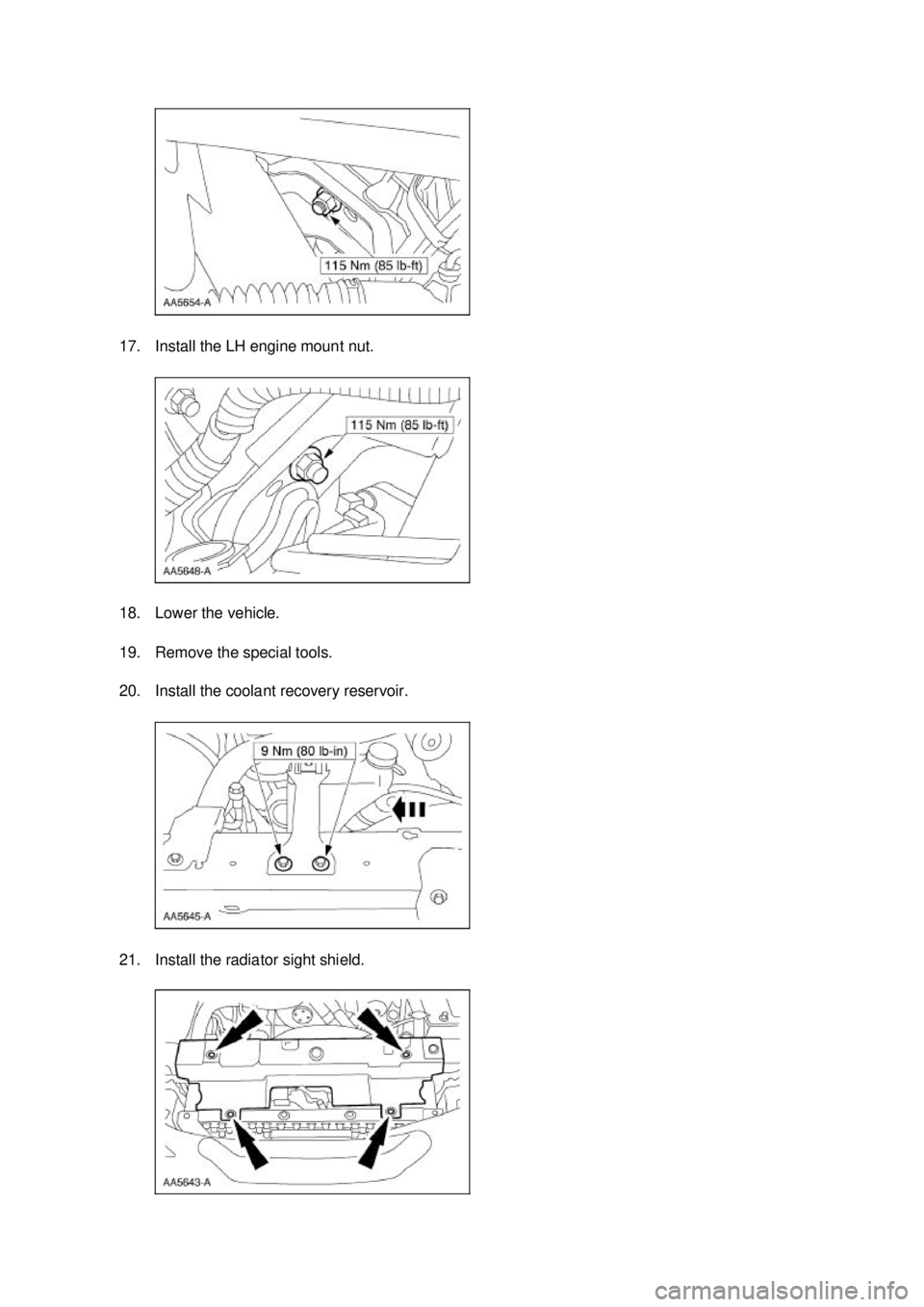
17. Install the LH engine mount nut.
18. Lower the vehicle.
19. Remove the special tools.
20. Install the coolant recovery reservoir.
21. Install the radiator sight shield. �K�l�j . 11 �b�a
122003 Mustang Workshop Manual
17. 11. 2011file:///C:/Ford/2000 - 2004/tsocache/SHEF_4464/S3B~us~en~ ...
Page 1037 of 4378
22. Install the air cleaner outlet pipe. For additional information, refer to
Section 303 - 12 .
23. Connect the battery ground cable. For additional information, refer to Section 414 - 01 .
24. Fill the engine with clean engine oil.
25. CAUTION: Correct coolant bleeding is critical for correct engine cooling.
Fill and bleed the engine cooling system. For additional information, refer to Section 303 - 03A . �K�l�j . 12 �b�a
122003 Mustang Workshop Manual
17. 11. 2011file:///C:/Ford/2000 - 2004/tsocache/SHEF_4464/S3B~us~en~ ...
Page 1047 of 4378
IN-
VEHICLE REPAIR
Engine Support Insulators
Removal 1. Disconnect the battery ground cable (14301). For additional information, refer to Section 414 -
01 .
2. Remove the air cleaner outlet tube (9B659). For additional information, refer to Section 303 - 12 .
3. Remove the radiator sight shield (8C291).
4. Remove the coolant recovery reservoir (8A080). 1. Disconnect the hose.
2. Remove the bolts. 3. Remove the coolant recovery reservoir. SECTION 303-
01A: Engine — 3.8L 2003 Mustang Workshop Manual Special Tool(s)
3 Bar Engine Support Kit
303-
F072 Engine Lift Bracket Set
303-
D095 (D94L-6001- A) or
equivalent �K�l�j . 1 �b�a
82003 Mustang Workshop Manual
17. 11. 2011file:///C:/Ford/2000 - 2004/tsocache/SHEF_4464/S3B~us~en~ ...
. For additional information, refer to Section 303 - 05 .
2. Remove the radiator coolant recovery reservoir (8A080).")


. For additional information, refer to Section 414 -
01 .
2. Remove the air cleaner outlet tube")