Page 3548 of 4378

DIAGNOSIS AND TESTING
Module Configuration
Principles of Operation
Some modules must be programmed as part of the repair procedure. If this procedure is not followed
the module will not function correctly and may set a number of DTCs, including B2477 or P1639, which
indicate that some necessary data has not been programmed into the module.
Modules that need programming should not be exchanged between vehicles. In most cases the
parameter values or settings are unique to that vehicle, and if not set correctly will cause concerns or
faults.
Some programmable parameters, such as belt minder on/off, can be changed from the factory setting
at the customer's request.
WDS will automatically attempt to retrieve the module configuration information from all modules, and
from a backup location in the powertrain control module (PCM) when vehicle ID is carried out. If the
module and the PCM do not contain correct information the diagnostic tool will either request "As Built"
data or display a list of items that you will need to manually configure. The diagnostic tool will program
the module based on the data you enter.
There are three different methods that are used for module programming:
�zprogrammable module installation (PMI)
�z calibration update
�z programmable parameters
Some modules do not support all three methods.
Programmable Module Installation (PMI)
The programmable module installation (PMI) method is used when a new programmable module is
installed on the vehicle. It is no longer necessary to command the diagnostic tool to gather module
option content from the old module. The diagnostic tool automatically obtains any available module
option content information from the old module during the vehicle ID routine that runs when the
diagnostic tool is initially connected to the vehicle. It is important that you connect WDS to the vehicle
and allow it to identify the vehicle and obtain configuration data prior to removing any modules. Calibration Update SECTION 418-
01: Module Configuration 2003 Mustang Workshop Manual Special Tool(s)
Worldwide Diagnostic System
(WDS)
418-
F224
New Generation STAR (NGS)
Tester
418- F052 or equivalent
diagnostic tool �K�l�j . 1 �b�a
32003 Mustang Workshop Manual
18. 11. 2011file:///C:/Ford/2000 - 2004/tsocache/SHEF_5108/S3B~us~en~ ...
Page 3550 of 4378
Programmable Parameters Index
System Programmable Parameter Items
Warnings & Chimes Belt Minder �K�l�j . 3 �b�a
32003 Mustang Workshop Manual
18. 11. 2011file:///C:/Ford/2000 - 2004/tsocache/SHEF_5108/S3B~us~en~ ...
Page 3619 of 4378
SPECIFICATIONS
SECTION 501-
05: Interior Trim and Ornamentation 2003 Mustang Workshop Manual General Specifications
Item Specification
Adhesives
Headliner Adhesive
F1VY-
19562- A WSS-
M2G355- B
Torque Specifications Description Nm lb-
ft Safety belt guide bolt 40 30
Safety belt anchor bolt 40 30
Rear seat backrest bolster bolts 11 8
Rear seat backrest bolts 11 8 �K�l�j . 1 �b�a
12003 Mustang Workshop Manual
18. 11. 2011file:///C:/Ford/2000 - 2004/tsocache/SHEF_5108/S3B~us~en~ ...
Page 3626 of 4378
REMOVAL AND INSTALLATION
Trim Panel —
Quarter, Convertible
Removal and Installation 1. Lower the convertible top to the full down position.
2. Remove the rear seat cushion.
3. Remove the two bolts and the rear seat backrest.
4. Remove the scuff plate.
5. Using the special tool, remove the front safety belt anchor bolt.
SECTION 501-
05: Interior Trim and Ornamentation 2003 Mustang Workshop Manual Special Tool(s)
Safety Belt Bolt Bit
501-
010 (T77L-2100- A) �K�l�j . 1 �b�a
32003 Mustang Workshop Manual
18. 11. 2011file:///C:/Ford/2000 - 2004/tsocache/SHEF_5108/S3B~us~en~ ...
Page 3629 of 4378
REMOVAL AND INSTALLATION
Trim Panel —
Upper Quarter
Removal and Installation 1. Remove the rear seat cushion.
2. Using the special tool, remove the rear safety belt anchor bolt.
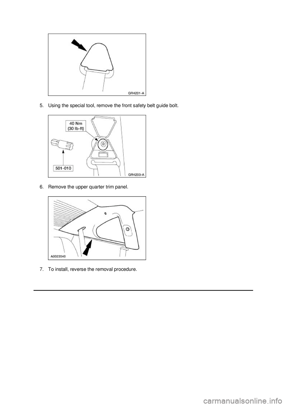
3. Remove the screw and the coat hook. 4. Open the front safety belt guide bolt cover. SECTION 501-
05: Interior Trim and Ornamentation 2003 Mustang Workshop Manual Special Tool(s)
Safety Belt Bolt Bit
501-
010 (T77L-2100- A) �K�l�j . 1 �b�a
32003 Mustang Workshop Manual
18. 11. 2011file:///C:/Ford/2000 - 2004/tsocache/SHEF_5108/S3B~us~en~ ...
Page 3630 of 4378
5. Using the special tool, remove the front safety belt guide bolt.
6. Remove the upper quarter trim panel.
7. To install, reverse the removal procedure. �K�l�j . 2 �b�a
32003 Mustang Workshop Manual
18. 11. 2011file:///C:/Ford/2000 - 2004/tsocache/SHEF_5108/S3B~us~en~ ...
Page 3632 of 4378
REMOVAL AND INSTALLATION
Trim Panel —
Package Tray
Removal and Installation 1. Remove the screw and the coat hook.
2. NOTE: Inspect the shoulder safety belt guide cover for damage. If the shoulder safety belt guide
cover is damaged or the cover does not remain closed, install a new shoulder safety belt guide
cover.
Open the safety belt cover.
3. Using the special tool, remove the front safety belt guide bolt and position the safety belt guide aside.
SECTION 501-
05: Interior Trim and Ornamentation 2003 Mustang Workshop Manual Special Tool(s)
Torx Bit, Safety Belt Bolt
501-
010 (T77L-2100- A) �K�l�j . 1 �b�a
32003 Mustang Workshop Manual
18. 11. 2011file:///C:/Ford/2000 - 2004/tsocache/SHEF_5108/S3B~us~en~ ...
Page 3663 of 4378
SPECIFICATIONS
SECTION 501-
10: Seating 2003 Mustang Workshop Manual Torque Specifications
Description Nm lb-
ft lb-
in Front seat track to floorpan bolts and nuts 35 26 —
Front seat track to cushion bolts 20 15 —
Seat latch bolts 27 20 —
Seat backrest latch bolts 55 41 —
Front seat backrest pivot bolt 23 17 —
Rear seat backrest to body bolt 11 8 —
Safety belt guide screws 4 — 35 �K�l�j . 1 �b�a
12003 Mustang Workshop Manual
18. 11. 2011file:///C:/Ford/2000 - 2004/tsocache/SHEF_5108/S3B~us~en~ ...