Page 2577 of 4378

INSTALLATION
Transmission
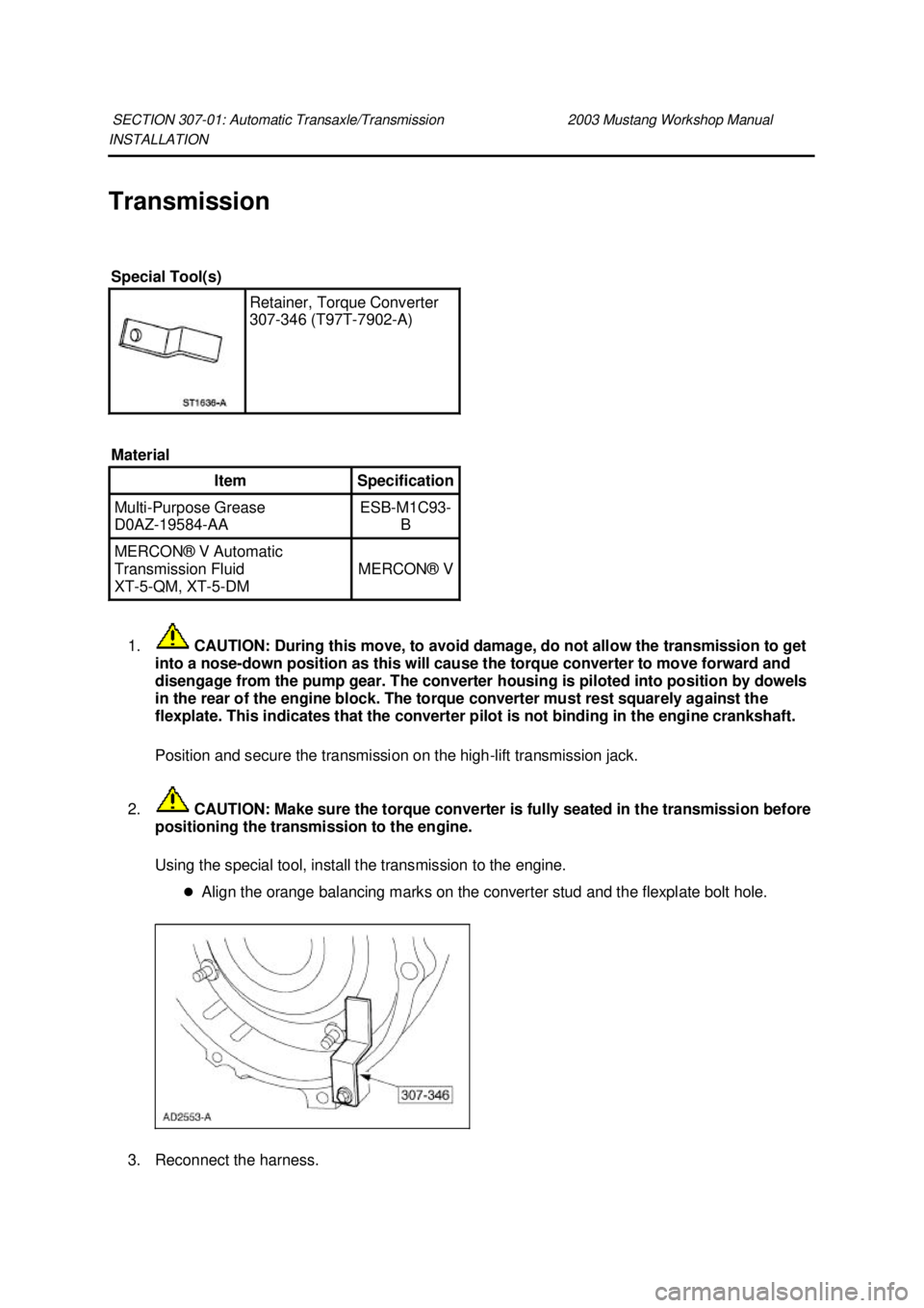
1. CAUTION: During this move, to avoid damage, do not allow the transmission to get
into a nose- down position as this will cause the torque converter to move forward and
disengage from the pump gear. The converter housing is piloted into position by dowels
in the rear of the engine block. The torque converter must rest squarely against the
flexplate. This indicates that the converter pilot is not binding in the engine crankshaft.
Position and secure the transmission on the high- lift transmission jack.
2. CAUTION: Make sure the torque converter is fully seated in the transmission before
positioning the transmission to the engine.
Using the special tool, install the transmission to the engine.
�zAlign the orange balancing marks on the converter stud and the flexplate bolt hole. 3. Reconnect the harness. SECTION 307-
01: Automatic Transaxle/Transmission 2003 Mustang Workshop Manual Special Tool(s)
Retainer, Torque Converter
307-
346 (T97T-7902- A)
Material Item Specification
Multi-
Purpose Grease
D0AZ- 19584- AA ESB-
M1C93-
B MERCON® V Automatic
Transmission Fluid
XT
-5-QM, XT -5-DM MERCON® V �K�l�j . 1 �b�a
72003 Mustang Workshop Manual
18. 11. 2011file:///C:/Ford/2000 - 2004/tsocache/SHEF_2748/S3B~us~en~ ...
Page 2583 of 4378
23.
NOTE: When the battery is disconnected and reconnected, some abnormal drive symptoms
may occur while the vehicle relearns its adaptive strategy. The vehicle may need to be driven
16 km (10 miles) or more until the vehicle relearns the strategy.
Connect the battery ground cable.
24. If required, fill the transmission with clean automatic transmission fluid.
25. Check the transmission for correct operation. �K�l�j . 7 �b�a
72003 Mustang Workshop Manual
18. 11. 2011file:///C:/Ford/2000 - 2004/tsocache/SHEF_2748/S3B~us~en~ ...
Page 2584 of 4378
SPECIFICATIONS
SECTION 307-
02: Transaxle/Transmission Cooling 2003 Mustang Workshop Manual General Specifications
Item Specification
Fluid
MERCON® V Automatic Transmission Fluid XT
-5-QM MERCON® V
Torque Specifications Description Nm lb-
ft Fluid cooler tube nut at radiator 32 24
Cooler line bracket to engine nut 48 35
Fluid cooler tube nut at transmission 21 15 �K�l�j . 1 �b�a
12003 Mustang Workshop Manual
18. 11. 2011file:///C:/Ford/2000 - 2004/tsocache/SHEF_2748/S3B~us~en~ ...
Page 2585 of 4378
DESCRIPTION AND OPERATION
Transmission Cooling —
Integral
This vehicle with an automatic transmission is equipped with an integral transmission fluid cooler. The
cooler is contained inside of the radiator outlet tank and cannot be serviced separately. The cooler
transfers heat from the transmission fluid to the engine coolant.
For transmission fluid cooler flow test, refer to Section 307 - 01 .
For transmmission fluid cooler backflushing and cleaning, refer to Section 307 - 01 .
Transmission Fluid Cooler Tubes SECTION 307-
02: Transaxle/Transmission Cooling 2003 Mustang Workshop Manual Item Part Number Description
1 — Fluid cooler inlet tube
2 — Fluid cooler outlet tube
3 7005 Transmission case
4 — Transmission case fittings �K�l�j . 1 �b�a
22003 Mustang Workshop Manual
18. 11. 2011file:///C:/Ford/2000 - 2004/tsocache/SHEF_2748/S3B~us~en~ ...
Page 2590 of 4378
1.
NOTE: Use a backup wrench to hold the case fitting secure.
Install the fluid cooler tubes at the transmission.
2. Install the fluid cooler tube bracket at the engine.
3. Install the nuts.
4. Lower the vehicle.
5. Connect the battery cables.
6. Fill the transmission with fluid and verify proper operation. �zUse Motorcraft MERCON® V Automatic Transmission Fluid XT -5-QM or equivalent
meeting MERCON® V specification. �K�l�j . 2 �b�a
32003 Mustang Workshop Manual
18. 11. 2011file:///C:/Ford/2000 - 2004/tsocache/SHEF_2748/S3B~us~en~ ...
Page 2592 of 4378
SPECIFICATIONS
SECTION 307-
05: Automatic Transaxle/Transmission External Controls 2003 Mustang Workshop Manual Torque Specifications
Description Nm lb-
ft lb-
in Steering Column Nuts 40 30 —
Shift Interlock Cable 7 — 62
Shift Cable Bracket 12 9 — �K�l�j . 1 �b�a
12003 Mustang Workshop Manual
18. 11. 2011file:///C:/Ford/2000 - 2004/tsocache/SHEF_2748/S3B~us~en~ ...
Page 2593 of 4378

DESCRIPTION AND OPERATION
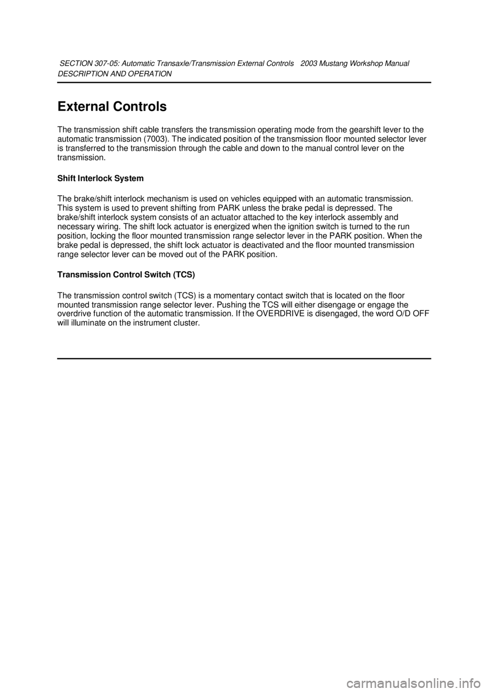
External Controls
The transmission shift cable transfers the transmission operating mode from the gearshift lever to the
automatic transmission (7003). The indicated position of the transmission floor mounted selector lever
is transferred to the transmission through the cable and down to the manual control lever on the
transmission.
Shift Interlock System
The brake/shift interlock mechanism is used on vehicles equipped with an automatic transmission.
This system is used to prevent shifting from PARK unless the brake pedal is depressed. The
brake/shift interlock system consists of an actuator attached to the key interlock assembly and
necessary wiring. The shift lock actuator is energized when the ignition switch is turned to the run
position, locking the floor mounted transmission range selector lever in the PARK position. When the
brake pedal is depressed, the shift lock actuator is deactivated and the floor mounted transmission
range selector lever can be moved out of the PARK position.
Transmission Control Switch (TCS)
The transmission control switch (TCS) is a momentary contact switch that is located on the floor
mounted transmission range selector lever. Pushing the TCS will either disengage or engage the
overdrive function of the automatic transmission. If the OVERDRIVE is disengaged, the word O/D OFF
will illuminate on the instrument cluster.
SECTION 307-
05: Automatic Transaxle/Transmission External Controls 2003 Mustang Workshop Manual �K�l�j . 1 �b�a
12003 Mustang Workshop Manual
18. 11. 2011file:///C:/Ford/2000 - 2004/tsocache/SHEF_2748/S3B~us~en~ ...
Page 2594 of 4378

DIAGNOSIS AND TESTING
External Controls
Refer to Wiring Diagrams Cell
37 , Shift Lock for schematic and connector information.
Refer to Wiring Diagrams Cell 29 , Transmission Control for schematic and connector information.
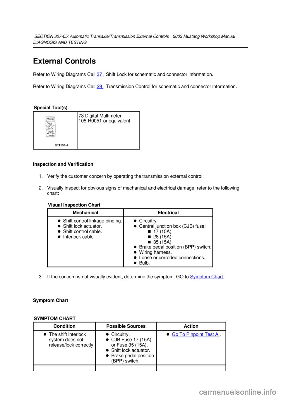
Inspection and Verification 1. Verify the customer concern by operating the transmission external control.
2. Visually inspect for obvious signs of mechanical and electrical damage; refer to the following chart:
3. If the concern is not visually evident, determine the symptom. GO to Symptom Chart .
Symptom Chart SECTION 307-
05: Automatic Transaxle/Transmission External Controls 2003 Mustang Workshop Manual Special Tool(s)
73 Digital Multimeter
105-
R0051 or equivalent
Visual Inspection Chart Mechanical Electrical
�z
Shift control linkage binding.
�z Shift lock actuator.
�z Shift control cable.
�z Interlock cable. �z
Circuitry.
�z Central junction box (CJB) fuse:
�„17 (15A)
�„ 28 (15A)
�„ 35 (15A)
�z Brake pedal position (BPP) switch.
�z Wiring harness.
�z Loose or corroded connections.
�z Bulb.
SYMPTOM CHART Condition
Possible Sources Action
�z The shift interlock
system does not
release/lock correctly �z
Circuitry.
�z CJB Fuse 17 (15A)
or Fuse 35 (15A).
�z Shift lock actuator.
�z Brake pedal position
(BPP) switch. �z
Go To Pinpoint Test A . �K�l�j . 1 �b�a
62003 Mustang Workshop Manual
18. 11. 2011file:///C:/Ford/2000 - 2004/tsocache/SHEF_2748/S3B~us~en~ ...