Page 1828 of 4378
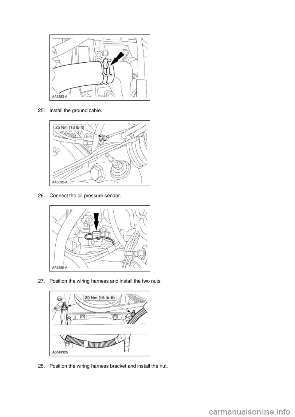
25. Install the ground cable.
26. Connect the oil pressure sender.
27. Position the wiring harness and install the two nuts.
28. Position the wiring harness bracket and install the nut. �K�l�j . 8 �b�a
182003 Mustang Workshop Manual
17. 11. 2011file:///C:/Ford/2000 - 2004/tsocache/SHEF_4464/S3B~us~en~ ...
Page 1834 of 4378
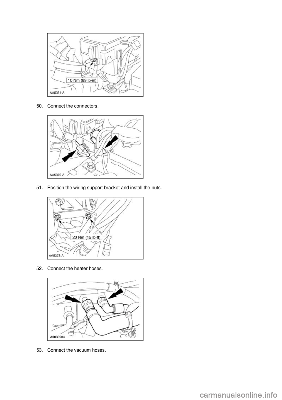
50. Connect the connectors.
51. Position the wiring support bracket and install the nuts.
52. Connect the heater hoses.
53. Connect the vacuum hoses. �K�l�j . 14 �b�a
182003 Mustang Workshop Manual
17. 11. 2011file:///C:/Ford/2000 - 2004/tsocache/SHEF_4464/S3B~us~en~ ...
Page 1835 of 4378
54. Connect the fuel charging wiring harness.
55. Connect the 16-
pin and the 42-pin connectors.
56. Connect the evaporative emissions return tube. 57. Position the cables, and install the bolts. �K�l�j . 15 �b�a
182003 Mustang Workshop Manual
17. 11. 2011file:///C:/Ford/2000 - 2004/tsocache/SHEF_4464/S3B~us~en~ ...
Page 1836 of 4378
58. Connect the throttle cable and the speed control actuator cable, and install the throttle return
spring.
59. Install the upper radiator hose.
60. Connect the wiring connector.
61. Install the air cleaner assembly. 1. Install the air cleaner and the outlet tube as an assembly
2. Install the bolt. �K�l�j . 16 �b�a
182003 Mustang Workshop Manual
17. 11. 2011file:///C:/Ford/2000 - 2004/tsocache/SHEF_4464/S3B~us~en~ ...
Page 1851 of 4378
.
Cap — 4.6L
WARNING: Never remove the pressure relief ca")
pressure reading. Release pressure and repeat the test. Install a new radiator cap if the
pressure is not 99.3-
121.4 kPa (14.4-17.6 psi).
Cap — 4.6L
WARNING: Never remove the pressure relief cap while the engine is operating or when the
cooling system is hot. Failure to follow these instructions can result in damage to the cooling
system or engine or personal injury. To avoid having scalding hot coolant or steam blow out of
the degas bottle when removing the pressure relief cap, wait until the engine is cooled, then
wrap a thick cloth around the pressure relief cap and turn it slowly. Step back while the
pressure is released from the cooling system. When you are sure all the pressure has been
released, turn and remove the pressure relief cap (still with a cloth).
1. Remove the pressure relief cap from the degas bottle.
2. Follow the instructions from the pressure tester.
3. NOTE: If the plunger of the pump is depressed too quickly, an erroneous pressure reading will
result.
Slowly depress the plunger of the pressure test pump until the pressure gauge reading stops
increasing and note the highest pressure reading obtained.
4. If the pressure test gauge readings are not within specifications, install a new pressure relief cap. If the pressure test gauge readings are within specifications, carry out the cooling system
Pressure Test.
Thermostat — Water
A new water thermostat should be installed only after the following electrical and mechanical tests
have been carried out.
Thermostat — Electrical Test
CAUTION: Always vent the exhaust to the outside when carrying out this test.
NOTE: The electrical thermostat test is most accurate if carried out at less than 37.8°C (100°F)
ambient air. This test may be carried out with or without the hood open and with the engine warm or
cold.
1. Check the engine coolant level. Fill as needed.
2. With the ignition OFF, remove the engine coolant temperature (ECT) (4.6L) or cylinder head temperature (CHT) (3.8L) sensor harness connector and attach ECT (4.6L) or CHT (3.8L)
Sensor "T" Cable as a jumper between the powertrain control module (PCM) (12A650) and the
ECT (4.6L) or CHT (3.8L) sensor. Attach the 73III Automotive Meter to the ECT (4.6L) or CHT
(3.8L) Sensor "T" Cable. Voltage values (0- 5 V) may now be monitored while the sensor retains
its connection to the wiring harness.
An appropriate diagnostic tool may be used to monitor the ECT on vehicles equipped with data link connector (DLC). �K�l�j . 8 �b�a
102003 Mustang Workshop Manual
17. 11. 2011file:///C:/Ford/2000 - 2004/tsocache/SHEF_4464/S3B~us~en~ ...
Page 1875 of 4378
REMOVAL AND INSTALLATION
Bypass Tube —
Cobra
Removal and Installation 1. Drain the engine coolant. For additional information, refer to Cooling System Draining, Filling and Bleeding in this section.
2. Disconnect the radiator upper hose and the radiator lower hose.
3. Remove the supercharger belt. For additional information, refer to Section 303 - 05 .
4. Disconnect the engine coolant temperature sensor electrical connector and unclip the wiring harness from the stud.
5. NOTE: LH is shown, RH is similar.
Remove the coolant bypass nuts.
SECTION 303-
03A: Engine Cooling 2003 Mustang Workshop Manual Material
Item Specification
Motorcraft Premium Gold
Engine Coolant
VC
-7-A (in Oregon VC-7- B)
(yellow color) WSS-
M97B51-
A1 �K�l�j . 1 �b�a
22003 Mustang Workshop Manual
18. 11. 2011file:///C:/Ford/2000 - 2004/tsocache/SHEF_4464/S3B~us~en~ ...
Page 1901 of 4378
 or equivalent meeting Ford specification
ESE- M97B44- A (green c")
CAUTION: Some vehicle cooling systems are filled with Motorcraft Premium Engine
Coolant VC -4-A (in Oregon VC- 5, in Canada CXC- 10) or equivalent meeting Ford specification
ESE- M97B44- A (green color). Others are filled with Motorcraft Premium Gold Engine Coolant
VC -7-A or equivalent meeting Ford specification WSS- M97B51-A1 (yellow color). Always fill the
cooling system with the same coolant that is present in the system. Do not mix coolant types.
NOTE: The addition of Motorcraft Cooling System Stop Leak Pellets, VC- 6, darkens Motorcraft
Premium Gold Engine Coolant from yellow to golden tan.
1. Verify the customer's concern by operating the engine to duplicate the condition.
2. Inspect to determine if any of the following mechanical or electrical concerns apply.
3. If the inspection reveals an obvious concern that can be readily identified, repair it as necessary.
4. Inspect the coolant condition. 1. WARNING: Never remove the pressure relief cap while the engine is
operating or when the cooling system is hot. Failure to follow these instructions
can result in damage to the cooling system or engine or personal injury. To avoid
having scalding hot coolant or steam blow out of the degas bottle when removing
the pressure relief cap, wait until the engine has cooled, then wrap a thick cloth
around the pressure relief cap and turn it slowly. Step back while the pressure is
released from the cooling system. When you are sure all the pressure has been
released, (still with a cloth) turn and remove the pressure relief cap.
Allow the engine to cool. Once pressure is released, remove the pressure relief cap.
2. CAUTION: Check the coolant and engine oil level and top off the coolant if
needed. If there is engine coolant in the engine oil the cause must be corrected
and oil/fluid changed or major component damage can occur.
CAUTION: Some vehicle cooling systems are filled with Motorcraft Premium
Engine Coolant VC -4-A (in Oregon VC- 5, in Canada CXC- 10) or equivalent meeting
Ford specification ESE- M97B44-A (green color). Others are filled with Motorcraft
Premium Gold Engine Coolant VC -7-A or equivalent meeting Ford specification
WSS- M97B51- A1 (yellow color). Always fill the cooling system with the same
coolant that is present in the system. Do not mix coolant types.
Inspect the coolant color:
�„If Motorcraft Premium Engine Coolant (green color) VC-4- A or equivalent meeting
Ford specification ESE-M97B44- A has a clear, light green or blue color, this Visual Inspection Chart
Mechanical Electrical
�z
Radiator brackets
�z Leaks
�z Damaged hoses
�z Hose clamps
�z Water pump
�z Radiator
�z Degas bottle
�z Water pump bracket �z
Damaged water pump wiring �K�l�j . 2 �b�a
72003 Mustang Workshop Manual
18. 11. 2011file:///C:/Ford/2000 - 2004/tsocache/SHEF_4464/S3B~us~en~ ...
Page 1926 of 4378

REMOVAL AND INSTALLATION
Fuel Charging Wiring Harness
Removal and Installation
WARNING: Do not smoke or carry lighted tobacco or open flame of any type when
working on or near any fuel related components. Highly flammable mixtures are always present
and may ignite. Failure to follow these instructions may result in personal injury.
1. Disconnect the battery ground cable. For additional information, refer to Section 414 - 01 .
2. Remove the upper intake manifold. For additional information, refer to Section 303 - 01A .
3. Disconnect the following electrical connectors. �z42- pin engine bulkhead connector
�z 16- pin connector
�z 8-pin connector
�z A/C pressure switch
4. Separate the wiring harness from the dash panel.
5. Disconnect the intake manifold runner control (IMRC) actuator electrical connector.
SECTION 303-
04A: Fuel Charging and Controls — 3.8L 2003 Mustang Workshop Manual �K�l�j . 1 �b�a
42003 Mustang Workshop Manual
18. 11. 2011file:///C:/Ford/2000 - 2004/tsocache/SHEF_4464/S3B~us~en~ ...