Page 159 of 256

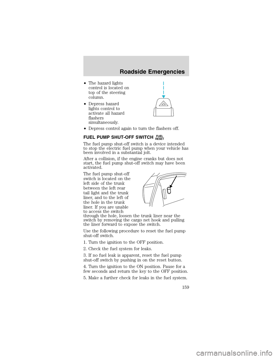
•The hazard lights
control is located on
top of the steering
column.
•Depress hazard
lights control to
activate all hazard
flashers
simultaneously.
•Depress control again to turn the flashers off.
FUEL PUMP SHUT-OFF SWITCH
FUEL
RESET
The fuel pump shut-off switch is a device intended
to stop the electric fuel pump when your vehicle has
been involved in a substantial jolt.
After a collision, if the engine cranks but does not
start, the fuel pump shut-off switch may have been
activated.
The fuel pump shut-off
switch is located on the
left side of the trunk
between the left rear
tail light and the trunk
liner, and to the left of
the hole in the trunk
liner. If you are unable
to access the switch
through the hole, loosen the trunk liner near the
switch by removing the cargo net hook and pulling
the liner forward to expose the switch.
Use the following procedure to reset the fuel pump
shut-off switch.
1. Turn the ignition to the OFF position.
2. Check the fuel system for leaks.
3. If no fuel leak is apparent, reset the fuel pump
shut-off switch by pushing in on the reset button.
4. Turn the ignition to the ON position. Pause for a
few seconds and return the key to the OFF position.
5. Make a further check for leaks in the fuel system.
Roadside Emergencies
159
Page 161 of 256
To remove a fuse use the fuse puller tool provided
on the fuse panel cover.
The fuses are coded as follows:
Fuse/Relay
LocationFuse Amp
RatingPassenger Compartment Fuse
Panel Description
1 20A Cigar lighter
2 20A Engine controls
3—Not used
4 10A Right-hand low beam headlamp
5 15A Instrument cluster, Traction
control switch
6 20A Starter motor relay
7 15A GEM, Interior lamps
8 20A Engine controls
9 30A Mach 460 subwoofers
10 10A Left—hand low beam headlamp
11 15A Back-up lamps
12—Not used
13 15A Electronic flasher
14—Not used
15 15A Power lumbar
SEE OWNERS MANUAL FOR FUSE INFO
4212345
76891011
131214151617
191820212223
252426272829
313032333435
373638394041
43
44
Roadside Emergencies
161
Page 162 of 256

Fuse/Relay
LocationFuse Amp
RatingPassenger Compartment Fuse
Panel Description
16—Not used
17 15A Speed control servo, Shift lock
actuator
18 15A Electronic flasher
19 15A Power mirror switch, GEM,
Anti-theft relay, Power door
locks, Door ajar switches
20 15A Convertible top switch
21 5A Instrument cluster and engine
control memory
22—Not used
23 15A A/C clutch, Defogger switch
24 30A Climate control blower motor
25 25A Luggage compartment lid release
26 30A Wiper/Washer motor, Wiper
relays
27 20A Radio
28 15A GEM, Overdrive cancel switch
29 15A Anti-lock Brake System (ABS)
module
30 15A Daytime Running Lamps (DRL)
module
31 10A Data link connector
32 15A Radio, GEM
33 15A Stop lamp switch, Speed control
deactivation switch
34 20A Instrument Cluster, CCRM, Data
link connector, Securilock
transceiver module
35 15A Shift lock actuator, Powertrain
Control Module (PCM), Speed
control servo, ABS module
36 15A Air bag control module
37 5A Adjustable illumination
38 20A High beams
39 5A GEM
40—Not used
Roadside Emergencies
162
Page 163 of 256
Fuse/Relay
LocationFuse Amp
RatingPassenger Compartment Fuse
Panel Description
41 15A Brake lamp
42—Not used
43 20A CB Power windows
44—Not used
Power distribution box
The power distribution box is located in the engine
compartment. The power distribution box contains
high-current fuses that protect your vehicle’s main
electrical systems from overloads.
Always disconnect the battery before
servicing high current fuses.
Always replace the cover to the power
distribution box before reconnecting the
battery or refilling fluid reservoirs
If the battery has been disconnected and
reconnected, refer to theBatterysection of the
Maintenance and specificationschapter.
5
RELAY4
RELAY3
RELAY2
RELAY1
RELAY
12
MAXI
29
DIODE28
CB27
MAXI26
MAXI25
MAXI23
MINI
24
MINI
21
MINI
22
MINI
19
MINI17
MINI18
MINI15
MINI13
MINI
14
MINI16
MINI20
MINI
11
MAXI10
MAXI9
MAXI8
MAXI7
MAXI6
MAXI5
MAXI4
MAXI3
MAXI2
MAXI1
MAXI
SEE OWNERS MANUAL CONSULTER LA GUIDE
Roadside Emergencies
163
Page 167 of 256
If the vehicle slips off the jack, you or
someone else could be seriously injured.
1. Park on a level
surface, activate hazard
flashers and set
parking brake.
2. Place gearshift lever
in P (Park) or R (manual transmission), turn engine
OFF, and block the diagonally opposite wheel.
3. Remove the spare
tire, jack and lug
wrench.
4. Remove the center
ornament (if equipped)
from the wheel. Loosen
each wheel lug nut
one-half turn
counterclockwise but
do not remove them
until the wheel is
raised off the ground.
Roadside Emergencies
167
Page 168 of 256
5. Put the jack in the
jack notch next to the
tire you are changing.
Turn the jack handle
clockwise until the
wheel is completely off
the ground.
Never use the rear
differential as a
jacking point.
To lessen the
risk of personal
injury, do not put any
part of your body
under the vehicle
while changing a tire.
Do not start the
engine when your
vehicle is on the jack.
The jack is only
meant for changing
the tire.
6. Remove the lug nuts with the lug wrench.
7. Replace the flat tire with the spare tire, making
sure the valve stem is facing outward. Reinstall lug
nuts until the wheel is snug against the hub. Do not
fully tighten the lug nuts until the wheel has been
lowered.
If you are using the temporary tire, the lug nut
washers will not appear to be flush with the rim.
This is normal only when using the temporary spare
tire.
8. Lower the wheel by turning the jack handle
counterclockwise.
Roadside Emergencies
168
Page 170 of 256

3. Install the lug nut by turning the wrench
clockwise.
JUMP STARTING YOUR VEHICLE
The gases around the battery can explode if
exposed to flames, sparks, or lit cigarettes.
An explosion could result in injury or vehicle
damage.
Batteries contain sulfuric acid which can
burn skin, eyes and clothing, if contacted.
Do not attempt to push-start your vehicle.
Automatic transmissions do not have
push-start capability; also, the catalytic
converter may become damaged.
Preparing your vehicle
When the battery is disconnected or a new battery is
installed, the transmission must relearn its shift
strategy. As a result, the transmission may have firm
and/or soft shifts. This operation is considered
normal and will not affect function or durability of
the transmission. Over time, the adaptive learning
process will fully update transmission operation.
1.Use only a 12–volt supply to start your
vehicle.
2. Do not disconnect the battery of the disabled
vehicle as this could damage the vehicle’s electrical
system.
3. Park the booster vehicle close to the hood of the
disabled vehicle making sure the two vehiclesdo
nottouch. Set the parking brake on both vehicles
and stay clear of the engine cooling fan and other
moving parts.
4. Check all battery terminals and remove any
excessive corrosion before you attach the battery
cables. Ensure the vent caps are tight and level.
5. Turn the heater fan on in both vehicles to protect
any electrical surges. Turn all other accessories off.
Roadside Emergencies
170
Page 172 of 256
4. Make the final connection of the negative (-)
cable to an exposed metal part of the stalled
vehicle’s engine, away from the battery and the
carburetor/fuel injection system.Do notuse fuel
lines, engine rocker covers or the intake manifold as
groundingpoints.
Do not connect the end of the second cable
to the negative (-) terminal of the battery to
be jumped. A spark may cause an explosion of the
gases that surround the battery.
5. Ensure that the cables are clear of fan blades,
belts, moving parts of both engines, or any fuel
delivery system parts.
Jump starting
1. Start the engine of the booster vehicle and run
the engine at moderately increased speed.
2. Start the engine of the disabled vehicle.
3. Once the disabled vehicle has been started, run
both engines for an additional three minutes before
disconnecting the jumper cables.
+–+–
Roadside Emergencies
172