2003 DODGE RAM 5v circuit
[x] Cancel search: 5v circuitPage 246 of 2895
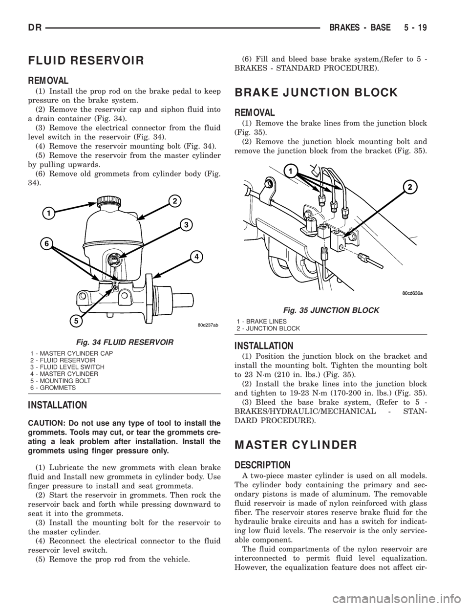
FLUID RESERVOIR
REMOVAL
(1) Install the prop rod on the brake pedal to keep
pressure on the brake system.
(2) Remove the reservoir cap and siphon fluid into
a drain container (Fig. 34).
(3) Remove the electrical connector from the fluid
level switch in the reservoir (Fig. 34).
(4) Remove the reservoir mounting bolt (Fig. 34).
(5) Remove the reservoir from the master cylinder
by pulling upwards.
(6) Remove old grommets from cylinder body (Fig.
34).
INSTALLATION
CAUTION: Do not use any type of tool to install the
grommets. Tools may cut, or tear the grommets cre-
ating a leak problem after installation. Install the
grommets using finger pressure only.
(1) Lubricate the new grommets with clean brake
fluid and Install new grommets in cylinder body. Use
finger pressure to install and seat grommets.
(2) Start the reservoir in grommets. Then rock the
reservoir back and forth while pressing downward to
seat it into the grommets.
(3) Install the mounting bolt for the reservoir to
the master cylinder.
(4) Reconnect the electrical connector to the fluid
reservoir level switch.
(5) Remove the prop rod from the vehicle.(6) Fill and bleed base brake system,(Refer to 5 -
BRAKES - STANDARD PROCEDURE).
BRAKE JUNCTION BLOCK
REMOVAL
(1) Remove the brake lines from the junction block
(Fig. 35).
(2) Remove the junction block mounting bolt and
remove the junction block from the bracket (Fig. 35).
INSTALLATION
(1) Position the junction block on the bracket and
install the mounting bolt. Tighten the mounting bolt
to 23 N´m (210 in. lbs.) (Fig. 35).
(2) Install the brake lines into the junction block
and tighten to 19-23 N´m (170-200 in. lbs.) (Fig. 35).
(3) Bleed the base brake system, (Refer to 5 -
BRAKES/HYDRAULIC/MECHANICAL - STAN-
DARD PROCEDURE).
MASTER CYLINDER
DESCRIPTION
A two-piece master cylinder is used on all models.
The cylinder body containing the primary and sec-
ondary pistons is made of aluminum. The removable
fluid reservoir is made of nylon reinforced with glass
fiber. The reservoir stores reserve brake fluid for the
hydraulic brake circuits and has a switch for indicat-
ing low fluid levels. The reservoir is the only service-
able component.
The fluid compartments of the nylon reservoir are
interconnected to permit fluid level equalization.
However, the equalization feature does not affect cir-
Fig. 34 FLUID RESERVOIR
1 - MASTER CYLINDER CAP
2 - FLUID RESERVOIR
3 - FLUID LEVEL SWITCH
4 - MASTER CYLINDER
5 - MOUNTING BOLT
6 - GROMMETS
Fig. 35 JUNCTION BLOCK
1 - BRAKE LINES
2 - JUNCTION BLOCK
DRBRAKES - BASE 5 - 19
Page 257 of 2895
(6) Install the rotor (Refer to 5 - BRAKES/HY-
DRAULIC/MECHANICAL/ROTORS - INSTALLA-
TION).
(7) Install the caliper adapter (Refer to 5 -
BRAKES/HYDRAULIC/MECHANICAL/DISC
BRAKE CALIPER ADAPTER - INSTALLATION).
(8) Install the caliper (Refer to 5 - BRAKES/HY-
DRAULIC/MECHANICAL/DISC BRAKE CALIPERS
- INSTALLATION).
(9) Install the wheel and tire assembly (Refer to 22
- TIRES/WHEELS/WHEELS - STANDARD PROCE-
DURE).
PARKING BRAKE
DESCRIPTION
The parking brakes are operated by a system of
cables and levers attached to a primary and second-
ary shoe positioned within the drum section of the
rotor.
The drum-in-hat design utilizes an independent set
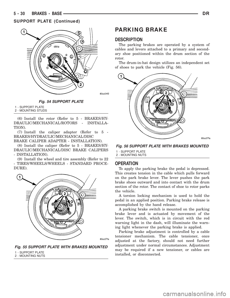
of shoes to park the vehicle (Fig. 56).
OPERATION
To apply the parking brake the pedal is depressed.
This creates tension in the cable which pulls forward
on the park brake lever. The lever pushes the park
brake shoes outward and into contact with the drum
section of the rotor. The contact of shoe to rotor parks
the vehicle.
A torsion locking mechanism is used to hold the
pedal in an applied position. Parking brake release is
accomplished by the hand release.
A parking brake switch is mounted on the parking
brake lever and is actuated by movement of the
lever. The switch, which is in circuit with the red
warning light in the dash, will illuminate the warn-
ing light whenever the parking brake is applied.
Parking brake adjustment is controlled by a cable
tensioner mechanism. The cable tensioner, once
adjusted at the factory, should not need further
adjustment under normal circumstances. Adjustment
may be required if a new tensioner, or cables are
installed, or disconnected.
Fig. 54 SUPPORT PLATE
1 - SUPPORT PLATE
2 - MOUNTING STUDS
Fig. 55 SUPPORT PLATE WITH BRAKES MOUNTED
1 - SUPPORT PLATE
2 - MOUNTING NUTS
Fig. 56 SUPPORT PLATE WITH BRAKES MOUNTED
1 - SUPPORT PLATE
2 - MOUNTING NUTS
5 - 30 BRAKES - BASEDR
SUPPORT PLATE (Continued)
Page 266 of 2895

BRAKES - ABS
TABLE OF CONTENTS
page page
BRAKES - ABS
DESCRIPTION.........................39
OPERATION...........................39
STANDARD PROCEDURE - ABS BRAKE
BLEEDING...........................40
SPECIFICATIONS
TORQUE CHART......................40
FRONT WHEEL SPEED SENSOR
DESCRIPTION.........................41
OPERATION...........................41
REMOVAL.............................41
INSTALLATION.........................42
REAR WHEEL SPEED SENSOR
DIAGNOSIS AND TESTING - REAR WHEEL
ANTILOCK...........................42
REMOVAL.............................42
INSTALLATION.........................43
TONE WHEEL
DIAGNOSIS AND TESTING - REAR WHEEL
SPEED SENSOR......................43HYDRAULIC/MECHANICAL
DESCRIPTION - ELECTRONIC VARIABLE
BRAKE PROPORTIONING...............43
OPERATION - ELECTRONIC VARIABLE
BRAKE PROPORTIONING...............43
HCU (HYDRAULIC CONTROL UNIT)
DESCRIPTION.........................43
OPERATION...........................43
REMOVAL.............................44
INSTALLATION.........................44
R WA L VA LV E
DESCRIPTION.........................44
OPERATION...........................44
REMOVAL.............................45
INSTALLATION.........................45
BRAKES - ABS
DESCRIPTION
The antilock brake system (ABS) is an electroni-
cally operated, three channel brake control system.
The vehicle has Electronic Variable Brake Propor-
tioning (EVBP) designed into the system which elim-
inates the combination/proportioning valve.
The system is designed to prevent wheel lockup
and maintain steering control during braking. Pre-
venting lockup is accomplished by modulating fluid
pressure to the wheel brake units.
The hydraulic system is a three channel design.
The front wheel brakes are controlled individually
and the rear wheel brakes in tandem. The ABS elec-
trical system is separate from other electrical circuits
in the vehicle. A specially programmed controller
antilock brake unit operates the system components.
ABS system major components include:
²Controller Antilock Brakes (CAB)
²Hydraulic Control Unit (HCU)
²Wheel Speed Sensors (WSS)
²ABS Warning Light
OPERATION
Battery voltage is supplied to the CAB. The CAB
performs a system initialization procedure at start
up. A check of the ABS motor is performed at 15
miles per hour. Initialization consists of a static and
dynamic self check of system electrical components.
The static and dynamic checks occurs at ignition
start up. During the dynamic check, the CAB briefly
cycles solenoids to verify operation. An audible noise
may be heard during this self check. This noise
should be considered normal. The ABS motor and
pump are then checked at a speed of 15 mile per
hour.
If an ABS component exhibits a fault during ini-
tialization, the CAB illuminates the amber warning
light and registers a fault code in the microprocessor
memory.
The CAB monitors wheel speed sensor inputs con-
tinuously while the vehicle is in motion. However,
the CAB will not activate any ABS components as
long as sensor inputs indicate normal braking.
During normal braking, the master cylinder, power
booster and wheel brake units all function as they
would in a vehicle without ABS. The HCU compo-
nents are not activated.
DRBRAKES - ABS 5 - 39
Page 268 of 2895

DESCRIPTION N´m Ft. Lbs. In. Lbs.
RWAL Valve
Brake Line Fittings19 Ð 170
Rear Wheel Speed Sensor
Mounting Bolt24 Ð 200
FRONT WHEEL SPEED
SENSOR
DESCRIPTION
The ABS brake system uses 3 wheel speed sensors.
A sensor is mounted to each front hub/bearings. The
third sensor is mounted on top of the rear axle dif-
ferential housing.
OPERATION
The Wheel Speed Sensor consists of a magnet sur-
rounded by windings from a single strand of wire.
The sensor sends a small AC signal to the CAB. This
signal is generated by magnetic induction. The mag-
netic induction is created when a toothed sensor ring
(exciter ring or tone wheel) passes the stationary
magnetic WSS.
When the ring gear is rotated, the exciter ring
passes the tip of the WSS. As the exciter ring tooth
approaches the tip of the WSS, the magnetic lines of
force expand, causing the magnetic field to cut across
the sensor's windings. This, in turn causes current to
flow through the WSS circuit (Fig. 1) in one direc-
tion. When the exciter ring tooth moves away from
the sensor tip, the magnetic lines of force collapse
cutting the winding in the opposite direction. This
causes the current to flow in the opposite direction.
Every time a tooth of the exciter ring passes the tip
of the WSS, an AC signal is generated. Each AC sig-
nal (positive to negative signal or sinewave) is inter-
preted by the CAB. It then compares the frequency of
the sinewave to a time value to calculate vehicle
speed. The CAB continues to monitor the frequency
to determine a deceleration rate that would indicate
a possible wheel-locking tendency.
The signal strength of any magnetic induction sen-
sor is directly affected by:
²Magnetic field strength; the stronger the mag-
netic field, the stronger the signal
²Number of windings in the sensor; more wind-
ings provide a stronger signal
²Exciter ring speed; the faster the exciter ring/
tone wheel rotates, the stronger the signal will be
²Distance between the exciter ring teeth and
WSS; the closer the WSS is to the exciter ring/tone
wheel, the stronger the signal will be
The rear WSS is not adjustable. A clearance speci-
fication has been established for manufacturing toler-ances. If the clearance is not within these
specifications, then either the WSS or other compo-
nents may be damaged. The clearance between the
WSS and the exciter ring is 0.005 ± 0.050 in.
The assembly plant performs a ªRolls Testº on
every vehicle that leaves the assembly plant. One of
the test performed is a test of the WSS. To properly
test the sensor, the assembly plant connects test
equipment to the Data Link Connector (DLC). This
connector is located to the right of the steering col-
umn and attached to the lower portion of the instru-
ment panel (Fig. 2). The rolls test terminal is spliced
to the WSS circuit. The vehicle is then driven on a
set of rollers and the WSS output is monitored for
proper operation.
REMOVAL
(1) Remove the front rotor (Refer to 5 - BRAKES/
HYDRAULIC/MECHANICAL/ROTORS - REMOV-
AL).
(2) Remove the wheel speed sensor mounting bolt
from the hub. (Fig. 3)
Fig. 1 Operation of the Wheel Speed Sensor
1 - MAGNETIC CORE
2 - CAB
3 - AIR GAP
4 - EXCITER RING
5 - COIL
DRBRAKES - ABS 5 - 41
BRAKES - ABS (Continued)
Page 269 of 2895

(3) Remove the wheel speed sensor from the hub.
(4) Remove the wiring from the clips and discon-
nect the electrical connector.
INSTALLATION
(1) Install the wiring to the clips and Reconnect
the electrical connector.
(2) Install the wheel speed sensor to the hub.
(3) Install the wheel speed sensor mounting bolt to
the hub. Tighten the bolt to 21 N´m (190 in. lbs.).
(4) Install the front rotor and brake caliper assem-
bly (Refer to 5 - BRAKES/HYDRAULIC/MECHANI-
CAL/ROTORS - INSTALLATION).
REAR WHEEL SPEED SENSOR
DIAGNOSIS AND TESTING - REAR WHEEL
ANTILOCK
Diagnosis of base brake conditions which are
mechanical in nature should be performed first. This
includes brake noise, lack of power assist, parking
brake, or vehicle vibration during normal braking.
The RWAL brake system performs several self-
tests every time the ignition switch is turned on and
the vehicle is driven. The CAB monitors the system
inputs and outputs circuits to verify the system is
operating properly. If the CAB senses a malfunction
in the system it will set a DTC into memory and trig-
ger the warning lamp.
NOTE: The MDS or DRB III scan tool is used to
diagnose the RWAL system. For test procedures
refer to the Chassis Diagnostic Manual.
REMOVAL
(1) Raise the vehicle on a hoist.
(2) Remove the brake line mounting nut and
remove the brake line from the sensor stud.
(3) Remove the mounting stud from the sensor and
shield (Fig. 4).
(4) Remove the sensor and shield from the differ-
ential housing.
(5) Disconnect the sensor wire harness and remove
the sensor.
Fig. 2 Data Link Connector - Typical
1 - 16±WAY DATA LINK CONNECTOR
Fig. 3 WHEEL SPEED SENSOR
1 - WHEEL SPEED SENSOR MOUNTING BOLT
2 - WHEEL SPEED SENSOR
3 - HUB/BEARING
Fig. 4 REAR WHEEL SPEED SENSOR
1 - WHEEL SPEED SENSOR
2 - MOUNTING BOLT
3 - AXLE HOUSING
5 - 42 BRAKES - ABSDR
FRONT WHEEL SPEED SENSOR (Continued)
Page 270 of 2895

INSTALLATION
(1) Connect the harness to the sensor.Be sure
the seal is securely in place between the sensor
and the wiring connector.
(2) Install the O-ring on the sensor (if removed).
(3) Insert the sensor in the differential housing.
(4) Install the sensor shield.
(5) Install the sensor mounting stud and tighten to
24 N´m (200 in. lbs.).
(6) Install the brake line on the sensor stud and
install the nut.
(7) Lower the vehicle.
TONE WHEEL
DIAGNOSIS AND TESTING - REAR WHEEL
SPEED SENSOR
Diagnosis of base brake conditions which are
mechanical in nature should be performed first. This
includes brake noise, lack of power assist, parking
brake, or vehicle vibration during normal braking.
The Antilock brake system performs several self-
tests every time the ignition switch is turned on and
the vehicle is driven. The CAB monitors the system
inputs and outputs circuits to verify the system is
operating properly. If the CAB senses a malfunction
in the system it will set a DTC into memory and trig-
ger the warning lamp.
NOTE: The MDS or DRB III scan tool is used to
diagnose the Antilock Brake system. For test proce-
dures refer to the Chassis Diagnostic Manual.
HYDRAULIC/MECHANICAL
DESCRIPTION - ELECTRONIC VARIABLE
BRAKE PROPORTIONING
Vehicles equipped with ABS use electronic variable
brake proportioning (EVBP) to balance front-to-rear
braking. The EVBP is used in place of a rear propor-
tioning valve. The EVBP system uses the ABS sys-
tem to control the slip of the rear wheels in partial
braking range. The braking force of the rear wheels
is controlled electronically by using the inlet and out-
let valves located in the integrated control unit
(ICU).
OPERATION - ELECTRONIC VARIABLE BRAKE
PROPORTIONING
EVBP is able to decrease, hold and increase rear
brake pressure without activating full ABS control.
Upon entry into EVBP the inlet valve for the rear
brake circuit is switched on so that the fluid supplyfrom the master cylinder is shut off. In order to
decrease the rear brake pressure, the outlet valve for
the rear brake circuit is pulsed. This allows fluid to
enter the low pressure accumulator (LPA) in the
hydraulic control unit (HCU) resulting in a drop in
fluid pressure to the rear brakes. In order to increase
the rear brake pressure, the outlet valve is switched
off and the inlet valve is pulsed. This increases the
pressure to the rear brakes.
The EVBP will remain functional during many
ABS fault modes. If both the red BRAKE and amber
ABS warning indicators are illuminated, the EVBP
may not be functioning.
HCU (HYDRAULIC CONTROL
UNIT)
DESCRIPTION
The HCU consists of a valve body, pump motor, low
pressure accumulators, inlet valves, outlet valves and
noise attenuators.
OPERATION
Accumulators in the valve body store extra fluid
released to the system for ABS mode operation. The
pump provides the fluid volume needed and is oper-
ated by a DC type motor. The motor is controlled by
the CAB.
The valves modulate brake pressure during
antilock braking and are controlled by the CAB.
The HCU provides three channel pressure control
to the front and rear brakes. One channel controls
the rear wheel brakes in tandem. The two remaining
channels control the front wheel brakes individually.
During antilock braking, the solenoid valves are
opened and closed as needed.
During normal braking, the HCU solenoid valves
and pump are not activated. The master cylinder and
power booster operate the same as a vehicle without
an ABS brake system.
NOTE: The three modes mentioned below do occur
but not necessarily in the order listed everytime.
During antilock braking, solenoid valve pressure
modulation occurs in three stages, pressure increase,
pressure hold, and pressure decrease. The valves are
all contained in the valve body portion of the HCU.
PRESSURE DECREASE
The outlet valve is opened and the inlet valve is
closed during the pressure decrease cycle.
A pressure decrease cycle is initiated when speed
sensor signals indicate high wheel slip at one or
more wheels. At this point, the CAB closes the inlet
DRBRAKES - ABS 5 - 43
REAR WHEEL SPEED SENSOR (Continued)
Page 271 of 2895

then opens the outlet valve, which also opens the
return circuit to the accumulators. Fluid pressure is
allowed to bleed off (decrease) as needed to prevent
wheel lock.
Once the period of high wheel slip has ended, the
CAB closes the outlet valve and begins a pressure
increase or hold cycle as needed.
PRESSURE HOLD
Both solenoid valves are closed in the pressure
hold cycle but only the inlet valve is energized. Fluid
apply pressure in the control channel is maintained
at a constant rate. The CAB maintains the hold cycle
until sensor inputs indicate a pressure change is nec-
essary.
PRESSURE INCREASE
The inlet valve is open and the outlet valve is
closed during the pressure increase cycle. The pres-
sure increase cycle is used to reapply thew brakes.
This cycle controls re-application of fluid apply pres-
sure.
REMOVAL
(1) Install a prop rod on the brake pedal to keep
pressure on the brake system.
(2) Disconnect the battery cables from the battery.
(3) Remove the battery.
(4) Disconnect the two electrical harness connec-
tors (Fig. 5).
(5) Remove the five brake lines from the HCU
(Fig. 5).
(6) Remove HCU/CAB mounting bolts and remove
the HCU/CAB (Fig. 5).
INSTALLATION
NOTE: If the CAB is being replaced with a new CAB
is must be reprogrammed with the use of a DRB III.
(1) Install HCU/CAB on the mounts and Tighten
the bolts to 15N´m (11 ft. lbs.) (Fig. 5).
(2) Install the five brake lines to the HCU and
tighten to 19 N´m (170 in. lbs.) (Fig. 5).
(3) Install the two electrical harness connectors to
the HCU/CAB and push down on the release to
secure the connectors.
(4) Install the battery.
(5) Install the battery cables to the battery.
(6) Remove the prop rod on the brake pedal.
(7) Bleed ABS brake system (Refer to 5 - BRAKES
- STANDARD PROCEDURE).
RWAL VALVE
DESCRIPTION
Rear Wheel Antilock (RWAL) brake system is stan-
dard equipment on 1500 series vehicles. The RWAL
brake system is designed to prevent rear wheel
lock-up on virtually all types of road surfaces. RWAL
braking is desirable because a vehicle which is
stopped without locking the rear wheels will retain
directional stability. This allows the driver to retain
greater control of the vehicle during braking.
The valve is located on the drivers side inner
fender under the hood. The valve modulates hydrau-
lic pressure to the rear brakes.
The RWAL components include:
²RWAL Valve
²Controller Antilock brake (CAB)
²Rear Wheel Speed Sensor (WSS)
OPERATION
When the brakes are applied, hydraulic fluid is
routed from the master cylinder's secondary circuit to
the RWAL valve. From there hydraulic fluid is routed
to the rear brakes. The Controller Antilock Brake
(CAB) contains an Electronic Variable Brake Propor-
tioning (EVBP) control algorithm, which proportions
the applied braking force to the rear wheels during
braking. The EVBP function of the RWAL system
takes the place of a conventional hydraulic propor-
tioning valve. The CAB monitors the rear wheel
speed through the rear wheel speed sensor and cal-
culates an estimated vehicle deceleration. When an
established deceleration threshold is exceeded, an
isolation valve is closed to hold the applied brake
pressure to the rear brakes constant. Upon further
increases in the estimated vehicle deceleration, the
isolation valve is selectively opened to increase rear
Fig. 5 HYDRAULIC CONTROL UNIT
1 - HYDRAULIC CONTROL UNIT
2 - MOUNTING BOLTS
5 - 44 BRAKES - ABSDR
HCU (HYDRAULIC CONTROL UNIT) (Continued)
Page 289 of 2895

DESCRIPTIONÐCOOLING SYSTEM FLOW -
5.9L DIESEL
The diesel engine cooling system consists of :
²Cross-flow radiator
²Belt driven water pump
²Belt driven mechanical cooling fan
²Electronic viscous fan drive
²Fan shroud
²Radiator pressure cap²Vertically mounted thermostat
²Coolant reserve/recovery system
²Transmission oil cooler
²Coolant
Coolant flow circuits for the 5.9L diesel engine are
shown in (Fig. 3).
Fig. 1 Engine Cooling System Flow - 3.7L/4.7L
1 - LH CYL. HEAD
2 - BLEED
3 - THERMOSTAT LOCATION
4 - RH CYL. HEAD
5 - RH BANK CYL. BLOCK6 - LH BANK CYL. BLOCK
7 - COOLANT TEMP. SENSOR
8 - FROM HEATER CORE
9 - TO HEATER CORE
7 - 2 COOLINGDR
COOLING (Continued)