2003 DODGE RAM oil type
[x] Cancel search: oil typePage 1542 of 2895
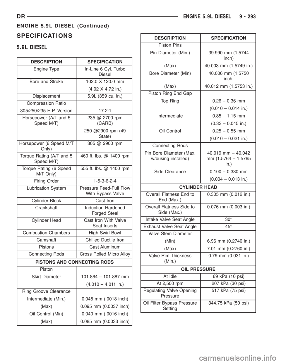
SPECIFICATIONS
5.9L DIESEL
DESCRIPTION SPECIFICATION
Engine Type In-Line 6 Cyl. Turbo
Diesel
Bore and Stroke 102.0 X 120.0 mm
(4.02 X 4.72 in.)
Displacement 5.9L (359 cu. in.)
Compression Ratio
305/250/235 H.P. Version 17.2:1
Horsepower (A/T and 5
Speed M/T)235 @ 2700 rpm
(CARB)
250 @2900 rpm (49
State)
Horsepower (6 Speed M/T
Only)305 @ 2900 rpm
Torque Rating (A/T and 5
Speed M/T)460 ft. lbs. @ 1400 rpm
Torque Rating (6 Speed
M/T Only)555 ft. lbs. @ 1400 rpm
Firing Order 1-5-3-6-2-4
Lubrication System Pressure Feed-Full Flow
With Bypass Valve
Cylinder Block Cast Iron
Crankshaft Induction Hardened
Forged Steel
Cylinder Head Cast Iron With Valve
Seat Inserts
Combustion Chambers High Swirl Bowl
Camshaft Chilled Ductile Iron
Pistons Cast Aluminum
Connecting Rods Cross Rolled Micro Alloy
PISTONS AND CONNECTING RODS
Piston
Skirt Diameter 101.864 ± 101.887 mm
(4.010 ± 4.011 in.)
Ring Groove Clearance
Intermediate (Min.) 0.045 mm (.0018 inch)
(Max) 0.095 mm (0.0037 inch)
Oil Control (Min) 0.040 mm (.0016 inch)
(Max) 0.085 mm (0.0033 inch)
DESCRIPTION SPECIFICATION
Piston Pins
Pin Diameter (Min.) 39.990 mm (1.5744
inch)
(Max) 40.003 mm (1.5749 in.)
Bore Diameter (Min) 40.006 mm (1.5750
inch.
(Max) 40.012 mm (1.5753 in.)
Piston Ring End Gap
Top Ring 0.26 ± 0.36 mm
(0.010 ± 0.014 in.)
Intermediate 0.85 ± 1.15 mm
(0.33 ± 0.045 in.)
Oil Control 0.25 ± 0.55 mm
(0.010 ± 0.021 in.)
Connecting Rods
Pin Bore Diameter (Max.
w/busing installed)40.019 mm ± 40.042
mm (1.5764 ± 1.5765
in.)
Side Clearance 0.100 ± 0.330 mm
(0.004 ± 0.013 in.)
CYLINDER HEAD
Overall Flatness End to
End (Max.)0.305 mm (0.012 in.)
Overall Flatness Side to
Side (Max.)0.076 mm (0.003 in.)
Intake Valve Seat Angle 30É
Exhaust Valve Seat Angle 45É
Valve Stem Diameter
(Min) 6.96 mm (0.2740 in.)
(Max) 7.01 mm (0.2760 in.)
Valve Rim Thickness
(Min.)0.79 mm (0.031 in.)
OIL PRESSURE
At Idle 69 kPa (10 psi)
At 2,500 rpm 207 kPa (30 psi)
Regulating Valve Opening
Pressure517 kPa (75 psi)
Oil Filter Bypass Pressure
Setting344.75 kPa (50 psi)
DRENGINE 5.9L DIESEL 9 - 293
ENGINE 5.9L DIESEL (Continued)
Page 1579 of 2895
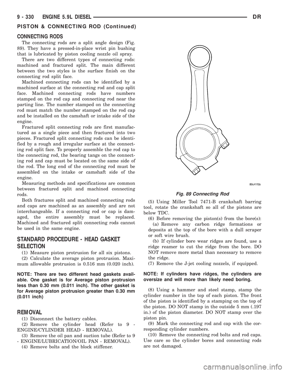
CONNECTING RODS
The connecting rods are a split angle design (Fig.
89). They have a pressed-in-place wrist pin bushing
that is lubricated by piston cooling nozzle oil spray.
There are two different types of connecting rods:
machined and fractured split. The main different
between the two styles is the surface finish on the
connecting rod split face.
Machined connecting rods can be identified by a
machined surface at the connecting rod and cap split
face. Machined connecting rods have numbers
stamped on the rod cap and connecting rod near the
parting line. The number stamped on the connecting
rod must match the number stamped on the rod cap
and be installed on the camshaft or intake side of the
engine.
Fractured split connecting rods are first manufac-
tured as a single piece and then fractured into two
pieces. Fractured split connecting rods can be identi-
fied by a rough and irregular surface at the connect-
ing rod split face. To properly assemble the rod cap to
the connecting rod, the bearing tangs on the connect-
ing rod and cap must be located on the same side of
the rod. The long end of the connecting rod must be
assembled on the intake or camshaft side of the
engine.
Measuring methods and specifications are common
between fractured split and machined connecting
rods.
Both fractures split and machined connecting rods
and caps are machined as an assembly and are not
interchangeable. If a connecting rod or cap is dam-
aged, the entire assembly must be replaced.
Machined and fractured split connecting rods cannot
be used in the same engine.
STANDARD PROCEDURE - HEAD GASKET
SELECTION
(1) Measure piston protrusion for all six pistons.
(2) Calculate the average piston protrusion. Maxi-
mum allowable protrusion is 0.516 mm (0.020 inch).
NOTE: There are two different head gaskets avail-
able. One gasket is for Average piston protrusion
less than 0.30 mm (0.011 inch). The other gasket is
for Average piston protrusion greater than 0.30 mm
(0.011 inch)
REMOVAL
(1) Disconnect the battery cables.
(2) Remove the cylinder head (Refer to 9 -
ENGINE/CYLINDER HEAD - REMOVAL).
(3) Remove the oil pan and suction tube (Refer to 9
- ENGINE/LUBRICATION/OIL PAN - REMOVAL).
(4) Remove bolts and the block stiffener.(5) Using Miller Tool 7471-B crankshaft barring
tool, rotate the crankshaft so all of the pistons are
below TDC.
(6) Before removing the piston(s) from the bore(s):
(a) Remove any carbon ridge formations or
deposits at the top of the bore with a dull scraper
or soft wire brush.
(b) If cylinder bore wear ridges are found, use a
ridge reamer to cut the ridge from the bore. DO
NOT remove more metal than necessary to remove
the ridge.
(7) Remove the J-jet cooling nozzels, if equipped.
NOTE: If cylinders have ridges, the cylinders are
oversize and will more than likely need boring.
(8) Using a hammer and steel stamp, stamp the
cylinder number in the top of each piston. The front
of the piston is identified by a stamping on the top of
the piston. DO NOT stamp in the outside 5 mm (.197
in.) of the piston diameter. DO NOT stamp over the
piston pin.
(9) Mark the connecting rod and cap with the cor-
responding cylinder numbers.
(10) Remove the connecting rod bolts and rod caps.
Use care so the cylinder bores and connecting rods
are not damaged.
Fig. 89 Connecting Rod
9 - 330 ENGINE 5.9L DIESELDR
PISTON & CONNECTING ROD (Continued)
Page 1581 of 2895
Inspect the piston pin for nicks, gouges and exces-
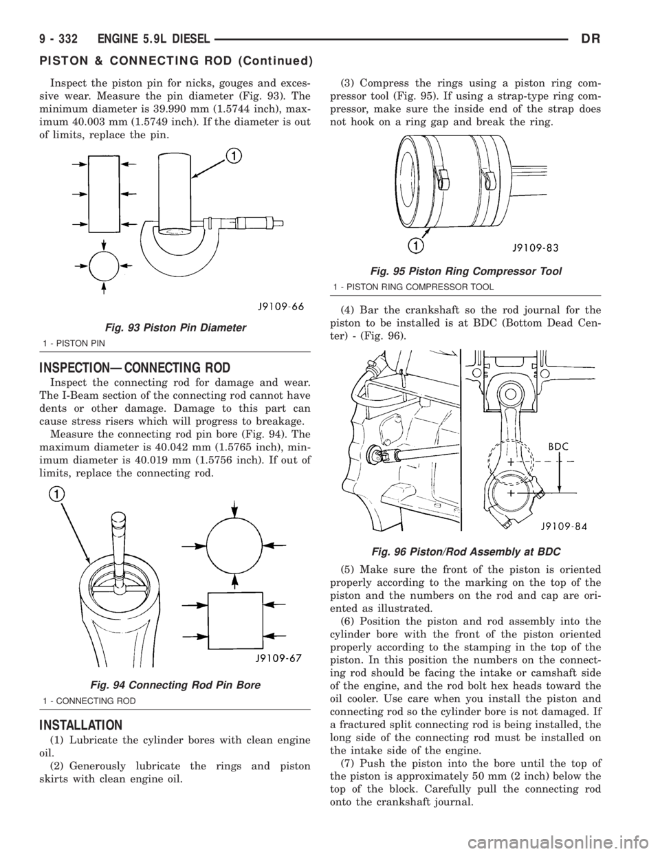
sive wear. Measure the pin diameter (Fig. 93). The
minimum diameter is 39.990 mm (1.5744 inch), max-
imum 40.003 mm (1.5749 inch). If the diameter is out
of limits, replace the pin.
INSPECTIONÐCONNECTING ROD
Inspect the connecting rod for damage and wear.
The I-Beam section of the connecting rod cannot have
dents or other damage. Damage to this part can
cause stress risers which will progress to breakage.
Measure the connecting rod pin bore (Fig. 94). The
maximum diameter is 40.042 mm (1.5765 inch), min-
imum diameter is 40.019 mm (1.5756 inch). If out of
limits, replace the connecting rod.
INSTALLATION
(1) Lubricate the cylinder bores with clean engine
oil.
(2) Generously lubricate the rings and piston
skirts with clean engine oil.(3) Compress the rings using a piston ring com-
pressor tool (Fig. 95). If using a strap-type ring com-
pressor, make sure the inside end of the strap does
not hook on a ring gap and break the ring.
(4) Bar the crankshaft so the rod journal for the
piston to be installed is at BDC (Bottom Dead Cen-
ter) - (Fig. 96).
(5) Make sure the front of the piston is oriented
properly according to the marking on the top of the
piston and the numbers on the rod and cap are ori-
ented as illustrated.
(6) Position the piston and rod assembly into the
cylinder bore with the front of the piston oriented
properly according to the stamping in the top of the
piston. In this position the numbers on the connect-
ing rod should be facing the intake or camshaft side
of the engine, and the rod bolt hex heads toward the
oil cooler. Use care when you install the piston and
connecting rod so the cylinder bore is not damaged. If
a fractured split connecting rod is being installed, the
long side of the connecting rod must be installed on
the intake side of the engine.
(7) Push the piston into the bore until the top of
the piston is approximately 50 mm (2 inch) below the
top of the block. Carefully pull the connecting rod
onto the crankshaft journal.
Fig. 93 Piston Pin Diameter
1 - PISTON PIN
Fig. 94 Connecting Rod Pin Bore
1 - CONNECTING ROD
Fig. 95 Piston Ring Compressor Tool
1 - PISTON RING COMPRESSOR TOOL
Fig. 96 Piston/Rod Assembly at BDC
9 - 332 ENGINE 5.9L DIESELDR
PISTON & CONNECTING ROD (Continued)
Page 1582 of 2895
(8) Use clean engine oil to lubricate the threads
and under the heads of the connecting rod bolts.
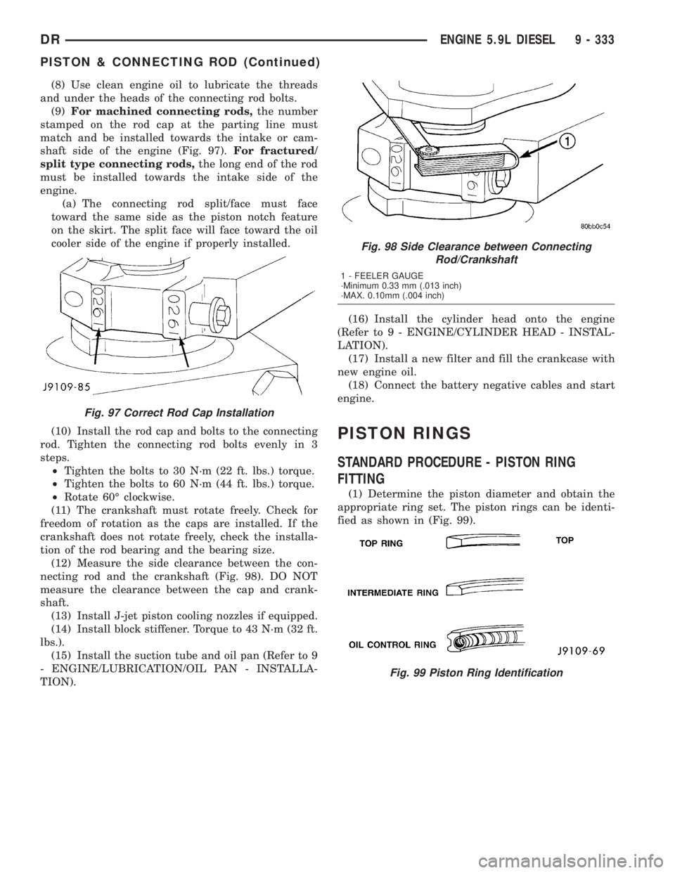
(9)For machined connecting rods,the number
stamped on the rod cap at the parting line must
match and be installed towards the intake or cam-
shaft side of the engine (Fig. 97).For fractured/
split type connecting rods,the long end of the rod
must be installed towards the intake side of the
engine.
(a) The connecting rod split/face must face
toward the same side as the piston notch feature
on the skirt. The split face will face toward the oil
cooler side of the engine if properly installed.
(10) Install the rod cap and bolts to the connecting
rod. Tighten the connecting rod bolts evenly in 3
steps.
²Tighten the bolts to 30 N´m (22 ft. lbs.) torque.
²Tighten the bolts to 60 N´m (44 ft. lbs.) torque.
²Rotate 60É clockwise.
(11) The crankshaft must rotate freely. Check for
freedom of rotation as the caps are installed. If the
crankshaft does not rotate freely, check the installa-
tion of the rod bearing and the bearing size.
(12) Measure the side clearance between the con-
necting rod and the crankshaft (Fig. 98). DO NOT
measure the clearance between the cap and crank-
shaft.
(13) Install J-jet piston cooling nozzles if equipped.
(14) Install block stiffener. Torque to 43 N´m (32 ft.
lbs.).
(15) Install the suction tube and oil pan (Refer to 9
- ENGINE/LUBRICATION/OIL PAN - INSTALLA-
TION).(16) Install the cylinder head onto the engine
(Refer to 9 - ENGINE/CYLINDER HEAD - INSTAL-
LATION).
(17) Install a new filter and fill the crankcase with
new engine oil.
(18) Connect the battery negative cables and start
engine.
PISTON RINGS
STANDARD PROCEDURE - PISTON RING
FITTING
(1) Determine the piston diameter and obtain the
appropriate ring set. The piston rings can be identi-
fied as shown in (Fig. 99).
Fig. 97 Correct Rod Cap Installation
Fig. 98 Side Clearance between Connecting
Rod/Crankshaft
1 - FEELER GAUGE
´Minimum 0.33 mm (.013 inch)
´MAX. 0.10mm (.004 inch)
Fig. 99 Piston Ring Identification
DRENGINE 5.9L DIESEL 9 - 333
PISTON & CONNECTING ROD (Continued)
Page 1586 of 2895
REAR MOUNT
REMOVAL
(1) Raise the vehicle on a hoist.
(2) Position a transmission jack in place.
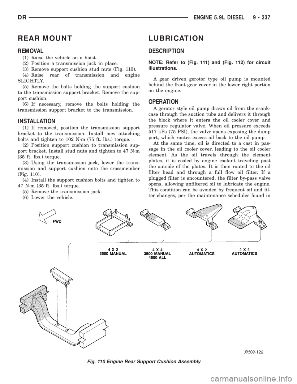
(3) Remove support cushion stud nuts (Fig. 110).
(4) Raise rear of transmission and engine
SLIGHTLY.
(5) Remove the bolts holding the support cushion
to the transmission support bracket. Remove the sup-
port cushion.
(6) If necessary, remove the bolts holding the
transmission support bracket to the transmission.
INSTALLATION
(1) If removed, position the transmission support
bracket to the transmission. Install new attaching
bolts and tighten to 102 N´m (75 ft. lbs.) torque.
(2) Position support cushion to transmission sup-
port bracket. Install stud nuts and tighten to 47 N´m
(35 ft. lbs.) torque.
(3) Using the transmission jack, lower the trans-
mission and support cushion onto the crossmember
(Fig. 110).
(4) Install the support cushion bolts and tighten to
47 N´m (35 ft. lbs.) torque.
(5) Remove the transmission jack.
(6) Lower the vehicle.
LUBRICATION
DESCRIPTION
NOTE: Refer to (Fig. 111) and (Fig. 112) for circuit
illustrations.
A gear driven gerotor type oil pump is mounted
behind the front gear cover in the lower right portion
on the engine.
OPERATION
A gerotor style oil pump draws oil from the crank-
case through the suction tube and delivers it through
the block where it enters the oil cooler cover and
pressure regulator valve. When oil pressure exceeds
517 kPa (75 PSI), the valve opens exposing the dump
port, which routes excess oil back to the oil pump.
At the same time, oil is directed to a cast in pas-
sage in the oil cooler cover, leading to the oil cooler
element. As the oil travels through the element
plates, it is cooled by engine coolant traveling past
the outside of the plates. It is then routed to the oil
filter head and through a full flow oil filter. If a
plugged filter is encountered, the filter by-pass valve
opens, allowing unfiltered oil to lubricate the engine.
This condition can be avoided by frequent oil and fil-
ter changes, per the maintenance schedules found in
Fig. 110 Engine Rear Support Cushion Assembly
DRENGINE 5.9L DIESEL 9 - 337
Page 1590 of 2895
OIL
STANDARD PROCEDURE
STANDARD PROCEDURE - ENGINE OIL LEVEL
CAUTION: Do not overfill crankcase with engine oil,
oil foaming and oil pressure loss can result.
To ensure proper lubrication of an engine, the
engine oil must be maintained at an acceptable level.
The acceptable oil level is in the SAFE RANGE on
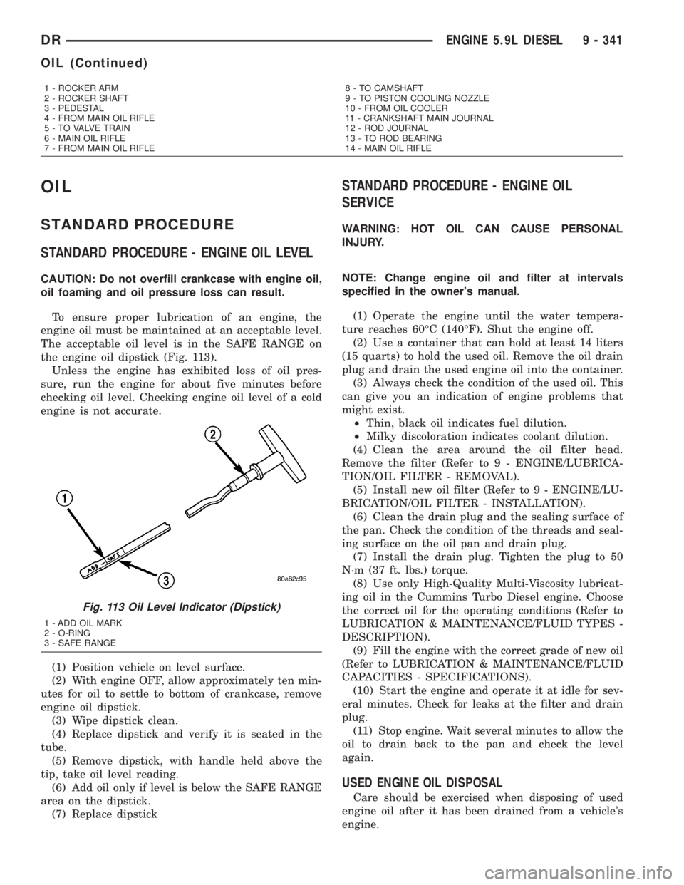
the engine oil dipstick (Fig. 113).
Unless the engine has exhibited loss of oil pres-
sure, run the engine for about five minutes before
checking oil level. Checking engine oil level of a cold
engine is not accurate.
(1) Position vehicle on level surface.
(2) With engine OFF, allow approximately ten min-
utes for oil to settle to bottom of crankcase, remove
engine oil dipstick.
(3) Wipe dipstick clean.
(4) Replace dipstick and verify it is seated in the
tube.
(5) Remove dipstick, with handle held above the
tip, take oil level reading.
(6) Add oil only if level is below the SAFE RANGE
area on the dipstick.
(7) Replace dipstick
STANDARD PROCEDURE - ENGINE OIL
SERVICE
WARNING: HOT OIL CAN CAUSE PERSONAL
INJURY.
NOTE: Change engine oil and filter at intervals
specified in the owner's manual.
(1) Operate the engine until the water tempera-
ture reaches 60ÉC (140ÉF). Shut the engine off.
(2) Use a container that can hold at least 14 liters
(15 quarts) to hold the used oil. Remove the oil drain
plug and drain the used engine oil into the container.
(3) Always check the condition of the used oil. This
can give you an indication of engine problems that
might exist.
²Thin, black oil indicates fuel dilution.
²Milky discoloration indicates coolant dilution.
(4) Clean the area around the oil filter head.
Remove the filter (Refer to 9 - ENGINE/LUBRICA-
TION/OIL FILTER - REMOVAL).
(5) Install new oil filter (Refer to 9 - ENGINE/LU-
BRICATION/OIL FILTER - INSTALLATION).
(6) Clean the drain plug and the sealing surface of
the pan. Check the condition of the threads and seal-
ing surface on the oil pan and drain plug.
(7) Install the drain plug. Tighten the plug to 50
N´m (37 ft. lbs.) torque.
(8) Use only High-Quality Multi-Viscosity lubricat-
ing oil in the Cummins Turbo Diesel engine. Choose
the correct oil for the operating conditions (Refer to
LUBRICATION & MAINTENANCE/FLUID TYPES -
DESCRIPTION).
(9) Fill the engine with the correct grade of new oil
(Refer to LUBRICATION & MAINTENANCE/FLUID
CAPACITIES - SPECIFICATIONS).
(10) Start the engine and operate it at idle for sev-
eral minutes. Check for leaks at the filter and drain
plug.
(11) Stop engine. Wait several minutes to allow the
oil to drain back to the pan and check the level
again.
USED ENGINE OIL DISPOSAL
Care should be exercised when disposing of used
engine oil after it has been drained from a vehicle's
engine.
1 - ROCKER ARM
2 - ROCKER SHAFT
3 - PEDESTAL
4 - FROM MAIN OIL RIFLE
5 - TO VALVE TRAIN
6 - MAIN OIL RIFLE
7 - FROM MAIN OIL RIFLE8 - TO CAMSHAFT
9 - TO PISTON COOLING NOZZLE
10 - FROM OIL COOLER
11 - CRANKSHAFT MAIN JOURNAL
12 - ROD JOURNAL
13 - TO ROD BEARING
14 - MAIN OIL RIFLE
Fig. 113 Oil Level Indicator (Dipstick)
1 - ADD OIL MARK
2 - O-RING
3 - SAFE RANGE
DRENGINE 5.9L DIESEL 9 - 341
OIL (Continued)
Page 1591 of 2895
OIL COOLER & LINES
CLEANING
CLEANING AND INSPECTION
Clean the sealing surfaces.
Apply 483 kPa (70 psi) air pressure to the element
to check for leaks. If the element leaks, replace the
element.
OIL FILTER
REMOVAL
(1) Clean the area around the oil filter head.
Remove the filter from below using a cap-style filter
wrench.
(2) Clean the gasket surface of the filter head. The
filter canister O-Ring seal can stick on the filter
head. Make sure it is removed.
INSTALLATION
(1) Fill the oil filter element with clean oil before
installation. Use the same type oil that will be used
in the engine.
(2) Apply a light film of lubricating oil to the seal-
ing surface before installing the filter.
CAUTION: Mechanical over-tightening may distort
the threads or damage the filter element seal.
(3) Install the filter until it contacts the sealing
surface of the oil filter adapter. Tighten filter an
additional
1¤2turn.
OIL PAN
REMOVAL
(1) Disconnect the battery negative cables.
(2) Install engine support fixture # 8534.
(3) Raise vehicle on hoist.
(4) Disconnect starter cables from starter motor.
(5) Remove starter motor (Refer to 8 - ELECTRI-
CAL/STARTING/STARTER MOTOR - REMOVAL)
and transmission adapter plate assembly.
(6) Remove transmission and transfer case (if
equipped).
(7) Remove flywheel or flexplate.
(8) Remove the transmission adapter plate.
WARNING: HOT OIL CAN CAUSE PERSONAL
INJURY.
(9) Drain the engine oil (Refer to 9 - ENGINE/LU-
BRICATION/OIL - STANDARD PROCEDURE).(10) Install the oil pan drain plug if sealing sur-
face is not damaged and tighten to 50 N´m (57 ft.
lbs.) torque.
(11) Remove oil pan bolts, break the pan to block
seal, and lower pan slightly and remove oil suction
tube fasteners.
(12) Remove oil pan and suction tube.
CLEANING
Remove all gasket material from the oil pan and
cylinder block sealing surfaces. Extra effort may be
required around T-joint areas. Clean oil pan and
flush suction tube with a suitable solvent.
INSPECTION
Inspect the oil pan, suction tube, and tube braces
for cracks and damage. Replace any defective compo-
nent. Inspect the oil drain plug and drain hole
threads. Inspect the oil pan sealing surface for
straightness. Repair any minor imperfections with a
ball-peen hammer. Do not attempt to repair an oil
pan by welding.
INSTALLATION
(1) Fill the T-joint between the pan rail/gear hous-
ing and pan rail/rear seal retainer with sealant. Use
MopartSilicone Rubber Adhesive Sealant or equiva-
lent.
(2) Place suction tube in oil pan and guide them
into place. Using a new tube to block gasket, install
and tighten the suction tube bolts by hand. Starting
with the oil pump inlet bolts, tighten the bolts to 24
N´m (18 ft. lbs.) torque. Tighten the remaining tube
brace bolts to 43 N´m (32 ft. lbs.) torque.
(3) Starting in the center and working outward,
tighten the oil pan bolts to 28 N´m (21 ft. lbs.)
torque.
(4) Install the flywheel housing assembly with the
starter motor attached and tighten bolts to 77 N´m
(57 ft. lbs.) torque.
(5) Connect starter motor cables.
(6) Install the flywheel or flexplate. Torque to 137
N´m (101 ft. lbs.).
(7) Install transmission and transfer case (if
equipped).
(8) Lower vehicle.
(9) Remove the engine support fixture # 8534.
(10) Install battery negative cables.
(11) Fill the crankcase with new engine oil.
(12) Start engine and check for leaks. Stop engine,
check oil level, and adjust, if necessary.
9 - 342 ENGINE 5.9L DIESELDR
Page 1602 of 2895
ENGINE 8.0L
DESCRIPTION
The 8.0 Liter (488 CID) ten-cylinder engine is a
V-Type lightweight, single cam, overhead valve
engine with hydraulic roller tappets. This engine is
designed for unleaded fuel.
Engine lubrication system consists of a gerotor
type oil pump mounted in the timing chain cover and
driven by the crankshaft. The V-10 uses a full flow
oil filter.
The cylinders are numbered from front to rear; 1,
3, 5, 7, 9 on the left bank and 2, 4, 6, 8, 10 on the
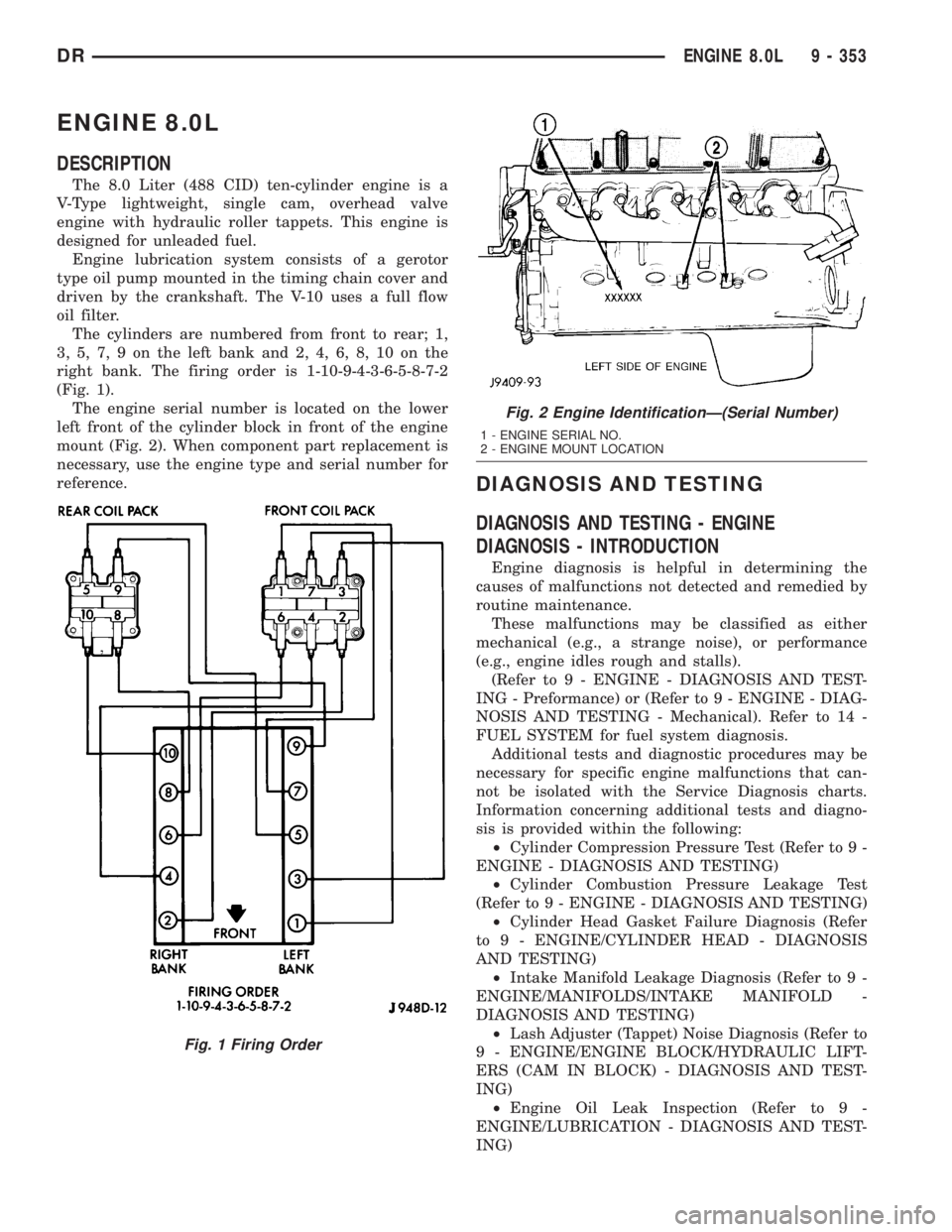
right bank. The firing order is 1-10-9-4-3-6-5-8-7-2
(Fig. 1).
The engine serial number is located on the lower
left front of the cylinder block in front of the engine
mount (Fig. 2). When component part replacement is
necessary, use the engine type and serial number for
reference.
DIAGNOSIS AND TESTING
DIAGNOSIS AND TESTING - ENGINE
DIAGNOSIS - INTRODUCTION
Engine diagnosis is helpful in determining the
causes of malfunctions not detected and remedied by
routine maintenance.
These malfunctions may be classified as either
mechanical (e.g., a strange noise), or performance
(e.g., engine idles rough and stalls).
(Refer to 9 - ENGINE - DIAGNOSIS AND TEST-
ING - Preformance) or (Refer to 9 - ENGINE - DIAG-
NOSIS AND TESTING - Mechanical). Refer to 14 -
FUEL SYSTEM for fuel system diagnosis.
Additional tests and diagnostic procedures may be
necessary for specific engine malfunctions that can-
not be isolated with the Service Diagnosis charts.
Information concerning additional tests and diagno-
sis is provided within the following:
²Cylinder Compression Pressure Test (Refer to 9 -
ENGINE - DIAGNOSIS AND TESTING)
²Cylinder Combustion Pressure Leakage Test
(Refer to 9 - ENGINE - DIAGNOSIS AND TESTING)
²Cylinder Head Gasket Failure Diagnosis (Refer
to 9 - ENGINE/CYLINDER HEAD - DIAGNOSIS
AND TESTING)
²Intake Manifold Leakage Diagnosis (Refer to 9 -
ENGINE/MANIFOLDS/INTAKE MANIFOLD -
DIAGNOSIS AND TESTING)
²Lash Adjuster (Tappet) Noise Diagnosis (Refer to
9 - ENGINE/ENGINE BLOCK/HYDRAULIC LIFT-
ERS (CAM IN BLOCK) - DIAGNOSIS AND TEST-
ING)
²Engine Oil Leak Inspection (Refer to 9 -
ENGINE/LUBRICATION - DIAGNOSIS AND TEST-
ING)
Fig. 1 Firing Order
Fig. 2 Engine IdentificationÐ(Serial Number)
1 - ENGINE SERIAL NO.
2 - ENGINE MOUNT LOCATION
DRENGINE 8.0L 9 - 353