2003 DODGE RAM oil type
[x] Cancel search: oil typePage 2342 of 2895
washers. Petroleum jelly can also be used to hold
parts in place during reassembly.
Clean the case in a solvent tank. Flush the case
bores and fluid passages thoroughly with solvent.
Dry the case and all fluid passages with compressed
air. Be sure all solvent is removed from the case and
that all fluid passages are clear.
NOTE: Do not use shop towels or rags to dry the
case (or any other transmission component) unless
they are made from lint-free materials. Lint will stick
to case surfaces and transmission components and
circulate throughout the transmission after assem-
bly. A sufficient quantity of lint can block fluid pas-
sages and interfere with valve body operation.
INSPECTION
Inspect the case for cracks, porous spots, worn
bores, or damaged threads. Damaged threads can be
repaired with Helicoil thread inserts. However, the
case will have to be replaced if it exhibits any type of
damage or wear.
ASSEMBLY
(1) Clean and inspect all components. Replace any
components which show evidence of excessive wear
or scoring.
(2) Install the cooler filter bypass valve.
(3) Torque the bypass valve to specification. The
valve uses a tapered pipe thread and excessive
torque can damage the transmission case. Tighten
the cooler filter bypass valve to 4.5 N´m (40 in.lbs.).
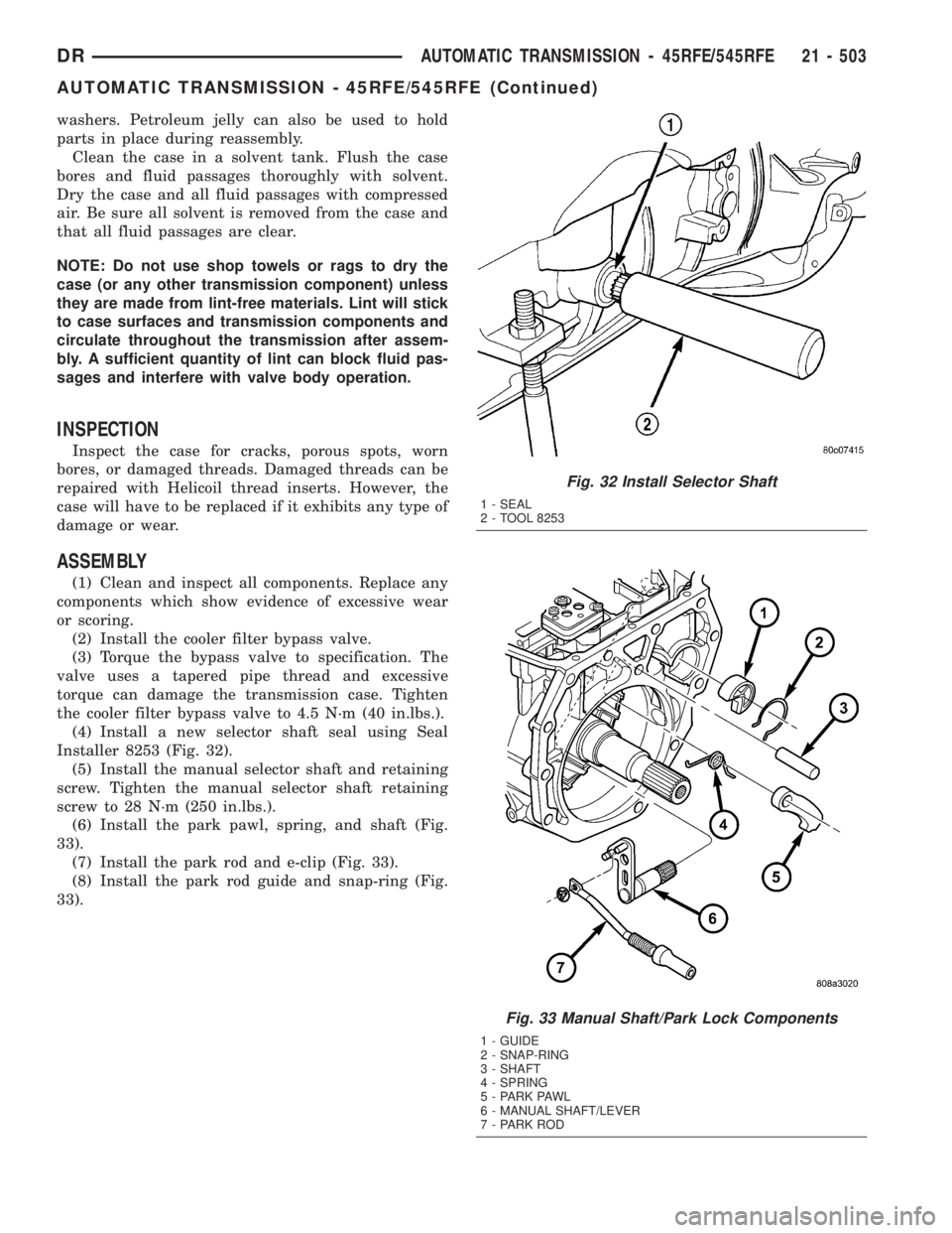
(4) Install a new selector shaft seal using Seal
Installer 8253 (Fig. 32).
(5) Install the manual selector shaft and retaining
screw. Tighten the manual selector shaft retaining
screw to 28 N´m (250 in.lbs.).
(6) Install the park pawl, spring, and shaft (Fig.
33).
(7) Install the park rod and e-clip (Fig. 33).
(8) Install the park rod guide and snap-ring (Fig.
33).
Fig. 32 Install Selector Shaft
1 - SEAL
2 - TOOL 8253
Fig. 33 Manual Shaft/Park Lock Components
1 - GUIDE
2 - SNAP-RING
3 - SHAFT
4 - SPRING
5 - PARK PAWL
6 - MANUAL SHAFT/LEVER
7 - PARK ROD
DRAUTOMATIC TRANSMISSION - 45RFE/545RFE 21 - 503
AUTOMATIC TRANSMISSION - 45RFE/545RFE (Continued)
Page 2578 of 2895
ROAD TESTING WIND NOISE
(1) Drive the vehicle to verify the general location
of the wind noise.
(2) Apply 50 mm (2 in.) masking tape in 150 mm
(6 in.) lengths along weatherstrips, weld seams or
moldings. After each length is applied, drive the vehi-
cle. If noise goes away after a piece of tape is applied,
remove tape, locate, and repair defect.
POSSIBLE CAUSE OF WIND NOISE
²Moldings standing away from body surface can
catch wind and whistle.
²Gaps in sealed areas behind overhanging body
flanges can cause wind-rushing sounds.
²Misaligned movable components.
²Missing or improperly installed plugs in pillars.
²Weld burn through holes.
STANDARD PROCEDURE
STANDARD PROCEDURE - BODY LUBRICATION
All mechanisms and linkages should be lubricated
when necessary. This will maintain ease of operation
and provide protection against rust and excessive
wear. The weatherstrip seals should be lubricated to
prolong their life as well as to improve door sealing.
All applicable exterior and interior vehicle operat-
ing mechanisms should be inspected and cleaned.
Pivot/sliding contact areas on the mechanisms should
then be lubricated.
(1) When necessary, lubricate the operating mech-
anisms with the specified lubricants.
(2) Apply silicone lubricant to a cloth and wipe it
on door seals to avoid over-spray that can soil pas-
senger's clothing.
(3) Before applying lubricant, the component
should be wiped clean. After lubrication, any excess
lubricant should be removed.
(4) The hood latch, latch release mechanism, latch
striker, and safety latch should be lubricated period-
ically.
(5) The door lock cylinders should be lubricated
twice each year (preferably autumn and spring).
²Spray a small amount of lock cylinder lubricant
directly into the lock cylinder.
²Apply a small amount to the key and insert it
into the lock cylinder.
²Rotate it to the locked position and then back to
the unlocked position several times.
²Remove the key. Wipe the lubricant from it with
a clean cloth to avoid soiling of clothing.
STANDARD PROCEDURE - HEAT STAKING
(1) Remove trim panel.(2) Bend or move the trim panel components at
the heat staked joints. Observe the heat staked loca-
tions and/or component seams for looseness.
(3) Heat stake the components.
(a) If the heat staked or component seam loca-
tion is loose, hold the two components tightly
together and using a soldering gun with a flat tip,
melt the material securing the components
together. Do not over heat the affected area, dam-
age to the exterior of the trim panel may occur.
(b) If the heat staked material is broken or miss-
ing, use a hot glue gun to apply new material to
the area to be repaired. The panels that are being
heat staked must be held together while the apply-
ing the glue. Once the new material is in place, it
may be necessary to use a soldering gun to melt
the newly applied material. Do not over heat the
affected area, damage to the exterior of the trim
panel may occur.
(4) Allow the repaired area to cool and verify the
repair.
(5) Install trim panel.
STANDARD PROCEDURE - PLASTIC BODY
PANEL REPAIR
There are many different types of plastics used in
today's automotive environment. We group plastics in
three different categories: Rigid, Semi-Rigid, and
Flexible. Any of these plastics may require the use of
an adhesion promoter for repair. These types of plas-
tic are used extensively on DaimlerChrysler Motors
vehicles. Always follow repair material manufactur-
er's plastic identification and repair procedures.
Rigid Plastics:
Examples of rigid plastic use: Fascias, Hoods,
Doors, and other Body Panels, which include SMC,
ABS, and Polycarbonates.
Semi-Rigid Plastics:
Examples of semi-rigid plastic use: Interior Panels,
Under Hood Panels, and other Body Trim Panels.
Flexible Plastics:
Examples of flexible plastic use: Fascias, Body
Moldings, and upper and lower Fascia Covers.
Repair Procedure:
The repair procedure for all three categories of
plastics is basically the same. The one difference is
the material used for the repair. The materials must
be specific for each substrate, rigid repair material
for rigid plastic repair, semi-rigid repair material for
semi-rigid plastic repair and flexible repair material
for flexible plastic repair.
DRBODY 23 - 3
BODY (Continued)
Page 2579 of 2895

Adhesion Promoter/Surface Modifier:
Adhesion Promoters/Surface Modifiers are required
for certain plastics. All three categories may have
plastics that require the use of adhesion promoter/
surface modifiers. Always follow repair material man-
ufacturer's plastic identification and repair
procedures.
SAFETY PRECAUTION AND WARNINGS
WARNING:
²EYE PROTECTION SHOULD BE USED WHEN
SERVICING COMPONENTS. PERSONAL INJURY
CAN RESULT.
²USE AN OSHA APPROVED BREATHING MASK
WHEN MIXING EPOXY, GRINDING, AND SPRAYING
PAINT OR SOLVENTS IN A CONFINED AREA. PER-
SONAL INJURY CAN RESULT.²AVOID PROLONGED SKIN CONTACT WITH
RESIN, PETROLEUM, OR ALCOHOL BASED SOL-
VENTS. PERSONAL INJURY CAN RESULT.
²DO NOT VENTURE UNDER A HOISTED VEHI-
CLE THAT IS NOT PROPERLY SUPPORTED ON
SAFETY STANDS. PERSONAL INJURY CAN
RESULT.
NOTE:
²When holes must be drilled or cut in body pan-
els, verify locations of internal body components
and electrical wiring. Damage to vehicle can result.
²Do not use abrasive chemicals or compounds
on undamaged painted surfaces around repair
areas. Damage to finish can result.
RIGID, SEMI-RIGID, AND FLEXIBLE PLASTIC PARTS TYPES
CODE FAMILY NAME COMMON TRADE NAME TYPICAL APPLICATION
ASA ACRYLONITRILE STYRENE
ACRYLITELURAN S CONSOLES, GRILLES
ABS ACRYLONITRILE
BUTADIENE STYRENETERLURAN9A9PILLARS, CONSOLES,
GRILLES
ABS/PC ABS/PC ALLOY PULSE, PROLOY,
BAYBLENDDOORS, INSTRUMENT
PANELS
ABS/PVC ABS/PV ALLOY PROLOY, PULSE, LUSTRAN,
CYCLOVINDOOR PANELS, GRILLES,
TRIM
BMC BULK MOLDING
COMPOUNDBMC FENDER EXTENSIONS
EMA EHTYLENE METHYL
ACRYLATE/IONOMERSURLYN, EMA, IONOMER BUMPER GUARDS, PADS
METTON METTON METTON GRILLES, KICK PANELS,
RUNNING BOARDS
MPPO MODIFIED
POLYPHENYLENE OXIDEMPPO SPOILER ASSEMBLY
PA POLYAMID ZYTEL, VYDYNE, PA,
MINLONFENDERS, QUARTER PANELS
PET THERMOPLASTIC
POLYESTERRYNITE TRIM
PBT/PPO PBT/PPO ALLOY GERMAX CLADDINGS
PBTP POLYBUTYLENE
THEREPTHALATEPBT, PBTP, POCAN, VALOX WHEEL COVERS, FENDERS,
GRILLES
PBTP/EEBC POLYBUTYLENE
THEREPTHALATE/EEBC
ALLOYBEXLOY,9M9, PBTP/EEBC FASCIAS, ROCKER PANEL,
MOLDINGS
PC POLYCARBONATE LEXAN, MERLON, CALIBRE,
MAKROLON PCTAIL LIGHT LENSES, IP TRIM,
VALANCE PANELS
23 - 4 BODYDR
BODY (Continued)
Page 2583 of 2895
should be stripped of paint and freed from wax and
oil. Scuff surfaces around repair area with 360 grit
wet/dry sandpaper, or equivalent, to assure adhesion
of repair materials.
PATCHING PANELS
An panel that has extensive puncture type damage
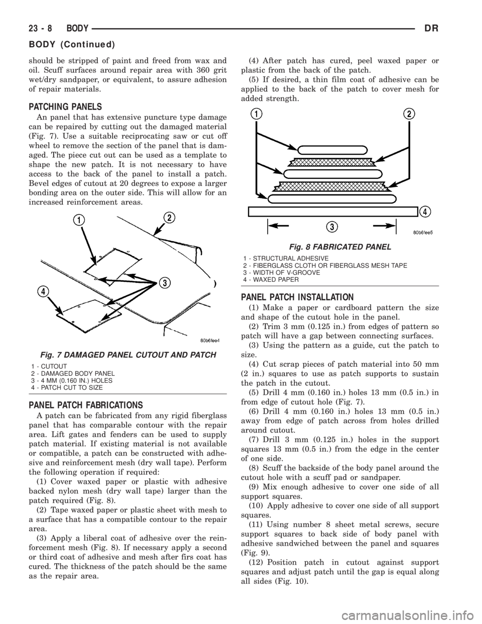
can be repaired by cutting out the damaged material
(Fig. 7). Use a suitable reciprocating saw or cut off
wheel to remove the section of the panel that is dam-
aged. The piece cut out can be used as a template to
shape the new patch. It is not necessary to have
access to the back of the panel to install a patch.
Bevel edges of cutout at 20 degrees to expose a larger
bonding area on the outer side. This will allow for an
increased reinforcement areas.
PANEL PATCH FABRICATIONS
A patch can be fabricated from any rigid fiberglass
panel that has comparable contour with the repair
area. Lift gates and fenders can be used to supply
patch material. If existing material is not available
or compatible, a patch can be constructed with adhe-
sive and reinforcement mesh (dry wall tape). Perform
the following operation if required:
(1) Cover waxed paper or plastic with adhesive
backed nylon mesh (dry wall tape) larger than the
patch required (Fig. 8).
(2) Tape waxed paper or plastic sheet with mesh to
a surface that has a compatible contour to the repair
area.
(3) Apply a liberal coat of adhesive over the rein-
forcement mesh (Fig. 8). If necessary apply a second
or third coat of adhesive and mesh after firs coat has
cured. The thickness of the patch should be the same
as the repair area.(4) After patch has cured, peel waxed paper or
plastic from the back of the patch.
(5) If desired, a thin film coat of adhesive can be
applied to the back of the patch to cover mesh for
added strength.
PANEL PATCH INSTALLATION
(1) Make a paper or cardboard pattern the size
and shape of the cutout hole in the panel.
(2) Trim 3 mm (0.125 in.) from edges of pattern so
patch will have a gap between connecting surfaces.
(3) Using the pattern as a guide, cut the patch to
size.
(4) Cut scrap pieces of patch material into 50 mm
(2 in.) squares to use as patch supports to sustain
the patch in the cutout.
(5) Drill 4 mm (0.160 in.) holes 13 mm (0.5 in.) in
from edge of cutout hole (Fig. 7).
(6) Drill 4 mm (0.160 in.) holes 13 mm (0.5 in.)
away from edge of patch across from holes drilled
around cutout.
(7) Drill 3 mm (0.125 in.) holes in the support
squares 13 mm (0.5 in.) from the edge in the center
of one side.
(8) Scuff the backside of the body panel around the
cutout hole with a scuff pad or sandpaper.
(9) Mix enough adhesive to cover one side of all
support squares.
(10) Apply adhesive to cover one side of all support
squares.
(11) Using number 8 sheet metal screws, secure
support squares to back side of body panel with
adhesive sandwiched between the panel and squares
(Fig. 9).
(12) Position patch in cutout against support
squares and adjust patch until the gap is equal along
all sides (Fig. 10).
Fig. 7 DAMAGED PANEL CUTOUT AND PATCH
1 - CUTOUT
2 - DAMAGED BODY PANEL
3-4MM(0.160 IN.) HOLES
4 - PATCH CUT TO SIZE
Fig. 8 FABRICATED PANEL
1 - STRUCTURAL ADHESIVE
2 - FIBERGLASS CLOTH OR FIBERGLASS MESH TAPE
3 - WIDTH OF V-GROOVE
4 - WAXED PAPER
23 - 8 BODYDR
BODY (Continued)
Page 2782 of 2895
STANDARD PROCEDURE - DIODE
REPLACEMENT
(1) Disconnect the battery negative cable and iso-
late it. If vehicle has a dual batterys remove both
negative cables.
(2) Locate the diode in the harness, and remove
the protective covering.
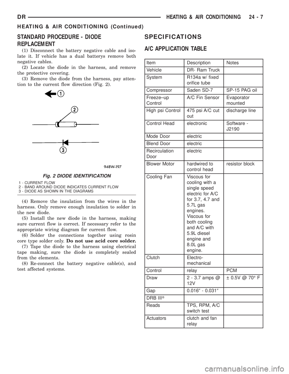
(3) Remove the diode from the harness, pay atten-
tion to the current flow direction (Fig. 2).
(4) Remove the insulation from the wires in the
harness. Only remove enough insulation to solder in
the new diode.
(5) Install the new diode in the harness, making
sure current flow is correct. If necessary refer to the
appropriate wiring diagram for current flow.
(6) Solder the connections together using rosin
core type solder only.Do not use acid core solder.
(7) Tape the diode to the harness using electrical
tape making, sure the diode is completely sealed
from the elements.
(8) Re-connect the battery negative cable(s), and
test affected systems.
SPECIFICATIONS
A/C APPLICATION TABLE
Item Description Notes
Vehicle DR- Ram Truck
System R134a w/ fixed
orifice tube
Compressor Saden SD-7 SP-15 PAG oil
Freeze±up
ControlA/C Fin Sensor Evaporator
mounted
High psi Control 475 psi A/C cut
outdischarge line
Control Head electronic Software -
J2190
Mode Door electric
Blend Door electric
Recirculation
Doorelectric
Blower Motor hardwired to
control headresistor block
Cooling Fan Viscous for
cooling with a
single speed
electric for A/C
for 3.7, 4.7 and
5.7L gas
engines.
Viscous for
both cooling
and A/C with
5.9L diesel
engine and
8.0L gas
engine.
Clutch Electro-
mechanical
Control relay PCM
Draw 2 - 3.7 amps @
12V 0.5V @ 70É F
Gap 0.0169- 0.0319
DRB IIIT
Reads TPS, RPM, A/C
switch test
Actuators clutch and fan
relay
Fig. 2 DIODE IDENTIFICATION
1 - CURRENT FLOW
2 - BAND AROUND DIODE INDICATES CURRENT FLOW
3 - DIODE AS SHOWN IN THE DIAGRAMS
DRHEATING & AIR CONDITIONING 24 - 7
HEATING & AIR CONDITIONING (Continued)
Page 2785 of 2895
seconds. Refer to Electronic Control Modules for
more information on the JTEC controls.
DIAGNOSIS AND TESTING - A/C COMPRESSOR
CLUTCH COIL
For circuit descriptions and diagrams, (Refer to
Appropriate Wiring Information). The battery must
be fully-charged before performing the following
tests. Refer to Battery for more information.
(1) Connect an ammeter (0 to 10 ampere scale) in
series with the clutch coil terminal. Use a voltmeter
(0 to 20 volt scale) with clip-type leads for measuring
the voltage across the battery and the compressor
clutch coil.
(2) With the A/C Heater mode control switch in
any A/C mode, and the blower motor switch in the
lowest speed position, start the engine and run it at
normal idle.
(3) The compressor clutch coil voltage should read
within 0.2 volts of the battery voltage. If there is
voltage at the clutch coil, but the reading is not
within 0.2 volts of the battery voltage, test the clutch
coil feed circuit for excessive voltage drop and repair
as required. If there is no voltage reading at the
clutch coil, use a DRB IIItscan tool and (Refer to
Appropriate Diagnostic Information) for testing of the
compressor clutch circuit and PCM control. The fol-
lowing components must be checked and repaired as
required before you can complete testing of the clutch
coil:
²Fuses in the junction block and the Power Dis-
tribution Center (PDC)
²A/C heater mode control switch
²Compressor clutch relay
²A/C high pressure transducer switch²JTEC
(4) The compressor clutch coil is acceptable if the
current draw measured at the clutch coil is 2.0 to 3.9
amperes with the electrical system voltage at 11.5 to
12.5 volts. This should only be checked with the work
area temperature at 21É C (70É F). If system voltage
is more than 12.5 volts, add electrical loads by turn-
ing on electrical accessories until the system voltage
drops below 12.5 volts.
(a) If the clutch coil current reading is four
amperes or more, the coil is shorted and should be
replaced.
(b) If the clutch coil current reading is zero, the
coil is open and should be replaced.
STANDARD PROCEDURE - A/C COMPRESSOR
CLUTCH BREAK-IN
After a new compressor clutch has been installed,
cycle the compressor clutch approximately twenty
times (five seconds on, then five seconds off). During
this procedure, set the A/C Heater control to the
Recirculation Mode, the blower motor switch in the
highest speed position, and the engine speed at 1500
to 2000 rpm. This procedure (burnishing) will seat
the opposing friction surfaces and provide a higher
compressor clutch torque capability.
REMOVAL
The refrigerant system can remain fully-charged
during compressor clutch, rotor, or coil replacement.
The compressor clutch can be serviced in the vehicle.
(1) Disconnect and isolate the battery negative
cable.
(2) Remove the serpentine drive belt(Refer to 7 -
COOLING/ACCESSORY DRIVE/DRIVE BELTS -
REMOVAL).
(3) Unplug the compressor clutch coil wire harness
connector.
(4) Remove the bolts that secure the compressor to
the mounting bracket.
(5) Remove the compressor from the mounting
bracket. Support the compressor in the engine com-
partment while servicing the clutch.
(6) Insert the two pins of the spanner wrench
(Special Tool C-4489 or equivalent) into the holes of
the clutch plate. Hold the clutch plate stationary and
remove the hex nut (Fig. 2).
(7) Remove the clutch plate.
(8) Remove the compressor clutch shims.
(9) Remove the external front housing snap ring
with snap ring pliers (Fig. 3).
(10)
Install the lip of the rotor puller (Special Tool
C-6141-1 or equivalent) into the snap ring groove
exposed in the previous step, and install the shaft pro-
tector (Special Tool C-6141-2 or equivalent) (Fig. 4).
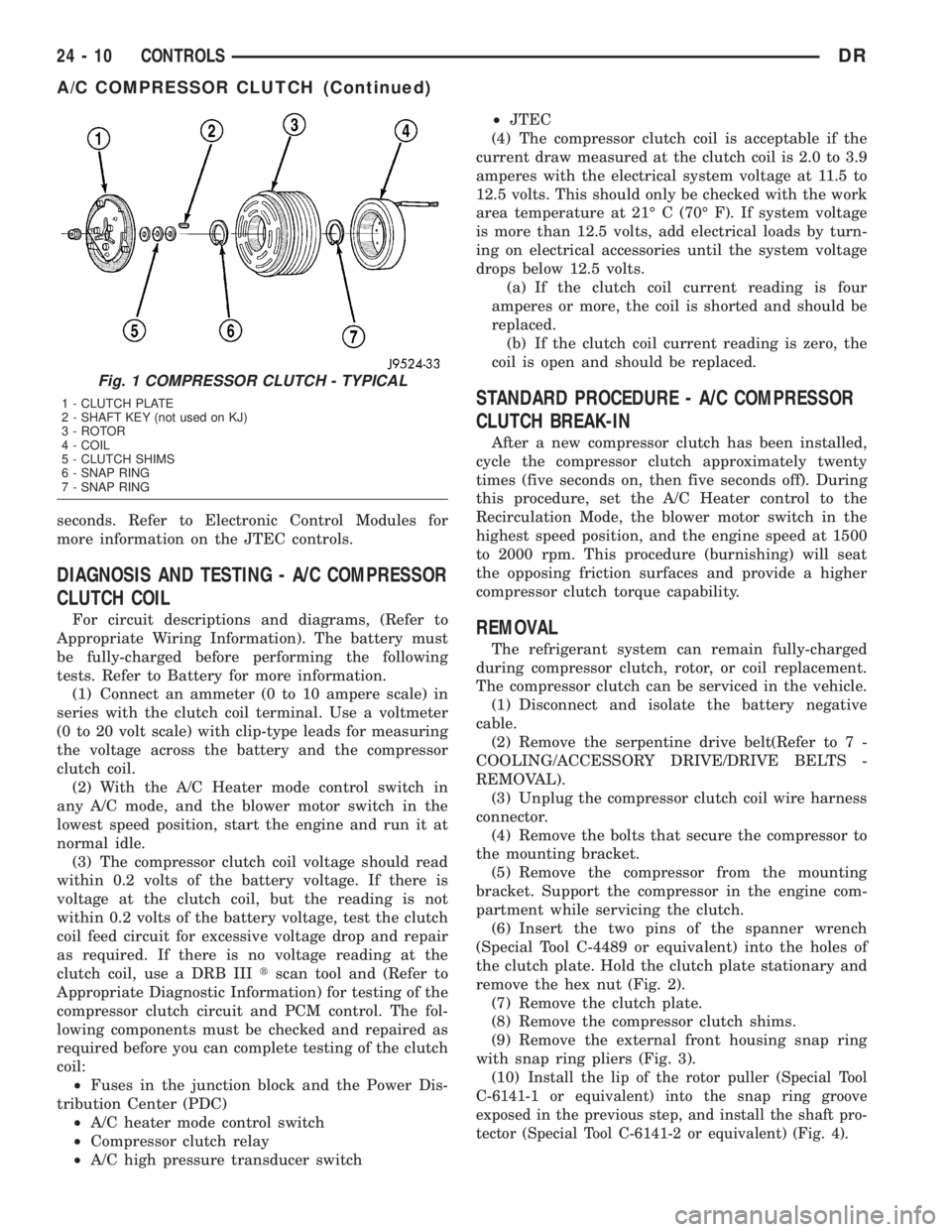
Fig. 1 COMPRESSOR CLUTCH - TYPICAL
1 - CLUTCH PLATE
2 - SHAFT KEY (not used on KJ)
3 - ROTOR
4 - COIL
5 - CLUTCH SHIMS
6 - SNAP RING
7 - SNAP RING
24 - 10 CONTROLSDR
A/C COMPRESSOR CLUTCH (Continued)
Page 2789 of 2895
for relay terminal 86 with the ignition switch in the
On position. If OK, go to Step 5. If not OK, repair the
open circuit to the fuse in the junction block as
required.
(5) The coil ground terminal cavity (85) is switched
to ground through the Powertrain Control Module
(PCM). There should be continuity between this cav-
ity and the A/C compressor clutch relay control cir-
cuit cavity of the PCM wire harness connector C
(gray) at all times. If not OK, repair the open circuit
as required.
REMOVAL
(1) Disconnect and isolate the battery negative
cable.
(2) Remove the cover from the Power Distribution
Center (PDC).
(3) Refer to the label on the PDC for compressor
clutch relay identification and location.
(4) Unplug the compressor clutch relay from the
PDC.
INSTALLATION
(1) Install the compressor clutch relay by aligning
the relay terminals with the cavities in the PDC and
pushing the relay firmly into place.
(2) Install the PDC cover.
(3) Connect the battery negative cable.
(4) Test the relay operation.
A/C HEATER CONTROL
DESCRIPTION
The A/C heater system uses a seriers of electrical
controls. These controls provide the vehicle operator
with a number of setting options to help control the
climate and comfort within the vehicle. Refer to the
owner's manual in the vehicle glove box for more
information on the features, use, and suggested oper-
ation of these controls.
The A/C heater control - (Single Zone) or (Dual
Zone) panel is located to the right of the instrument
cluster on the instrument panel.
The control panel contains a rotary-type tempera-
ture control, a rotary-type mode control switch knob,
and a rotary-type blower motor speed switch knob.
The control also has a push button to activate the
Optional side view mirrors defroster elements and to
turn the A/C on.
The Dual Zone HVAC control panel contains a pair
of slider-type temperature controls, a rotary-type
mode control switch knob and a rotary-type blower
motor speed switch knob. The control also has but-
tons to turn the A/C ON, Set it on Max A/C and for
the Optional Heated Sideview Mirrors.The A/C heater control panel cannot be repaired. If
faulty or damaged, the entire unit must be replaced.
The illumination lamps are available for service
replacement.
REMOVAL
WARNING: ON VEHICLES EQUIPPED WITH AIR-
BAGS, DISABLE THE AIRBAG SYSTEM BEFORE
ATTEMPTING ANY STEERING WHEEL, STEERING
COLUMN, OR INSTRUMENT PANEL COMPONENT
DIAGNOSIS OR SERVICE. DISCONNECT AND ISO-
LATE THE BATTERY NEGATIVE (GROUND) CABLE,
THEN WAIT TWO MINUTES FOR THE AIRBAG SYS-
TEM CAPACITOR TO DISCHARGE BEFORE PER-
FORMING FURTHER DIAGNOSIS OR SERVICE. THIS
IS THE ONLY SURE WAY TO DISABLE THE AIRBAG
SYSTEM. FAILURE TO TAKE THE PROPER PRE-
CAUTIONS COULD RESULT IN AN ACCIDENTAL
AIRBAG DEPLOYMENT AND POSSIBLE PERSONAL
INJURY.
(1) Disconnect and isolate the battery negative
cable.
(2) Remove the center bezel from the instrument
panel(Refer to 23 - BODY/INSTRUMENT PANEL/IN-
STRUMENT PANEL CENTER BEZEL - REMOVAL).
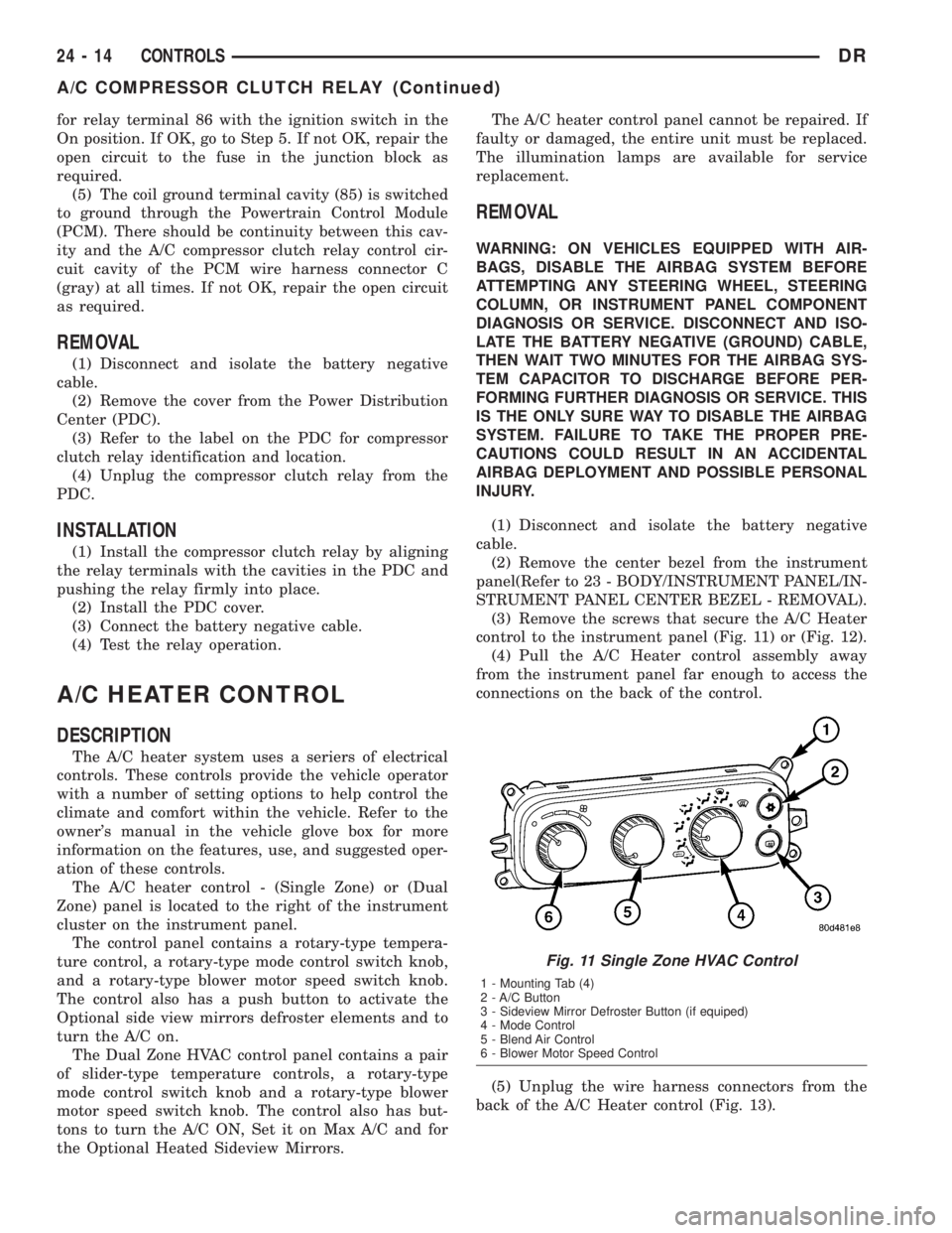
(3) Remove the screws that secure the A/C Heater
control to the instrument panel (Fig. 11) or (Fig. 12).
(4) Pull the A/C Heater control assembly away
from the instrument panel far enough to access the
connections on the back of the control.
(5) Unplug the wire harness connectors from the
back of the A/C Heater control (Fig. 13).
Fig. 11 Single Zone HVAC Control
1 - Mounting Tab (4)
2 - A/C Button
3 - Sideview Mirror Defroster Button (if equiped)
4 - Mode Control
5 - Blend Air Control
6 - Blower Motor Speed Control
24 - 14 CONTROLSDR
A/C COMPRESSOR CLUTCH RELAY (Continued)
Page 2808 of 2895
CAUTION
SERVICE CAUTIONS
CAUTION: Liquid refrigerant is corrosive to metal
surfaces. Follow the operating instructions supplied
with the service equipment being used.
Never add R-12 to a refrigerant system designed to
use R-134a. Damage to the system will result.
R-12 refrigerant oil must not be mixed with R-134a
refrigerant oil. They are not compatible.
Do not use R-12 equipment or parts on the R-134a
system. Damage to the system will result.
Do not overcharge the refrigerant system. This will
cause excessive compressor head pressure and
can cause noise and system failure.
Recover the refrigerant before opening any fitting
or connection. Open the fittings with caution, even
after the system has been discharged. Never open
or loosen a connection before recovering the refrig-
erant.
Do not remove the secondary retention clip from
any spring-lock coupler connection while the refrig-
erant system is under pressure. Recover the refrig-
erant before removing the secondary retention clip.
Open the fittings with caution, even after the sys-
tem has been discharged. Never open or loosen a
connection before recovering the refrigerant.
The refrigerant system must always be evacuated
before charging.
Do not open the refrigerant system or uncap a
replacement component until you are ready to ser-
vice the system. This will prevent contamination in
the system.
Before disconnecting a component, clean the out-
side of the fittings thoroughly to prevent contami-
nation from entering the refrigerant system.
Immediately after disconnecting a component from
the refrigerant system, seal the open fittings with a
cap or plug.
Before connecting an open refrigerant fitting,
always install a new seal or gasket. Coat the fitting
and seal with clean refrigerant oil before connect-
ing.
Do not remove the sealing caps from a replacement
component until it is to be installed.
When installing a refrigerant line, avoid sharp
bends that may restrict refrigerant flow. Position the
refrigerant lines away from exhaust system compo-
nents or any sharp edges, which may damage the
line.
Tighten refrigerant fittings only to the specified
torque. The aluminum fittings used in the refriger-
ant system will not tolerate overtightening.
When disconnecting a refrigerant fitting, use a
wrench on both halves of the fitting. This will pre-vent twisting of the refrigerant lines or tubes.
Refrigerant oil will absorb moisture from the atmo-
sphere if left uncapped. Do not open a container of
refrigerant oil until you are ready to use it. Replace
the cap on the oil container immediately after using.
Store refrigerant oil only in a clean, airtight, and
moisture-free container.
Keep service tools and the work area clean. Con-
tamination of the refrigerant system through care-
less work habits must be avoided.
CAUTION - REFRIGERANT HOSES/LINES/
TUBES PRECAUTIONS
Kinks or sharp bends in the refrigerant plumbing
will reduce the capacity of the entire system. High
pressures are produced in the system when it is oper-
ating. Extreme care must be exercised to make sure
that all refrigerant system connections are pressure
tight.
A good rule for the flexible hose refrigerant lines is
to keep the radius of all bends at least ten times the
diameter of the hose. Sharp bends will reduce the
flow of refrigerant. The flexible hose lines should be
routed so they are at least 80 millimeters (3 inches)
from the exhaust manifold. It is a good practice to
inspect all flexible refrigerant system hose lines at
least once a year to make sure they are in good con-
dition and properly routed.
There are two types of refrigerant fittings:
²All fittings with O-rings need to be coated with
refrigerant oil before installation. Use only O-rings
that are the correct size and approved for use with
R-134a refrigerant. Failure to do so may result in a
leak.
²Unified plumbing connections with gaskets can-
not be serviced with O-rings. The gaskets are not
reusable and new gaskets do not require lubrication
before installing.
Using the proper tools when making a refrigerant
plumbing connection is very important. Improper
tools or improper use of the tools can damage the
refrigerant fittings. Always use two wrenches when
loosening or tightening tube fittings. Use one wrench
to hold one side of the connection stationary, while
loosening or tightening the other side of the connec-
tion with a second wrench.
The refrigerant must be recovered completely from
the system before opening any fitting or connection.
Open the fittings with caution, even after the refrig-
erant has been recovered. If any pressure is noticed
as a fitting is loosened, tighten the fitting and
recover the refrigerant from the system again.
Do not discharge refrigerant into the atmosphere.
Use an R-134a refrigerant recovery/recycling device
that meets SAE Standard J2210.
DRPLUMBING 24 - 33
PLUMBING (Continued)