2003 DODGE RAM spark plugs
[x] Cancel search: spark plugsPage 1622 of 2895
(4) Install push rods and rocker arm assemblies in
their original position (Refer to 9 - ENGINE/CYLIN-
DER HEAD/ROCKER ARM / ADJUSTER ASSY -
INSTALLATION).
(5) Install lower intake manifold (Refer to 9 -
ENGINE/MANIFOLDS/INTAKE MANIFOLD -
INSTALLATION).
(6) Install the upper intake manifold onto the
lower intake manifold (Refer to 9 - ENGINE/MANI-
FOLDS/INTAKE MANIFOLD - INSTALLATION).
(7) Install the exhaust manifolds and new gaskets
(Refer to 9 - ENGINE/MANIFOLDS/EXHAUST
MANIFOLD - INSTALLATION).
(8) Install exhaust pipe to the exhaust manifold.
Tighten the bolts to 34 n´m (25 ft. lbs.) torque.
(9) Using a new gasket, position the EGR tube to
the intake manifold and the exhaust manifold.
Tighten the EGR tube nut to 34 N´m (25 ft. lbs.)
torque. Tighten the bolts to 20 N´m (174 in. lbs.)
torque.
(10) Install the heat shields and the washers.
Make sure that heat shields tabs hook over the
exhaust gasket.Tighten the nuts to 15 N´m (132 in.
lbs.) torque.
(11) Adjust and Install the spark plugs (Refer to 8
- ELECTRICAL/IGNITION CONTROL/SPARK
PLUG - INSTALLATION).
(12) Install coil packs and bracket. Tighten the
bracket bolts to 21 N´m (190 in. lbs.) torque. Connect
the coil wires.
(13) Connect heat indicator sending unit wire.
(14) Connect the heater hoses and bypass hose.
(15) Connect the accelerator linkage and if so
equipped, the speed control and transmission kick-
down cables.
(16) Install the fuel line (Refer to 14 - FUEL SYS-
TEM/FUEL DELIVERY/QUICK CONNECT FIT-
TING - STANDARD PROCEDURE).
(17) Install the generator (Refer to 8 - ELECTRI-
CAL/CHARGING/GENERATOR - INSTALLATION)
and drive belt (Refer to 7 - COOLING/ACCESSORY
DRIVE/DRIVE BELTS - INSTALLATION).
(18) Install the intake manifold-to-generator
bracket support rod. Tighten the bolts to 41 N´m (30
ft. lbs.) torque.
(19) The cylinder head cover gasket can be used
again. Install the gasket onto the head rail.For the
left side the number tab is at the front of
engine with the number up. For the right side
the number tab is at the rear of engine with the
number up.
CAUTION: The cylinder head cover fasteners have a
special plating. DO NOT use alternative fasteners.(20) Install cylinder head cover (Refer to 9 -
ENGINE/CYLINDER HEAD/CYLINDER HEAD
COVER(S) - INSTALLATION).
(21) Install closed crankcase ventilation system.
(22) Connect the evaporation control system.
(23) Install the air cleaner.
(24) Fill cooling system (Refer to 7 - COOLING -
STANDARD PROCEDURE).
(25) Connect the negative cable to the battery.
(26) Check for leaks (fuel, oil, antifreeze, etc.).
CYLINDER HEAD COVER(S)
DESCRIPTION
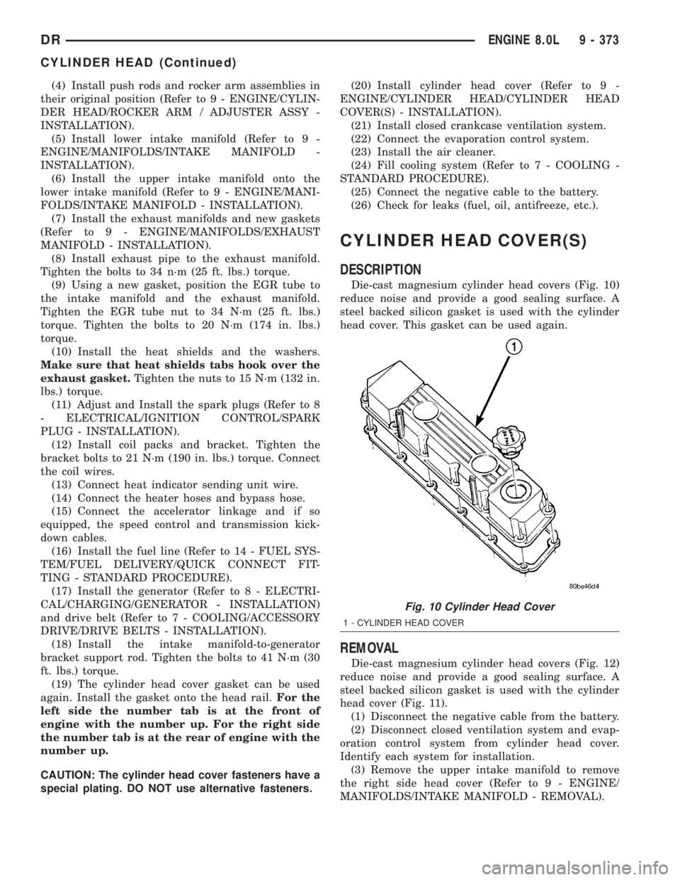
Die-cast magnesium cylinder head covers (Fig. 10)
reduce noise and provide a good sealing surface. A
steel backed silicon gasket is used with the cylinder
head cover. This gasket can be used again.
REMOVAL
Die-cast magnesium cylinder head covers (Fig. 12)
reduce noise and provide a good sealing surface. A
steel backed silicon gasket is used with the cylinder
head cover (Fig. 11).
(1) Disconnect the negative cable from the battery.
(2) Disconnect closed ventilation system and evap-
oration control system from cylinder head cover.
Identify each system for installation.
(3) Remove the upper intake manifold to remove
the right side head cover (Refer to 9 - ENGINE/
MANIFOLDS/INTAKE MANIFOLD - REMOVAL).
Fig. 10 Cylinder Head Cover
1 - CYLINDER HEAD COVER
DRENGINE 8.0L 9 - 373
CYLINDER HEAD (Continued)
Page 1626 of 2895
REMOVAL
REMOVALÐVALVE STEM SEALS
NOTE: This procedure is done with the cylinder
head installed.
(1) Disconnect the negative cable from the battery.
(2) Set engine basic timing to Top Dead Center
(TDC) and remove air cleaner.
(3) Remove cylinder head covers (Refer to 9 -
ENGINE/CYLINDER HEAD/CYLINDER HEAD
COVER(S) - REMOVAL) and spark plugs (Refer to 8
- ELECTRICAL/IGNITION CONTROL/SPARK
PLUG - REMOVAL).
(4) Using suitable socket and flex handle at crank-
shaft retaining bolt, turn engine so that the piston of
the cylinder to be worked on, is at TDC on the com-
pression stroke.
(5) Remove rocker arms (Refer to 9 - ENGINE/
CYLINDER HEAD/ROCKER ARM / ADJUSTER
ASSY - REMOVAL).
(6) With air hose attached to an adapter installed
in the spark plug hole, apply 620-689 kPa (90-100
psi) air pressure.
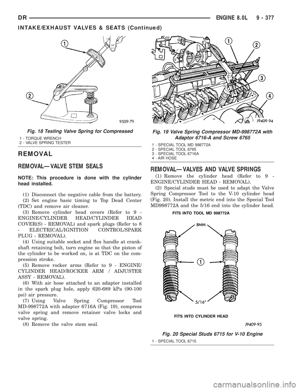
(7) Using Valve Spring Compressor Tool
MD-998772A with adapter 6716A (Fig. 19), compress
valve spring and remove retainer valve locks and
valve spring.
(8) Remove the valve stem seal.
REMOVALÐVALVES AND VALVE SPRINGS
(1) Remove the cylinder head (Refer to 9 -
ENGINE/CYLINDER HEAD - REMOVAL).
(2) Special studs must be used to adapt the Valve
Spring Compressor Tool to the V-10 cylinder head
(Fig. 20). Install the metric end into the Special Tool
MD998772A and the 5/16 end into the cylinder head.
Fig. 18 Testing Valve Spring for Compressed
1 - TORQUE WRENCH
2 - VALVE SPRING TESTER
Fig. 19 Valve Spring Compressor MD-998772A with
Adaptor 6716-A and Screw 6765
1 - SPECIAL TOOL MD 998772A
2 - SPECIAL TOOL 6765
3 - SPECIAL TOOL 6716A
4 - AIR HOSE
Fig. 20 Special Studs 6715 for V-10 Engine
1 - SPECIAL TOOL 6715
DRENGINE 8.0L 9 - 377
INTAKE/EXHAUST VALVES & SEATS (Continued)
Page 1629 of 2895
(1) Install the push rods in the same order as
removed.
(2) Install rocker arm assemblies in the same
order as removed. Tighten the rocker arm bolts to 53
N´m (40 ft. lbs.) torque.
(3) Install cylinder head cover and gasket (Refer to
9 - ENGINE/CYLINDER HEAD/CYLINDER HEAD
COVER(S) - INSTALLATION).
(4) Connect spark plug wires.
ENGINE BLOCK
CLEANING
Clean cylinder block thoroughly and check all core
hole plugs for evidence of leaking.
INSPECTION
Examine block for cracks or fractures.
The cylinder walls should be checked for out-of-
round and taper with Cylinder Bore Indicator Tool,
Special tool 6879 or equivalent. The cylinder block
should be bored and honed with new pistons and
rings fitted if:
²The cylinder bores show more than 0.127 mm
(0.005 inch) out-of-round.
²The cylinder bores show a taper of more than
0.254 mm (0.010 inch).
²The cylinder walls are badly scuffed or scored.
Boring and honing operation should be closely coor-
dinated with the fitting of pistons and rings so spec-
ified clearances may be maintained.
CAMSHAFT & BEARINGS (IN
BLOCK)
REMOVAL
REMOVALÐCAMSHAFT BEARINGS
This procedure requires that the engine is removed
from the vehicle.
(1) With engine completely disassembled, drive out
rear cam bearing core hole plug.
NOTE: It is not advisable to attempt to replace cam-
shaft bearings unless special removal and installa-
tion tools are available, such as recommended tool
8544 Camshaft Bushing Remover Installer.
(2) Using recommended tool 8544 Camshaft Bush-
ing Remover Installer, Drive out bearing shells.
REMOVALÐCAMSHAFT
(1) Remove rocker arms and push rods (Refer to 9
- ENGINE/CYLINDER HEAD/ROCKER ARM /
ADJUSTER ASSY - REMOVAL). Identify each part
so it can be installed in its original location.
NOTE: The 4 corner tappets can not be removed
without removing the cylinder heads and gaskets.
However, they can be lifted and retained for cam-
shaft removal.
(2) Remove the Bolts retaining the yoke retaining
spider. Remove the yoke retaining spider, tappet
aligning yokes and tappets.
(3) Remove upper and lower intake manifolds
(Refer to 9 - ENGINE/MANIFOLDS/INTAKE MANI-
FOLD - REMOVAL).
(4) Remove timing chain cover (Refer to 9 -
ENGINE/VALVE TIMING/TIMING BELT / CHAIN
COVER(S) - REMOVAL) and timing chain and
sprockets (Refer to 9 - ENGINE/VALVE TIMING/
TIMING BELT/CHAIN AND SPROCKETS -
REMOVAL).
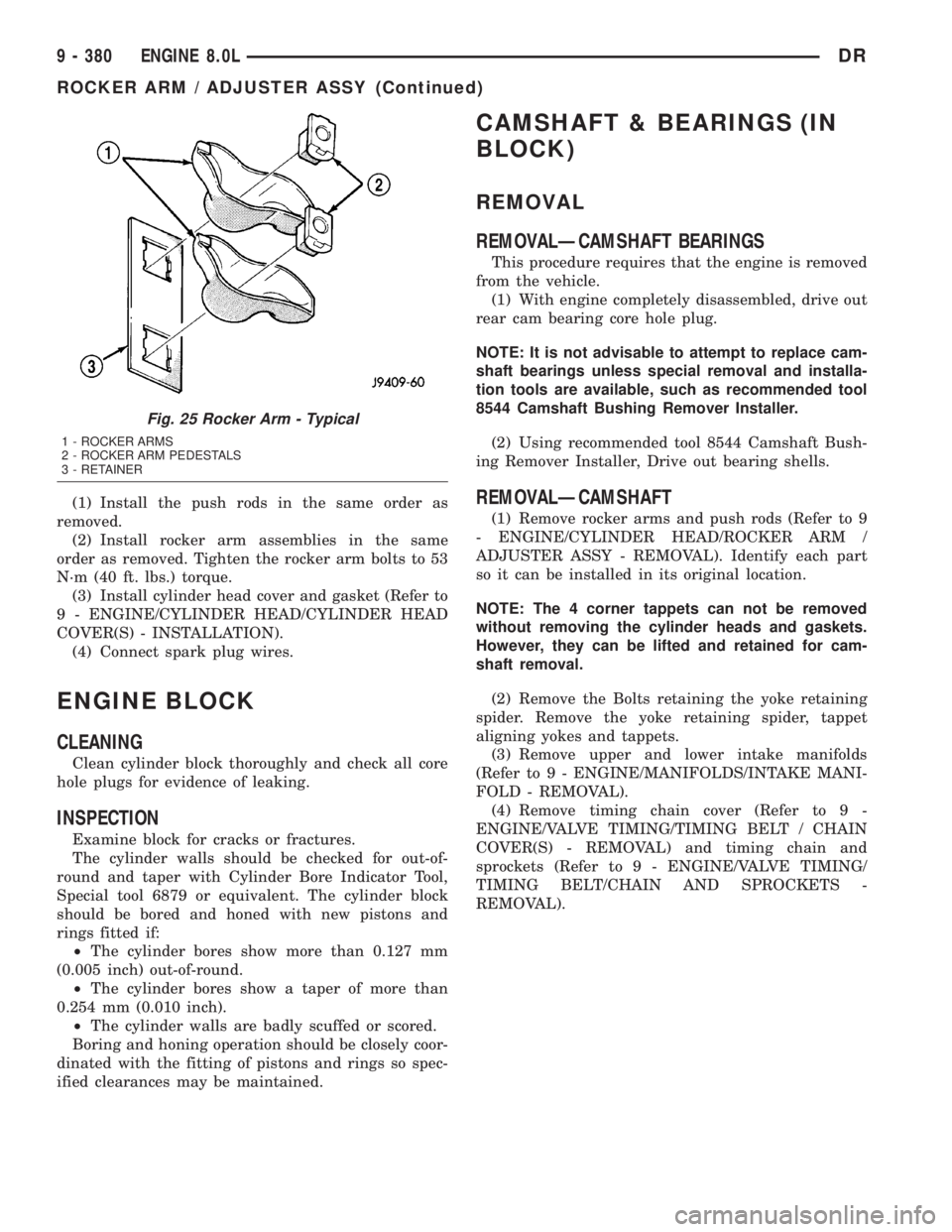
Fig. 25 Rocker Arm - Typical
1 - ROCKER ARMS
2 - ROCKER ARM PEDESTALS
3 - RETAINER
9 - 380 ENGINE 8.0LDR
ROCKER ARM / ADJUSTER ASSY (Continued)
Page 1659 of 2895
SPECIFICATIONS - TORQUE
DESCRIPTION N´m Ft. In.
Lbs. Lbs.
Adjusting StrapÐBolt 23 Ð 200
Air Heater Power SupplyÐ
Nuts14 Ð 124
Air Inlet HousingÐBolts 24 18 Ð
Cab Heater Supply/Return
LineÐNuts24 18 Ð
Exhaust ClampÐNuts 48 35 Ð
Exhaust Manifold to Cylinder
HeadÐBolts
(Diesel Engine) 43 32 Ð
Exhaust Manifold to Cylinder
HeadÐBolts
(5.9L) 31 23 Ð
Exhaust Manifold to Cylinder
HeadÐBolts
(8.0L) 22 Ð 195
Exhaust Pipe to ManifoldÐ
Bolts31 23 Ð
Generator MountingÐBolts 41 30 Ð
Charge Air Cooler
MountingÐBolts2Ð17
Charge Air Cooler DuctÐ
Nuts11 Ð 9 5
Heat ShieldÐNuts and Bolts 11 Ð 95
Turbocharger flange studs 24 18 Ð
Turbocharger MountingÐ
Nuts43 32 Ð
Turbocharger Oil Drain
TubeÐBolts24 18 Ð
Turbocharger Oil Supply
LineÐFitting24 18 Ð
Turbocharger V-Band
ClampÐNut9Ð75
Turbocharger Oil Supply
fitting (at Turbocharger)36 27 Ð
Turbocharger Oil Supply
fitting (at lube filter head)24 18 Ð
Turbocharger Drain Hose
Clamps8Ð71
SPECIAL TOOLS
CATALYTIC CONVERTER
DESCRIPTION - CATALYTIC CONVERTER
WARNING: THE NORMAL OPERATING TEMPERA-
TURE OF THE EXHAUST SYSTEM IS VERY HIGH.
THEREFORE, NEVER WORK AROUND OR ATTEMPT
TO SERVICE ANY PART OF THE EXHAUST SYSTEM
UNTIL IT IS COOLED. SPECIAL CARE SHOULD BE
TAKEN WHEN WORKING NEAR THE CATALYTIC
CONVERTER. THE TEMPERATURE OF THE CON-
VERTER RISES TO A HIGH LEVEL AFTER A SHORT
PERIOD OF ENGINE OPERATION TIME.
CAUTION: DO NOT remove spark plug wires from
plugs or by any other means short out cylinders.
Failure of the catalytic converter can occur due to a
temperature increase caused by unburned fuel
passing through the converter.
The stainless steel catalytic converter body is
designed to last the life of the vehicle. Excessive heat
can result in bulging or other distortion, but exces-
sive heat will not be the fault of the converter. If
unburned fuel enters the converter, overheating may
occur. If a converter is heat-damaged, correct the
cause of the damage at the same time the converter
is replaced. Also, inspect all other components of the
exhaust system for heat damage.
Unleaded gasoline must be used to avoid con-
taminating the catalyst core.
50 State emission vehicles incorporate two mini
catalytic converters located after the exhaust mani-
folds and before the inline catalytic converter.
OPERATION
The catalytic converter captures and burns any
unburned fuel mixture exiting the combustion cham-
bers during the exhaust stroke of the engine. This
process aids in reducing emissions output.
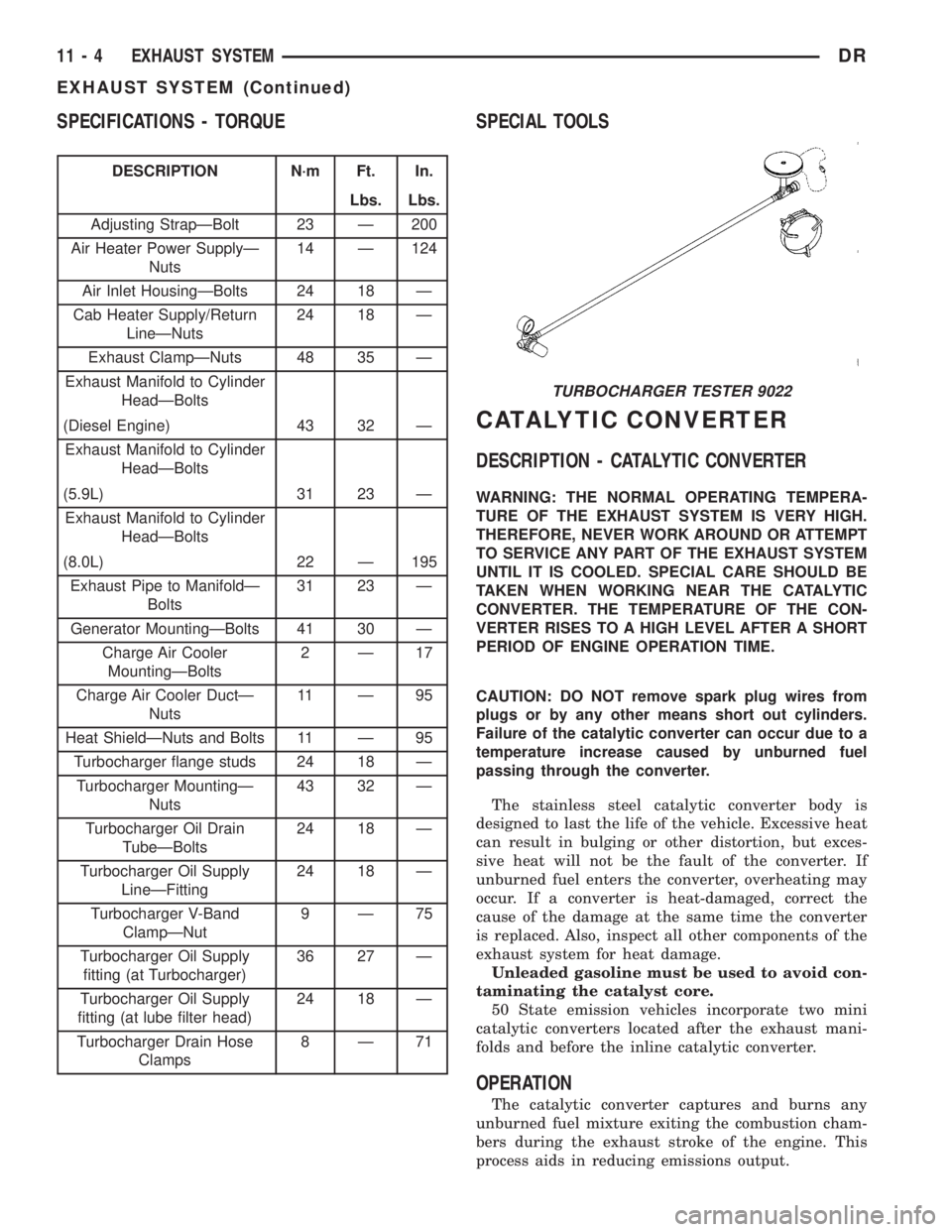
TURBOCHARGER TESTER 9022
11 - 4 EXHAUST SYSTEMDR
EXHAUST SYSTEM (Continued)
Page 1712 of 2895
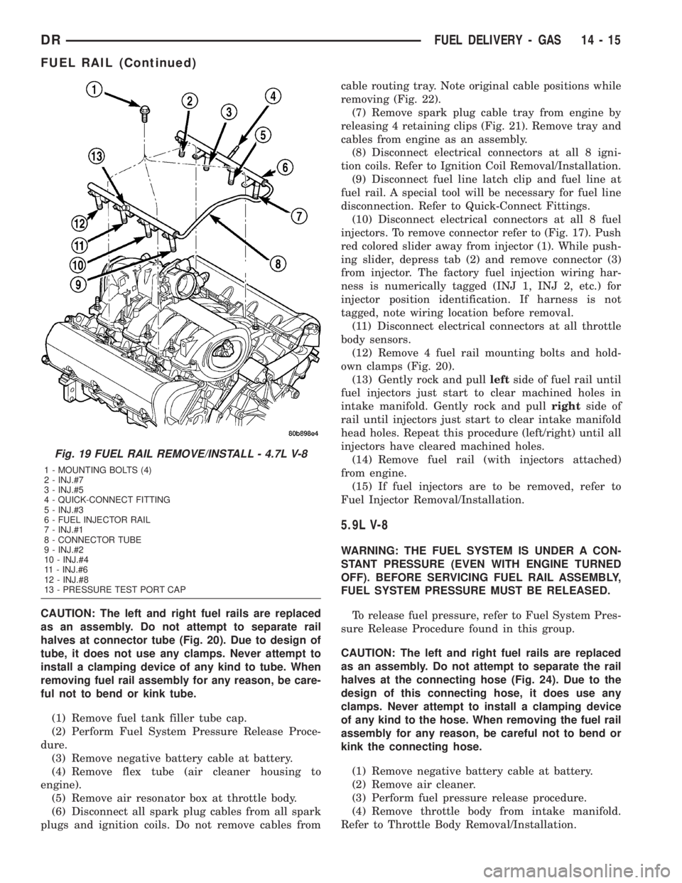
CAUTION: The left and right fuel rails are replaced
as an assembly. Do not attempt to separate rail
halves at connector tube (Fig. 20). Due to design of
tube, it does not use any clamps. Never attempt to
install a clamping device of any kind to tube. When
removing fuel rail assembly for any reason, be care-
ful not to bend or kink tube.
(1) Remove fuel tank filler tube cap.
(2) Perform Fuel System Pressure Release Proce-
dure.
(3) Remove negative battery cable at battery.
(4) Remove flex tube (air cleaner housing to
engine).
(5) Remove air resonator box at throttle body.
(6) Disconnect all spark plug cables from all spark
plugs and ignition coils. Do not remove cables fromcable routing tray. Note original cable positions while
removing (Fig. 22).
(7) Remove spark plug cable tray from engine by
releasing 4 retaining clips (Fig. 21). Remove tray and
cables from engine as an assembly.
(8) Disconnect electrical connectors at all 8 igni-
tion coils. Refer to Ignition Coil Removal/Installation.
(9) Disconnect fuel line latch clip and fuel line at
fuel rail. A special tool will be necessary for fuel line
disconnection. Refer to Quick-Connect Fittings.
(10) Disconnect electrical connectors at all 8 fuel
injectors. To remove connector refer to (Fig. 17). Push
red colored slider away from injector (1). While push-
ing slider, depress tab (2) and remove connector (3)
from injector. The factory fuel injection wiring har-
ness is numerically tagged (INJ 1, INJ 2, etc.) for
injector position identification. If harness is not
tagged, note wiring location before removal.
(11) Disconnect electrical connectors at all throttle
body sensors.
(12) Remove 4 fuel rail mounting bolts and hold-
own clamps (Fig. 20).
(13) Gently rock and pullleftside of fuel rail until
fuel injectors just start to clear machined holes in
intake manifold. Gently rock and pullrightside of
rail until injectors just start to clear intake manifold
head holes. Repeat this procedure (left/right) until all
injectors have cleared machined holes.
(14) Remove fuel rail (with injectors attached)
from engine.
(15) If fuel injectors are to be removed, refer to
Fuel Injector Removal/Installation.
5.9L V-8
WARNING: THE FUEL SYSTEM IS UNDER A CON-
STANT PRESSURE (EVEN WITH ENGINE TURNED
OFF). BEFORE SERVICING FUEL RAIL ASSEMBLY,
FUEL SYSTEM PRESSURE MUST BE RELEASED.
To release fuel pressure, refer to Fuel System Pres-
sure Release Procedure found in this group.
CAUTION: The left and right fuel rails are replaced
as an assembly. Do not attempt to separate the rail
halves at the connecting hose (Fig. 24). Due to the
design of this connecting hose, it does use any
clamps. Never attempt to install a clamping device
of any kind to the hose. When removing the fuel rail
assembly for any reason, be careful not to bend or
kink the connecting hose.
(1) Remove negative battery cable at battery.
(2) Remove air cleaner.
(3) Perform fuel pressure release procedure.
(4) Remove throttle body from intake manifold.
Refer to Throttle Body Removal/Installation.
Fig. 19 FUEL RAIL REMOVE/INSTALL - 4.7L V-8
1 - MOUNTING BOLTS (4)
2 - INJ.#7
3 - INJ.#5
4 - QUICK-CONNECT FITTING
5 - INJ.#3
6 - FUEL INJECTOR RAIL
7 - INJ.#1
8 - CONNECTOR TUBE
9 - INJ.#2
10 - INJ.#4
11 - INJ.#6
12 - INJ.#8
13 - PRESSURE TEST PORT CAP
DRFUEL DELIVERY - GAS 14 - 15
FUEL RAIL (Continued)
Page 1716 of 2895
(11) Connect necessary vacuum lines to throttle
body.
(12) Install air resonator mounting bracket near
front of throttle body (2 bolts).
(13) Connect fuel line latch clip and fuel line to
fuel rail. Refer to Quick-Connect Fittings.
(14) Install air box to throttle body.
(15) Install air duct to air box.
(16) Connect battery cable to battery.
(17) Start engine and check for leaks.
4.7L V-8
(1) If fuel injectors are to be installed, refer to Fuel
Injector Removal/Installation.
(2) Clean out fuel injector machined bores in
intake manifold.
(3) Apply a small amount of engine oil to each fuel
injector o-ring. This will help in fuel rail installation.
(4) Position fuel rail/fuel injector assembly to
machined injector openings in cylinder head.
(5) Guide each injector into cylinder head. Be care-
ful not to tear injector o-rings.
(6) Pushrightside of fuel rail down until fuel
injectors have bottomed on cylinder head shoulder.
Pushleftfuel rail down until injectors have bot-
tomed on cylinder head shoulder.
(7) Install 4 fuel rail mounting bolts and tighten.
Refer to torque specifications.
(8) Install 8 ignition coils. Refer to Ignition Coil
Removal/Installation.
(9) Connect electrical connectors to throttle body.
(10) Connect electrical connectors at all fuel injec-
tors. To install connector, refer to (Fig. 17). Push con-
nector onto injector (1) and then push and lock red
colored slider (2). Verify connector is locked to injec-
tor by lightly tugging on connector.
(11) Connect necessary vacuum lines to throttle
body.
(12) Install air resonator mounting bracket near
front of throttle body (2 bolts).
(13) Connect fuel line latch clip and fuel line to
fuel rail. Refer to Quick-Connect Fittings.
(14) Install air box to throttle body.
(15) Install air duct to air box.
(16) Connect battery cable to battery.
(17) Start engine and check for leaks.
5.7L V-8
(1) If fuel injectors are to be installed, refer to Fuel
Injector Removal/Installation.
(2) Clean out fuel injector machined bores in
intake manifold.
(3) Apply a small amount of engine oil to each fuel
injector o-ring. This will help in fuel rail installation.
(4) Position fuel rail/fuel injector assembly to
machined injector openings in intake manifold.(5) Guide each injector into intake manifold. Be
careful not to tear injector o-rings.
(6) Pushrightside of fuel rail down until fuel
injectors have bottomed on shoulders. Pushleftfuel
rail down until injectors have bottomed on shoulders.
(7) Install 4 fuel rail holdown clamps and 4 mount-
ing bolts. Refer to Torque Specifications.
(8) Position spark plug cable tray and cable assem-
bly to intake manifold. Snap 4 cable tray retaining
clips into intake manifold.
(9) Install all cables to spark plugs and ignition
coils.
(10) Connect electrical connector to throttle body.
(11) Install electrical connectors to all 8 ignition
coils. Refer to Ignition Coil Removal/Installation.
(12) Connect electrical connector to throttle body.
(13) Connect electrical connectors at all fuel injec-
tors. To install connector, refer to (Fig. 17). Push con-
nector onto injector (1) and then push and lock red
colored slider (2). Verify connector is locked to injec-
tor by lightly tugging on connector.
(14) Connect fuel line latch clip and fuel line to
fuel rail. Refer to Quick-Connect Fittings.
(15) Install air resonator to throttle body (2 bolts).
(16) Install flexible air duct to air box.
(17) Connect battery cable to battery.
(18) Start engine and check for leaks.
5.9L V-8
(1) If fuel injectors are to be installed, refer to Fuel
Injector Removal/Installation.
(2) Apply a small amount of engine oil to each fuel
injector o-ring. This will help in fuel rail installation.
(3) Clean out fuel injector machined bores in
intake manifold.
(4) Position fuel rail/fuel injector assembly to injec-
tor openings on intake manifold.
(5) Guide each injector into intake manifold. Be
careful not to tear injector o-ring.
(6) Push therightfuel rail down until fuel injec-
tors have bottomed on injector shoulder. Push the
leftfuel rail down until fuel injectors have bottomed
on injector shoulder.
(7) Install fuel rail mounting bolts. Refer to Torque
Specifications.
(8) Connect electrical connector to intake manifold
air temperature sensor.
(9) Connect electrical connectors at all fuel injec-
tors. To install connector, refer to (Fig. 17). Push con-
nector onto injector (1) and then push and lock red
colored slider (2). Verify connector is locked to injec-
tor by lightly tugging on connector.
(10) Install fuel tube (line) at side of fuel rail.
Refer to Quick-Connect Fittings for procedures.
(11) Install air cleaner resonator to throttle body.
(12) Connect battery cable to battery.
DRFUEL DELIVERY - GAS 14 - 19
FUEL RAIL (Continued)
Page 2837 of 2895
²Upstream O2S VoltsÐ A live reading of the
Oxygen Sensor to indicate its performance. For
example, stuck lean, stuck rich, etc.
²SCW Time in Window (Similar Conditions
Window Time in Window)Ð A timer used by the
PCM that indicates that, after all Similar Conditions
have been met, if there has been enough good engine
running time in the SCW without failure detected.
This timer is used to increment a Good Trip.
²Fuel System Good Trip CounterÐATrip
Counter used to turn OFF the MIL for Fuel System
DTCs. To increment a Fuel System Good Trip, the
engine must be in the Similar Conditions Window,
Adaptive Memory Factor must be less than cali-
brated threshold and the Adaptive Memory Factor
must stay below that threshold for a calibrated
amount of time.
²Test Done This TripÐ Indicates that the
monitor has already been run and completed during
the current trip.
MISFIRE
²Same Misfire Warm-Up StateÐ Indicates if
the misfire occurred when the engine was warmed up
(above 160É F).
²In Similar Misfire WindowÐ An indicator
that 'Absolute MAP When Misfire Occurred' and
'RPM When Misfire Occurred' are all in the same
range when the failure occurred. Indicated by switch-
ing from 'NO' to 'YES'.
²Absolute MAP When Misfire OccurredÐ
The stored MAP reading at the time of failure.
Informs the user at what engine load the failure
occurred.
²Absolute MAPÐ A live reading of engine load
to aid the user in accessing the Similar Conditions
Window.
²RPM When Misfire OccurredÐ The stored
RPM reading at the time of failure. Informs the user
at what engine RPM the failure occurred.
²Engine RPMÐ A live reading of engine RPM
to aid the user in accessing the Similar Conditions
Window.
²Adaptive Memory FactorÐ The PCM utilizes
both Short Term Compensation and Long Term Adap-
tive to calculate the Adaptive Memory Factor for
total fuel correction.
²200 Rev CounterÐ Counts 0±100 720 degree
cycles.
²SCW Cat 200 Rev CounterÐ Counts when in
similar conditions.
²SCW FTP 1000 Rev CounterÐ Counts 0±4
when in similar conditions.
²Misfire Good Trip CounterÐ Counts up to
three to turn OFF the MIL.
²Misfire DataÐ Data collected during test.²Test Done This TripÐ Indicates YES when the
test is done.
OPERATION - NON-MONITORED CIRCUITS
The PCM does not monitor the following circuits,
systems and conditions that could have malfunctions
causing driveability problems. The PCM might not
store diagnostic trouble codes for these conditions.
However, problems with these systems may cause the
PCM to store diagnostic trouble codes for other sys-
tems or components.EXAMPLE:a fuel pressure
problem will not register a fault directly, but could
cause a rich/lean condition or misfire. This could
cause the PCM to store an oxygen sensor or misfire
diagnostic trouble code
FUEL PRESSURE
The fuel pressure regulator controls fuel system
pressure. The PCM cannot detect a clogged fuel
pump inlet filter, clogged in-line fuel filter, or a
pinched fuel supply or return line. However, these
could result in a rich or lean condition causing the
PCM to store an oxygen sensor or fuel system diag-
nostic trouble code.
SECONDARY IGNITION CIRCUIT
The PCM cannot detect an inoperative ignition coil,
fouled or worn spark plugs, ignition cross firing, or
open spark plug cables.
CYLINDER COMPRESSION
The PCM cannot detect uneven, low, or high engine
cylinder compression.
EXHAUST SYSTEM
The PCM cannot detect a plugged, restricted or
leaking exhaust system, although it may set a fuel
system fault.
FUEL INJECTOR MECHANICAL MALFUNCTIONS
The PCM cannot determine if a fuel injector is
clogged, the needle is sticking or if the wrong injector
is installed. However, these could result in a rich or
lean condition causing the PCM to store a diagnostic
trouble code for either misfire, an oxygen sensor, or
the fuel system.
EXCESSIVE OIL CONSUMPTION
Although the PCM monitors engine exhaust oxygen
content when the system is in closed loop, it cannot
determine excessive oil consumption.
THROTTLE BODY AIR FLOW
The PCM cannot detect a clogged or restricted air
cleaner inlet or filter element.
25 - 8 EMISSIONS CONTROLDR
EMISSIONS CONTROL (Continued)
Page 2880 of 2895
PLANETARY GEARTRAIN/OUTPUT SHAFT
- INSPECTION................21-245,21-422
PLANETARY GEARTRAIN/OUTPUT SHAFT
- OPERATION.................21-243,21-420
PLASTIC BODY PANEL REPAIR -
STANDARD PROCEDURE................23-3
PLATE - DESCRIPTION, BODY CODE....Intro.-4
PLATE - DESCRIPTION, ENGINE DATA....9-297
PLATE - INSTALLATION, FLEX . . 9-137,9-205,9-47
PLATE - INSTALLATION, FRONT SKID.....13-24
PLATE - INSTALLATION, SUPPORT........5-29
PLATE - INSTALLATION, TRANSFER
CASE SKID.........................13-26
PLATE - REMOVAL, FLEX.....9-137,9-205,9-47
PLATE - REMOVAL, FRONT SKID........13-24
PLATE - REMOVAL, SUPPORT...........5-29
PLATE - REMOVAL, TRANSFER CASE
SKID..............................13-26
PLATE LAMP - INSTALLATION, LICENSE . . 8L-16
PLATE LAMP - REMOVAL, LICENSE......8L-16
PLATE LAMP UNIT - INSTALLATION,
LICENSE...........................8L-16
PLATE LAMP UNIT - REMOVAL, LICENSE . . 8L-16
PLATES - INSTALLATION, EXTERIOR
NAME.............................23-38
PLATES - REMOVAL, EXTERIOR NAME....23-38
PLUG - DESCRIPTION, SPARK...........8I-27
PLUG - INSTALLATION, CAMSHAFT
CORE HOLE.........................9-201
PLUG - REMOVAL, CAMSHAFT CORE
HOLE..............................9-200
PLUG - REMOVAL, SPARK..............8I-30
PLUG CABLE - DESCRIPTION, SPARK.....8I-33
PLUG CABLE - INSTALLATION, SPARK....8I-35
PLUG CABLE - OPERATION, SPARK.......8I-33
PLUG CABLE - REMOVAL, SPARK........8I-34
PLUG CABLE ORDER, 8.0L V-10 ENGINE
- SPARK .............................8I-5
PLUG CABLE RESISTANCE,
SPECIFICATIONS - SPARK...............8I-5
PLUG CABLES - DIAGNOSIS AND
TESTING, SPARK.....................8I-33
PLUG CONDITIONS - DIAGNOSIS AND
TESTING, SPARK.....................8I-27
PLUGS - INSTALLATION, CORE..........9-130
PLUGS - REMOVAL, CORE.............9-129
PLUGS, SPECIFICATIONS - SPARK........8I-5
PLUMBING - CLEANING, CHARGE AIR
COOLER............................11-16
PLUMBING - DESCRIPTION, CHARGE
AIR COOLER........................11-15
PLUMBING - INSPECTION, CHARGE AIR
COOLER............................11-16
PLUMBING - INSTALLATION, CHARGE
AIR COOLER........................11-16
PLUMBING - OPERATION, CHARGE AIR
COOLER............................11-15
PLUMBING - REMOVAL, CHARGE AIR
COOLER............................11-15
PLY TIRES - DESCRIPTION, RADIAL.......22-6
POLISHING - DESCRIPTION, FINESSE
SANDING/BUFFING...................23-75
PORT - DESCRIPTION, REFRIGERANT
SYSTEM SERVICE.....................24-1
PORT - OPERATION, REFRIGERANT
SYSTEM SERVICE.....................24-2
POSITION SENSOR - DESCRIPTION.....21-618,
21-654
POSITION SENSOR - DESCRIPTION,
ACCELERATOR PEDAL.................14-25
POSITION SENSOR - DESCRIPTION,
CAMSHAFT.........................14-82
POSITION SENSOR - DESCRIPTION,
CAMSHAFT...........................8I-8
POSITION SENSOR - DESCRIPTION,
CRANKSHAFT..................14-26,14-83
POSITION SENSOR - DESCRIPTION,
THROTTLE..........................14-52
POSITION SENSOR - INSTALLATION
....21-619,
21-654
POSITION SENSOR - INSTALLATION,
ACCELERATOR PEDAL
.................14-25
POSITION SENSOR - INSTALLATION,
CAMSHAFT
.........................14-83
POSITION SENSOR - INSTALLATION,
CAMSHAFT
..........................8I-14
POSITION SENSOR - INSTALLATION,
CRANKSHAFT
..................14-30,14-84POSITION SENSOR - INSTALLATION,
THROTTLE..........................14-54
POSITION SENSOR - OPERATION . 21-619,21-654
POSITION SENSOR - OPERATION,
ACCELERATOR PEDAL.................14-25
POSITION SENSOR - OPERATION,
CAMSHAFT.........................14-82
POSITION SENSOR - OPERATION,
CAMSHAFT...........................8I-8
POSITION SENSOR - OPERATION,
CRANKSHAFT..................14-26,14-83
POSITION SENSOR - OPERATION,
THROTTLE..........................14-52
POSITION SENSOR - REMOVAL . . 21-619,21-654
POSITION SENSOR - REMOVAL,
ACCELERATOR PEDAL.................14-25
POSITION SENSOR - REMOVAL,
CAMSHAFT.........................14-83
POSITION SENSOR - REMOVAL,
CAMSHAFT..........................8I-11
POSITION SENSOR - REMOVAL,
CRANKSHAFT..................14-29,14-84
POSITION SENSOR - REMOVAL,
THROTTLE..........................14-53
POSITION SWITCH - DESCRIPTION,
CLUTCH PEDAL.......................6-14
POSITION SWITCH - DIAGNOSIS AND
TESTING, CLUTCH PEDAL...............6-14
POSITION SWITCH - OPERATION,
CLUTCH PEDAL.......................6-14
POTENTIAL - STANDARD PROCEDURE,
TESTING OF VOLTAGE..............8W-01-9
POWER - INSTALLATION, WINDOW
REGULATOR...................23-25,23-34
POWER - REMOVAL, WINDOW
REGULATOR...................23-25,23-34
POWER BRAKE BOOSTER -
DESCRIPTION........................5-25
POWER BRAKE BOOSTER -
INSTALLATION........................5-25
POWER BRAKE BOOSTER - OPERATION . . . 5-25
POWER BRAKE BOOSTER - REMOVAL.....5-25
POWER DISTRIBUTION - DESCRIPTION . 8W-97-1
POWER DISTRIBUTION - OPERATION . . 8W-97-1
POWER DISTRIBUTION SYSTEMS,
SPECIAL TOOLS...................8W-97-2
POWER GROUNDS - DESCRIPTION......8E-10
POWER LOCK SWITCH - DIAGNOSIS
AND TESTING........................8N-4
POWER LOCK SWITCH - INSTALLATION . . . 8N-4
POWER LOCK SWITCH - REMOVAL.......8N-4
POWER LOCKS - DESCRIPTION..........8N-1
POWER LOCKS - DIAGNOSIS AND
TESTING............................8N-3
POWER LOCKS - OPERATION............8N-2
POWER MIRROR SWITCH - DIAGNOSIS
AND TESTING.......................8N-13
POWER MIRROR SWITCH - REMOVAL
. . . 8N-13
POWER MIRRORS - DESCRIPTION
......8N-11
POWER MIRRORS - DIAGNOSIS AND
TESTING
...........................8N-11
POWER MIRRORS - OPERATION
........8N-11
POWER MODULE - DESCRIPTION,
INTEGRATED
......................8W-97-3
POWER MODULE - INSTALLATION,
INTEGRATED
......................8W-97-4
POWER MODULE - OPERATION,
INTEGRATED
......................8W-97-3
POWER MODULE - REMOVAL,
INTEGRATED
......................8W-97-3
POWER OUTLET - DESCRIPTION
......8W-97-7
POWER OUTLET - DIAGNOSIS AND
TESTING
.........................8W-97-7
POWER OUTLET - INSTALLATION
.....8W-97-7
POWER OUTLET - OPERATION
........8W-97-7
POWER OUTLET - REMOVAL
.........8W-97-7
POWER SEAT SYSTEM - DIAGNOSIS
AND TESTING
.......................8N-14
POWER SEAT TRACK - DESCRIPTION
....8N-18
POWER SEAT TRACK - DIAGNOSIS AND
TESTING
...........................8N-18
POWER SEAT TRACK - INSTALLATION
....8N-19
POWER SEAT TRACK - OPERATION
......8N-18
POWER SEAT TRACK - REMOVAL
.......8N-19
POWER SEATS - DESCRIPTION
.........8N-14
POWER SEATS - OPERATION
...........8N-14POWER STEERING FLOW AND
PRESSURE - DIAGNOSIS AND
TESTING............................19-4
POWER STEERING FLUID -
DESCRIPTION.........................0-3
POWER STEERING FLUID LEVEL
CHECKING - STANDARD PROCEDURE....19-42
POWER STEERING GEAR, SPECIAL
TOOLS.............................19-22
POWER STEERING GEAR,
SPECIFICATIONS.....................19-21
POWER STEERING PRESSURE SWITCH -
DESCRIPTION.......................19-45
POWER STEERING PRESSURE SWITCH -
OPERATION.........................19-45
POWER STEERING PUMP - INITIAL
OPERATION - STANDARD PROCEDURE . . . 19-39
POWER STEERING SYSTEM -
DIAGNOSIS AND TESTING..............19-2
POWER STEERING SYSTEM -
STANDARD PROCEDURE, FLUSHING.....19-39
POWER WINDOWS - DESCRIPTION......8N-21
POWER WINDOWS - DIAGNOSIS AND
TESTING...........................8N-21
POWER WINDOWS - OPERATION........8N-21
POWERING SEVERAL LOADS -
STANDARD PROCEDURE, TESTING
FOR A SHORT TO GROUND ON FUSES . 8W-01-10
PRE-ALIGNMENT INSPECTION -
DIAGNOSIS AND TESTING...............2-2
PRECAUTIONS - CAUTION,
REFRIGERANT HOSES/LINES/TUBES......24-33
PRECAUTIONS AND WARNINGS,
WARNING - SAFETY.....................23-1
PRECAUTIONS, STANDARD PROCEDURE
- SAFETY............................8L-7
PRECAUTIONS, WARNING -
WINDSHIELD SAFETY.................23-88
PREFERENCES - STANDARD
PROCEDURE, RKE TRANSMITTER
CUSTOMER..........................8N-9
PRELIMINARY - DIAGNOSIS AND
TESTING..............21-139,21-320,21-491
PRELIMINARY CHECKS - DIAGNOSIS
AND TESTING........................7-10
PREPARATION - STANDARD
PROCEDURE, ENGINE GASKET
SURFACE............................9-10
PRESSURE - DIAGNOSIS AND TESTING,
CHECKING ENGINE OIL.......9-150,9-214,9-64
PRESSURE - DIAGNOSIS AND TESTING,
CYLINDER COMPRESSION . . . 9-182,9-231,9-359,
9-8,9-92
PRESSURE - DIAGNOSIS AND TESTING,
ENGINE OIL...............9-269,9-338,9-396
PRESSURE - DIAGNOSIS AND TESTING,
POWER STEERING FLOW...............19-4
PRESSURE - DIAGNOSIS AND TESTING,
TURBOCHARGER BOOST...............11-10
PRESSURE BLEEDING - STANDARD
PROCEDURE..........................5-5
PRESSURE CAP - DESCRIPTION,
RADIATOR...........................7-60
PRESSURE CAP - OPERATION,
RADIATOR...........................7-61
PRESSURE, DIESEL - FUEL SYSTEM
.....14-60
PRESSURE FOR HIGH SPEEDS -
DESCRIPTION, TIRE
...................22-6
PRESSURE GAUGE - DESCRIPTION, OIL
. . 8J-32
PRESSURE GAUGE - OPERATION, OIL
....8J-32
PRESSURE GAUGES - DIAGNOSIS AND
TESTING
............................22-7
PRESSURE HOSE - INSTALLATION
. . 19-43,19-44
PRESSURE HOSE - REMOVAL
.....19-43,19-44
PRESSURE LEAKAGE - DIAGNOSIS AND
TESTING, CYLINDER COMBUSTION
. 9-182,9-231,
9-359,9-8,9-92
PRESSURE LIMITING VALVE -
DESCRIPTION, FUEL
..................14-72
PRESSURE LIMITING VALVE -
INSTALLATION, FUEL
.................14-73
PRESSURE LIMITING VALVE -
OPERATION, FUEL
....................14-72
PRESSURE LIMITING VALVE - REMOVAL,
FUEL
..............................14-72
PRESSURE (LP) SENSOR -
DESCRIPTION, LINE
.................21-559
DRINDEX 25
Description Group-Page Description Group-Page Description Group-Page