2003 DODGE RAM brake fluid
[x] Cancel search: brake fluidPage 2215 of 2895
ADJUSTMENTS - BRAKE TRANSMISSION
SHIFT INTERLOCK
Correct cable adjustment is important to proper
interlock operation. The gearshift cable must be cor-
rectly adjusted in order to shift out of PARK.
ADJUSTMENT PROCEDURE
(1) Remove the steering column trim as necessary
for access to the brake transmission shift interlock.
(2) Shift the transmission into the PARK position.
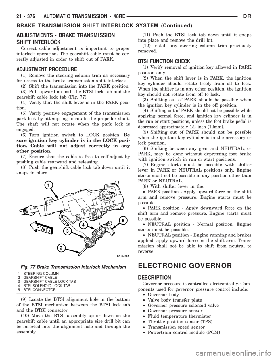
(3) Pull upward on both the BTSI lock tab and the
gearshift cable lock tab (Fig. 77).
(4) Verify that the shift lever is in the PARK posi-
tion.
(5) Verify positive engagement of the transmission
park lock by attempting to rotate the propeller shaft.
The shaft will not rotate when the park lock is
engaged.
(6) Turn ignition switch to LOCK position.Be
sure ignition key cylinder is in the LOCK posi-
tion. Cable will not adjust correctly in any
other position.
(7) Ensure that the cable is free to self-adjust by
pushing cable rearward and releasing.
(8) Push the gearshift cable lock tab down until it
snaps in place.
(9) Locate the BTSI alignment hole in the bottom
of the BTSI mechanism between the BTSI lock tab
and the BTSI connector.
(10) Move the BTSI assembly up or down on the
gearshift cable until an appropriate size drill bit can
be inserted into the alignment hole and through the
assembly.(11) Push the BTSI lock tab down until it snaps
into place and remove the drill bit.
(12) Install any steering column trim previously
removed.
BTSI FUNCTION CHECK
(1) Verify removal of ignition key allowed in PARK
position only.
(2) When the shift lever is in PARK, the ignition
key cylinder should rotate freely from off to lock.
When the shifter is in any other position, the ignition
key should not rotate from off to lock.
(3) Shifting out of PARK should be possible when
the ignition key cylinder is in the off position.
(4)
Shifting out of PARK should not be possible while
applying normal force, and ignition key cylinder is in
the run or start positions, unless the foot brake pedal is
depressed approximately 1/2 inch (12mm).
(5) Shifting out of PARK should not be possible
when the ignition key cylinder is in the accessory or
lock position.
(6) Shifting between any gear and NEUTRAL, or
PARK, may be done without depressing foot brake
with ignition switch in run or start positions.
(7) Engine starts must be possible with shifter
lever in PARK or NEUTRAL positions only. Engine
starts must not be possible in any position other than
PARK or NEUTRAL.
(8) With shifter lever in the:
²PARK position - Apply upward force on the shift
arm and remove pressure. Engine starts must be
possible.
²PARK position - Apply downward force on the
shift arm and remove pressure. Engine starts must
be possible.
²NEUTRAL position - Normal position. Engine
starts must be possible.
²NEUTRAL position - Engine running and brakes
applied, apply upward force on the shift arm. Trans-
mission shall not be able to shift from neutral to
reverse.
ELECTRONIC GOVERNOR
DESCRIPTION
Governor pressure is controlled electronically. Com-
ponents used for governor pressure control include:
²Governor body
²Valve body transfer plate
²Governor pressure solenoid valve
²Governor pressure sensor
²Fluid temperature thermistor
²Throttle position sensor (TPS)
²Transmission speed sensor
²Powertrain control module (PCM)
Fig. 77 Brake Transmission Interlock Mechanism
1 - STEERING COLUMN
2 - GEARSHIFT CABLE
3 - GEARSHIFT CABLE LOCK TAB
4 - BTSI SOLENOID LOCK TAB
5 - BTSI CONNECTOR
21 - 376 AUTOMATIC TRANSMISSION - 48REDR
BRAKE TRANSMISSION SHIFT INTERLOCK SYSTEM (Continued)
Page 2221 of 2895
vehicle if necessary to bring fluid temperature up to
normal hot operating temperature of 82ÉC (180ÉF).
(2) Position vehicle on level surface.
(3) Start and run engine at curb idle speed.
(4) Apply parking brakes.
(5) Shift transmission momentarily into all gear
ranges. Then shift transmission back to NEUTRAL.
(6) Clean top of filler tube and dipstick to keep
dirt from entering tube.
(7) Remove dipstick (Fig. 89) and check fluid level
as follows:
(a) Correct acceptable level is in crosshatch area.
(b) Correct maximum level is to MAX arrow
mark.
(c) Incorrect level is at or below MIN line.
(d) If fluid is low, add only enough MopartAT F
+4, type 9602, to restore correct level. Do not over-
fill.
PROCEDURE TWO
(1) Start engine and apply parking brake.
(2) Shift the transmission into DRIVE for approxi-
mately 2 seconds.
(3) Shift the transmission into REVERSE for
approximately 2 seconds.
(4) Shift the transmission into PARK.
(5) Hook up DRBtscan tool and select engine.(6) Select sensors.
(7) Read the transmission temperature value.
(8) Compare the fluid temperature value with the
chart.
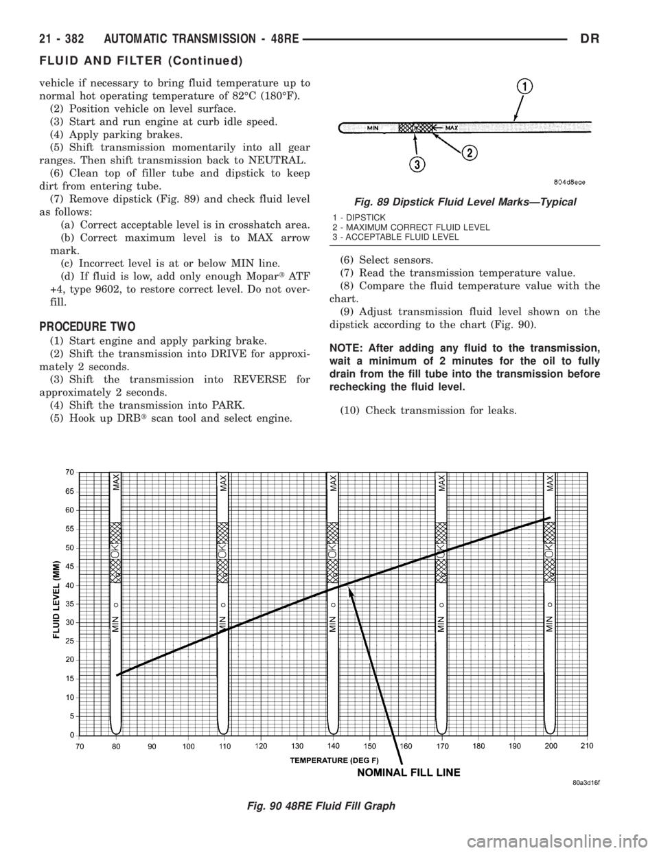
(9) Adjust transmission fluid level shown on the
dipstick according to the chart (Fig. 90).
NOTE: After adding any fluid to the transmission,
wait a minimum of 2 minutes for the oil to fully
drain from the fill tube into the transmission before
rechecking the fluid level.
(10) Check transmission for leaks.
Fig. 90 48RE Fluid Fill Graph
Fig. 89 Dipstick Fluid Level MarksÐTypical
1 - DIPSTICK
2 - MAXIMUM CORRECT FLUID LEVEL
3 - ACCEPTABLE FLUID LEVEL
21 - 382 AUTOMATIC TRANSMISSION - 48REDR
FLUID AND FILTER (Continued)
Page 2222 of 2895
STANDARD PROCEDURE - FLUID AND FILTER
REPLACEMENT
For proper service intervals (Refer to LUBRICA-
TION & MAINTENANCE/MAINTENANCE SCHED-
ULES - DESCRIPTION). The service fluid fill after a
filter change is approximately 3.8 liters (4.0 quarts).
REMOVAL
(1) Hoist and support vehicle on safety stands.
(2) Place a large diameter shallow drain pan
beneath the transmission pan.
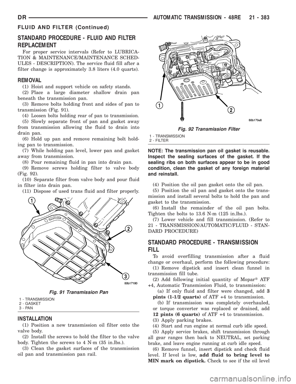
(3) Remove bolts holding front and sides of pan to
transmission (Fig. 91).
(4)
Loosen bolts holding rear of pan to transmission.
(5) Slowly separate front of pan and gasket away
from transmission allowing the fluid to drain into
drain pan.
(6) Hold up pan and remove remaining bolt hold-
ing pan to transmission.
(7) While holding pan level, lower pan and gasket
away from transmission.
(8) Pour remaining fluid in pan into drain pan.
(9) Remove screws holding filter to valve body
(Fig. 92).
(10) Separate filter from valve body and pour fluid
in filter into drain pan.
(11) Dispose of used trans fluid and filter properly.
INSTALLATION
(1) Position a new transmission oil filter onto the
valve body.
(2) Install the screws to hold the filter to the valve
body. Tighten the screws to 4 N´m (35 in.lbs.).
(3) Clean the gasket surfaces of the transmission
oil pan and transmission pan rail.NOTE: The transmission pan oil gasket is reusable.
Inspect the sealing surfaces of the gasket. If the
sealing ribs on both surfaces appear to be in good
condition, clean the gasket of any foreign material
and reinstall.
(4) Position the oil pan gasket onto the oil pan.
(5) Position the oil pan and gasket onto the trans-
mission and install several bolts to hold the pan and
gasket to the transmission.
(6) Install the remainder of the oil pan bolts.
Tighten the bolts to 13.6 N´m (125 in.lbs.).
(7) Lower vehicle and fill transmission. (Refer to
21 - TRANSMISSION/AUTOMATIC/FLUID - STAN-
DARD PROCEDURE)
STANDARD PROCEDURE - TRANSMISSION
FILL
To avoid overfilling transmission after a fluid
change or overhaul, perform the following procedure:
(1) Remove dipstick and insert clean funnel in
transmission fill tube.
(2) Add following initial quantity of MopartAT F
+4, Automatic Transmission Fluid, to transmission:
(a) If only fluid and filter were changed, add3
pints (1-1/2 quarts)of ATF +4 to transmission.
(b) If transmission was completely overhauled,
or torque converter was replaced or drained, add
12 pints (6 quarts)of ATF +4 to transmission.
(3) Apply parking brakes.
(4)
Start and run engine at normal curb idle speed.
(5)Apply service brakes, shift transmission through
all gear ranges then back to NEUTRAL, set parking
brake, and leave engine running at curb idle speed.
(6) Remove funnel, insert dipstick and check fluid
level. If level is low,add fluid to bring level to
MIN mark on dipstick.Check to see if the oil level
Fig. 91 Transmission Pan
1 - TRANSMISSION
2 - GASKET
3-PAN
Fig. 92 Transmission Filter
1 - TRANSMISSION
2 - FILTER
DRAUTOMATIC TRANSMISSION - 48RE 21 - 383
FLUID AND FILTER (Continued)
Page 2223 of 2895
is equal on both sides of the dipstick. If one side is
noticably higher than the other, the dipstick has
picked up some oil from the dipstick tube. Allow the
oil to drain down the dipstick tube and re-check.
(7) Drive vehicle until transmission fluid is at nor-
mal operating temperature.
(8) With the engine running at curb idle speed, the
gear selector in NEUTRAL, and the parking brake
applied, check the transmission fluid level.
CAUTION: Do not overfill transmission, fluid foam-
ing and shifting problems can result.
(9)
Add fluid to bring level up to MAX arrow mark.
When fluid level is correct, shut engine off, release
park brake, remove funnel, and install dipstick in fill
tube.
FRONT CLUTCH
DESCRIPTION
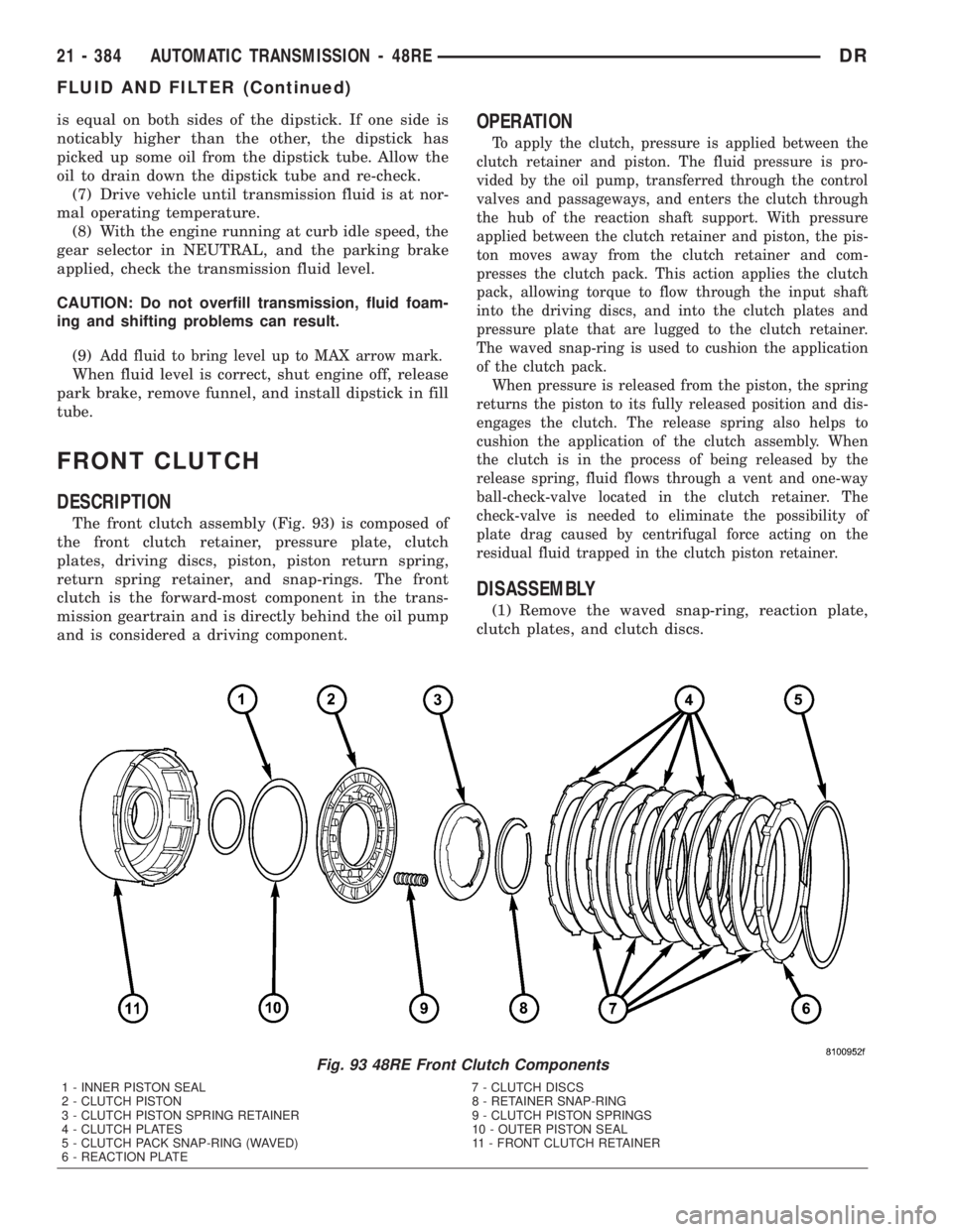
The front clutch assembly (Fig. 93) is composed of
the front clutch retainer, pressure plate, clutch
plates, driving discs, piston, piston return spring,
return spring retainer, and snap-rings. The front
clutch is the forward-most component in the trans-
mission geartrain and is directly behind the oil pump
and is considered a driving component.
OPERATION
To apply the clutch, pressure is applied between the
clutch retainer and piston. The fluid pressure is pro-
vided by the oil pump, transferred through the control
valves and passageways, and enters the clutch through
the hub of the reaction shaft support. With pressure
applied between the clutch retainer and piston, the pis-
ton moves away from the clutch retainer and com-
presses the clutch pack. This action applies the clutch
pack, allowing torque to flow through the input shaft
into the driving discs, and into the clutch plates and
pressure plate that are lugged to the clutch retainer.
The waved snap-ring is used to cushion the application
of the clutch pack.
When pressure is released from the piston, the spring
returns the piston to its fully released position and dis-
engages the clutch. The release spring also helps to
cushion the application of the clutch assembly. When
the clutch is in the process of being released by the
release spring, fluid flows through a vent and one-way
ball-check-valve located in the clutch retainer. The
check-valve is needed to eliminate the possibility of
plate drag caused by centrifugal force acting on the
residual fluid trapped in the clutch piston retainer.
DISASSEMBLY
(1) Remove the waved snap-ring, reaction plate,
clutch plates, and clutch discs.
Fig. 93 48RE Front Clutch Components
1 - INNER PISTON SEAL 7 - CLUTCH DISCS
2 - CLUTCH PISTON 8 - RETAINER SNAP-RING
3 - CLUTCH PISTON SPRING RETAINER 9 - CLUTCH PISTON SPRINGS
4 - CLUTCH PLATES 10 - OUTER PISTON SEAL
5 - CLUTCH PACK SNAP-RING (WAVED) 11 - FRONT CLUTCH RETAINER
6 - REACTION PLATE
21 - 384 AUTOMATIC TRANSMISSION - 48REDR
FLUID AND FILTER (Continued)
Page 2327 of 2895
AUTOMATIC TRANSMISSION - 45RFE/545RFE
TABLE OF CONTENTS
page page
AUTOMATIC TRANSMISSION - 45RFE/545RFE
DESCRIPTION........................489
OPERATION..........................490
DIAGNOSIS AND TESTING
DIAGNOSIS AND TESTING - AUTOMATIC
TRANSMISSION.....................491
DIAGNOSIS AND TESTING - PRELIMINARY. . 491
DIAGNOSIS AND TESTING - ROAD
TESTING...........................491
DIAGNOSIS AND TESTING - HYDRAULIC
PRESSURE TEST....................493
DIAGNOSIS AND TESTING - AIR CHECKING
TRANSMISSION CLUTCH OPERATION....494
DIAGNOSIS AND TESTING - CONVERTER
HOUSING FLUID LEAK................495
STANDARD PROCEDURE - ALUMINUM
THREAD REPAIR.....................495
REMOVAL............................495
DISASSEMBLY........................497
CLEANING...........................502
INSPECTION.........................503
ASSEMBLY...........................503
INSTALLATION........................510
SCHEMATICS AND DIAGRAMS
HYDRAULIC SCHEMATICS.............513
SPECIFICATIONS
TRANSMISSION.....................534
SPECIAL TOOLS
RFE TRANSMISSION.................535
4C RETAINER/BULKHEAD
DISASSEMBLY........................538
ASSEMBLY...........................538
ADAPTER HOUSING SEAL
REMOVAL............................539
INSTALLATION........................539
BRAKE TRANSMISSION SHIFT INTERLOCK
SYSTEM
DESCRIPTION........................540
OPERATION..........................540
DIAGNOSIS AND TESTING - BRAKE
TRANSMISSION SHIFT INTERLOCK......540
ADJUSTMENTS - BRAKE TRANSMISSION
SHIFT INTERLOCK...................540
FLUID AND FILTER
DIAGNOSIS AND TESTING
DIAGNOSIS AND TESTING - EFFECTS OF
INCORRECT FLUID LEVEL.............541
DIAGNOSIS AND TESTING - CAUSES OF
BURNT FLUID.......................541DIAGNOSIS AND TESTING - FLUID
CONTAMINATION....................541
STANDARD PROCEDURE
STANDARD PROCEDURE - FLUID LEVEL
CHECK............................542
STANDARD PROCEDURE - FLUID AND
FILTER REPLACEMENT...............542
STANDARD PROCEDURE - TRANSMISSION
FILL...............................544
GEARSHIFT CABLE
DIAGNOSIS AND TESTING - GEARSHIFT
CABLE.............................544
REMOVAL............................544
INSTALLATION........................545
ADJUSTMENTS
GEARSHIFT CABLE..................546
HOLDING CLUTCHES
DESCRIPTION........................546
OPERATION..........................546
INPUT CLUTCH ASSEMBLY
DESCRIPTION........................549
OPERATION..........................549
DISASSEMBLY........................550
ASSEMBLY...........................552
INPUT SPEED SENSOR
DESCRIPTION........................558
OPERATION..........................558
REMOVAL............................559
INSTALLATION........................559
LINE PRESSURE (LP) SENSOR
DESCRIPTION........................559
OPERATION..........................559
REMOVAL............................559
INSTALLATION........................560
LOW/REVERSE CLUTCH
DISASSEMBLY........................560
CLEANING...........................561
INSPECTION.........................561
ASSEMBLY...........................561
OIL PUMP
DESCRIPTION........................562
OPERATION..........................562
STANDARD PROCEDURE - OIL PUMP
VOLUME CHECK.....................563
DISASSEMBLY........................564
CLEANING...........................566
INSPECTION.........................566
ASSEMBLY...........................566
21 - 488 AUTOMATIC TRANSMISSION - 45RFE/545RFEDR
Page 2380 of 2895
BTSI FUNCTION CHECK
(1) Verify removal of ignition key allowed in PARK
position only.
(2) When the shift lever is in PARK, the ignition
key cylinder should rotate freely from off to lock.
When the shifter is in any other position, the ignition
key should not rotate from off to lock.
(3) Shifting out of PARK should be possible when
the ignition key cylinder is in the off position.
(4) Shifting out of PARK should not be possible
while applying normal force, and ignition key cylin-
der is in the run or start positions, unless the foot
brake pedal is depressed approximately 1/2 inch
(12mm).
(5) Shifting out of PARK should not be possible
when the ignition key cylinder is in the accessory or
lock position.
(6) Shifting between any gear and NEUTRAL, or
PARK, may be done without depressing foot brake
with ignition switch in run or start positions.
(7) Engine starts must be possible with shifter
lever in PARK or NEUTRAL positions only. Engine
starts must not be possible in any position other than
PARK or NEUTRAL.
(8) With shifter lever in the:
²PARK position - Apply upward force on the shift
arm and remove pressure. Engine starts must be
possible.
²PARK position - Apply downward force on the
shift arm and remove pressure. Engine starts must
be possible.
²NEUTRAL position - Normal position. Engine
starts must be possible.²NEUTRAL position - Engine running and brakes
applied, apply upward force on the shift arm. Trans-
mission shall not be able to shift from neutral to
reverse.
FLUID AND FILTER
DIAGNOSIS AND TESTING
DIAGNOSIS AND TESTING - EFFECTS OF
INCORRECT FLUID LEVEL
A low fluid level allows the pump to take in air
along with the fluid. Air in the fluid will cause fluid
pressures to be low and develop slower than normal.
If the transmission is overfilled, the gears churn the
fluid into foam. This aerates the fluid and causing
the same conditions occurring with a low level. In
either case, air bubbles cause fluid overheating, oxi-
dation and varnish buildup which interferes with
valve and clutch operation. Foaming also causes fluid
expansion which can result in fluid overflow from the
transmission vent or fill tube. Fluid overflow can eas-
ily be mistaken for a leak if inspection is not careful.
DIAGNOSIS AND TESTING - CAUSES OF
BURNT FLUID
Burnt, discolored fluid is a result of overheating
which has three primary causes.
(1) Internal clutch slippage, usually caused by low
line pressure, inadequate clutch apply pressure, or
clutch seal failure.
(2) A result of restricted fluid flow through the
main and/or auxiliary cooler. This condition is usu-
ally the result of a faulty or improperly installed
drainback valve, a damaged main cooler, or severe
restrictions in the coolers and lines caused by debris
or kinked lines.
(3) Heavy duty operation with a vehicle not prop-
erly equipped for this type of operation. Trailer tow-
ing or similar high load operation will overheat the
transmission fluid if the vehicle is improperly
equipped. Such vehicles should have an auxiliary
transmission fluid cooler, a heavy duty cooling sys-
tem, and the engine/axle ratio combination needed to
handle heavy loads.
DIAGNOSIS AND TESTING - FLUID
CONTAMINATION
Transmission fluid contamination is generally a
result of:
²adding incorrect fluid
²failure to clean dipstick and fill tube when
checking level
²engine coolant entering the fluid
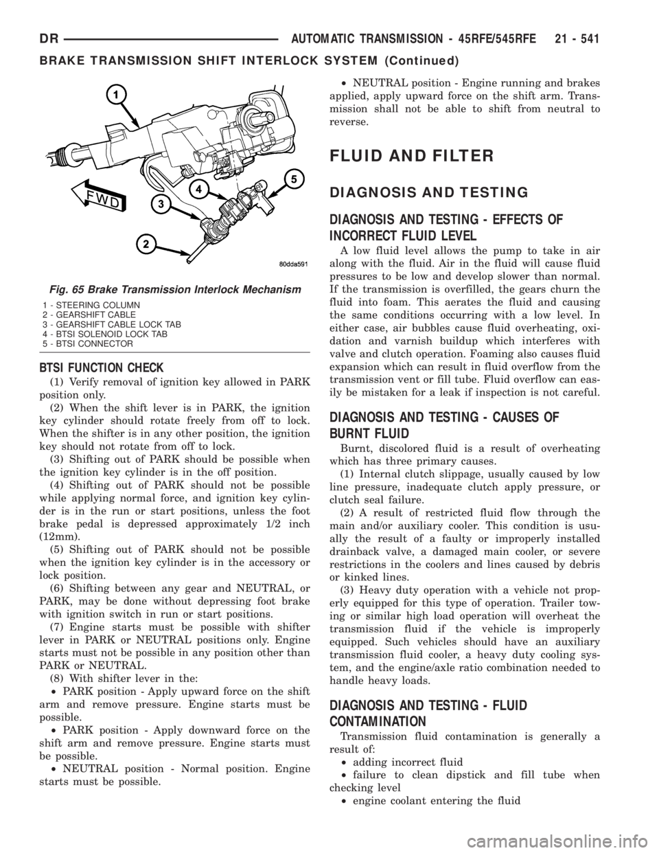
Fig. 65 Brake Transmission Interlock Mechanism
1 - STEERING COLUMN
2 - GEARSHIFT CABLE
3 - GEARSHIFT CABLE LOCK TAB
4 - BTSI SOLENOID LOCK TAB
5 - BTSI CONNECTOR
DRAUTOMATIC TRANSMISSION - 45RFE/545RFE 21 - 541
BRAKE TRANSMISSION SHIFT INTERLOCK SYSTEM (Continued)
Page 2381 of 2895
²internal failure that generates debris
²overheat that generates sludge (fluid break-
down)
²failure to replace contaminated converter after
repair
The use of non-recommended fluids can result in
transmission failure. The usual results are erratic
shifts, slippage, abnormal wear and eventual failure
due to fluid breakdown and sludge formation. Avoid
this condition by using recommended fluids only.
The dipstick cap and fill tube should be wiped
clean before checking fluid level. Dirt, grease and
other foreign material on the cap and tube could fall
into the tube if not removed beforehand. Take the
time to wipe the cap and tube clean before withdraw-
ing the dipstick.
Engine coolant in the transmission fluid is gener-
ally caused by a cooler malfunction. The only remedy
is to replace the radiator as the cooler in the radiator
is not a serviceable part. If coolant has circulated
through the transmission, an overhaul is necessary.
The torque converter should be replaced whenever
a failure generates sludge and debris. This is neces-
sary because normal converter flushing procedures
will not remove all contaminants.
STANDARD PROCEDURE
STANDARD PROCEDURE - FLUID LEVEL
CHECK
Low fluid level can cause a variety of conditions
because it allows the pump to take in air along with
the fluid. As in any hydraulic system, air bubbles
make the fluid spongy, therefore, pressures will be
low and build up slowly.
Improper filling can also raise the fluid level too
high. When the transmssion has too much fluid, the
geartrain churns up foam and cause the same condi-
tions which occur with a low fluid level.
In either case, air bubbles can cause overheating
and/or fluid oxidation, and varnishing. This can
interfere with normal valve, clutch, and accumulator
operation. Foaming can also result in fluid escaping
from the transmission vent where it may be mis-
taken for a leak.
After the fluid has been checked, seat the dipstick
fully to seal out water and dirt.
The transmission has a dipstick to check oil level.
It is located on the right side of the engine. Be sure
to wipe all dirt from dipstick handle before removing.
The torque converter fills in both the P (PARK)
and N (NEUTRAL) positions. Place the selector lever
in P (PARK) to be sure that the fluid level check is
accurate.The engine should be running at idle
speed for at least one minute, with the vehicleon level ground.At normal operating temperature
(approximately 82 C. or 180 F.), the fluid level is cor-
rect if it is in the HOT region (cross-hatched area) on
the oil level indicator. The fluid level will be approx-
imately at the upper COLD hole of the dipstick at
70É F fluid temperature.
NOTE: Engine and Transmission should be at nor-
mal operating temperature before performing this
procedure.
(1) Start engine and apply parking brake.
(2) Shift the transmission into DRIVE for approxi-
mately 2 seconds.
(3) Shift the transmission into REVERSE for
approximately 2 seconds.
(4) Shift the transmission into PARK.
(5) Hook up DRBtscan tool and select transmis-
sion.
(6) Select sensors.
(7) Read the transmission temperature value.
(8) Compare the fluid temperature value with the
chart. (Fig. 66)
(9) Adjust transmission fluid level shown on the
dipstick according to the chart.
NOTE: After adding any fluid to the transmission,
wait a minimum of 2 minutes for the oil to fully
drain from the fill tube into the transmission before
rechecking the fluid level.
(10) Check transmission for leaks.
STANDARD PROCEDURE - FLUID AND FILTER
REPLACEMENT
For proper service intervals (Refer to LUBRICA-
TION & MAINTENANCE/MAINTENANCE SCHED-
ULES - DESCRIPTION).
REMOVAL
(1) Hoist and support vehicle on safety stands.
(2) Place a large diameter shallow drain pan
beneath the transmission pan.
(3) Remove bolts holding front and sides of pan to
transmission.
(4) Loosen bolts holding rear of pan to transmis-
sion.
(5) Slowly separate front of pan away from trans-
mission allowing the fluid to drain into drain pan.
(6) Hold up pan and remove remaining bolts hold-
ing pan to transmission.
(7) While holding pan level, lower pan away from
transmission.
(8) Pour remaining fluid in pan into drain pan.
(9) Remove screw holding filter to valve body (Fig.
67).
21 - 542 AUTOMATIC TRANSMISSION - 45RFE/545RFEDR
FLUID AND FILTER (Continued)
Page 2383 of 2895
(2) Place replacement filter in position on valve
body and into the oil pump.
(3) Install screw to hold filter to valve body (Fig.
67). Tighten screw to 4.5 N´m (40 in. lbs.) torque.
(4) Install new cooler return filter onto the trans-
mission, if necessary. Torque the filter to 14.12 N´m
(125 in.lbs.).
(5) Place bead of MopartRTV sealant onto the
transmission case sealing surface.
(6) Place pan in position on transmission.
(7) Install bolts to hold pan to transmission.
Tighten bolts to 11.8 N´m (105 in. lbs.) torque.
(8) Lower vehicle and fill transmission with
MopartATF +4.
STANDARD PROCEDURE - TRANSMISSION
FILL
To avoid overfilling transmission after a fluid
change or overhaul, perform the following procedure:
(1) Remove dipstick and insert clean funnel in
transmission fill tube.
(2) Add following initial quantity of MopartAT F
+4 to transmission:
(a) If only fluid and filter were changed, add10
pints (5 quarts)of ATF +4 to transmission.
(b) If transmission was completely overhauled
and the torque converter was replaced or drained,
add24 pints (12 quarts)of ATF +4 to transmis-
sion.
(3) Check the transmission fluid (Refer to 21 -
TRANSMISSION/AUTOMATIC - RFE/FLUID -
STANDARD PROCEDURE) and adjust as required.
GEARSHIFT CABLE
DIAGNOSIS AND TESTING - GEARSHIFT
CABLE
(1) Engine starts must be possible with shift lever
in PARK or NEUTRAL positions only. Engine starts
must not be possible in any other gear position.
(2) With the shift lever in the:
(a) PARK position - Apply upward force on the
shift arm and remove pressure. Engine starts must
be possible.
(b) PARK position - Apply downward force on
the shift arm and remove pressure. Engine starts
must be possible.
(c) NEUTRAL position - Normal position. Engine
starts must be possible.
(d) NEUTRAL position - Engine running and
brakes applied, apply upward force on the shift
arm. Transmission shall not be able to shift from
neutral to reverse.
REMOVAL
(1) Shift transmission into PARK.
(2) Raise vehicle.
(3) Disengage cable eyelet at transmission shift
lever and pull cable adjuster out of mounting bracket
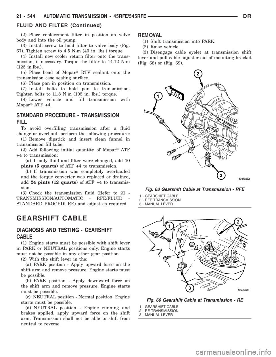
(Fig. 68) or (Fig. 69).
Fig. 68 Gearshift Cable at Transmission - RFE
1 - GEARSHIFT CABLE
2 - RFE TRANSMISSION
3 - MANUAL LEVER
Fig. 69 Gearshift Cable at Transmission - RE
1 - GEARSHIFT CABLE
2 - RE TRANSMISSION
3 - MANUAL LEVER
21 - 544 AUTOMATIC TRANSMISSION - 45RFE/545RFEDR
FLUID AND FILTER (Continued)