2003 DODGE RAM width
[x] Cancel search: widthPage 2270 of 2895
SOLENOID
DESCRIPTION
The typical electrical solenoid used in automotive
applications is a linear actuator. It is a device that
produces motion in a straight line. This straight line
motion can be either forward or backward in direc-
tion, and short or long distance.
A solenoid is an electromechanical device that uses
a magnetic force to perform work. It consists of a coil
of wire, wrapped around a magnetic core made from
steel or iron, and a spring loaded, movable plunger,
which performs the work, or straight line motion.
The solenoids used in transmission applications
are attached to valves which can be classified asnor-
mally openornormally closed. Thenormally
opensolenoid valve is defined as a valve which
allows hydraulic flow when no current or voltage is
applied to the solenoid. Thenormally closedsole-
noid valve is defined as a valve which does not allow
hydraulic flow when no current or voltage is applied
to the solenoid. These valves perform hydraulic con-
trol functions for the transmission and must there-
fore be durable and tolerant of dirt particles. For
these reasons, the valves have hardened steel pop-
pets and ball valves. The solenoids operate the valves
directly, which means that the solenoids must have
very high outputs to close the valves against the siz-
able flow areas and line pressures found in current
transmissions. Fast response time is also necessary
to ensure accurate control of the transmission.
The strength of the magnetic field is the primary
force that determines the speed of operation in a par-
ticular solenoid design. A stronger magnetic field will
cause the plunger to move at a greater speed than a
weaker one. There are basically two ways to increase
the force of the magnetic field:
1. Increase the amount of current applied to the
coil or
2. Increase the number of turns of wire in the coil.
The most common practice is to increase the num-
ber of turns by using thin wire that can completely
fill the available space within the solenoid housing.
The strength of the spring and the length of the
plunger also contribute to the response speed possi-
ble by a particular solenoid design.
A solenoid can also be described by the method by
which it is controlled. Some of the possibilities
include variable force, pulse-width modulated, con-
stant ON, or duty cycle. The variable force and pulse-
width modulated versions utilize similar methods to
control the current flow through the solenoid to posi-
tion the solenoid plunger at a desired position some-
where between full ON and full OFF. The constant
ON and duty cycled versions control the voltageacross the solenoid to allow either full flow or no flow
through the solenoid's valve.OPERATION
When an electrical current is applied to the sole-
noid coil, a magnetic field is created which produces
an attraction to the plunger, causing the plunger to
move and work against the spring pressure and the
load applied by the fluid the valve is controlling. The
plunger is normally directly attached to the valve
which it is to operate. When the current is removed
from the coil, the attraction is removed and the
plunger will return to its original position due to
spring pressure.
The plunger is made of a conductive material and
accomplishes this movement by providing a path for
the magnetic field to flow. By keeping the air gap
between the plunger and the coil to the minimum
necessary to allow free movement of the plunger, the
magnetic field is maximized.
SPEED SENSOR
DESCRIPTION
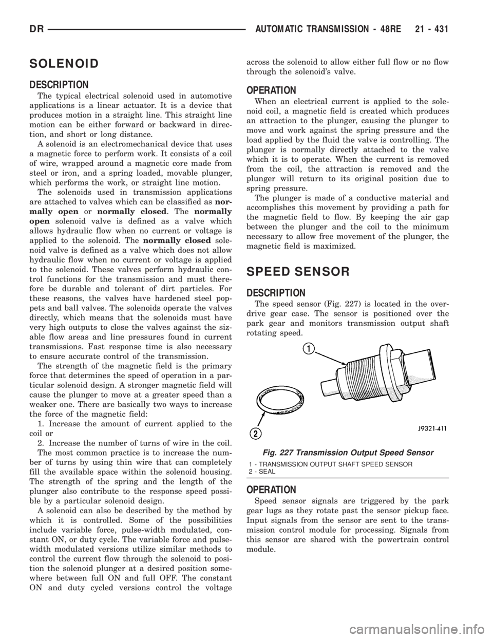
The speed sensor (Fig. 227) is located in the over-
drive gear case. The sensor is positioned over the
park gear and monitors transmission output shaft
rotating speed.
OPERATION
Speed sensor signals are triggered by the park
gear lugs as they rotate past the sensor pickup face.
Input signals from the sensor are sent to the trans-
mission control module for processing. Signals from
this sensor are shared with the powertrain control
module.
Fig. 227 Transmission Output Speed Sensor
1 - TRANSMISSION OUTPUT SHAFT SPEED SENSOR
2 - SEAL
DRAUTOMATIC TRANSMISSION - 48RE 21 - 431
Page 2414 of 2895
The strength of the magnetic field is the primary
force that determines the speed of operation in a par-
ticular solenoid design. A stronger magnetic field will
cause the plunger to move at a greater speed than a
weaker one. There are basically two ways to increase
the force of the magnetic field:
1. Increase the amount of current applied to the
coil or
2. Increase the number of turns of wire in the coil.
The most common practice is to increase the num-
ber of turns by using thin wire that can completely
fill the available space within the solenoid housing.
The strength of the spring and the length of the
plunger also contribute to the response speed possi-
ble by a particular solenoid design.
A solenoid can also be described by the method by
which it is controlled. Some of the possibilities
include variable force, pulse-width modulated, con-
stant ON, or duty cycle. The variable force and pulse-
width modulated versions utilize similar methods to
control the current flow through the solenoid to posi-
tion the solenoid plunger at a desired position some-
where between full ON and full OFF. The constant
ON and duty cycled versions control the voltage
across the solenoid to allow either full flow or no flow
through the solenoid's valve.
OPERATION
When an electrical current is applied to the sole-
noid coil, a magnetic field is created which produces
an attraction to the plunger, causing the plunger to
move and work against the spring pressure and the
load applied by the fluid the valve is controlling. The
plunger is normally directly attached to the valve
which it is to operate. When the current is removed
from the coil, the attraction is removed and the
plunger will return to its original position due to
spring pressure.
The plunger is made of a conductive material and
accomplishes this movement by providing a path for
the magnetic field to flow. By keeping the air gap
between the plunger and the coil to the minimum
necessary to allow free movement of the plunger, the
magnetic field is maximized.
TORQUE CONVERTER
DESCRIPTION
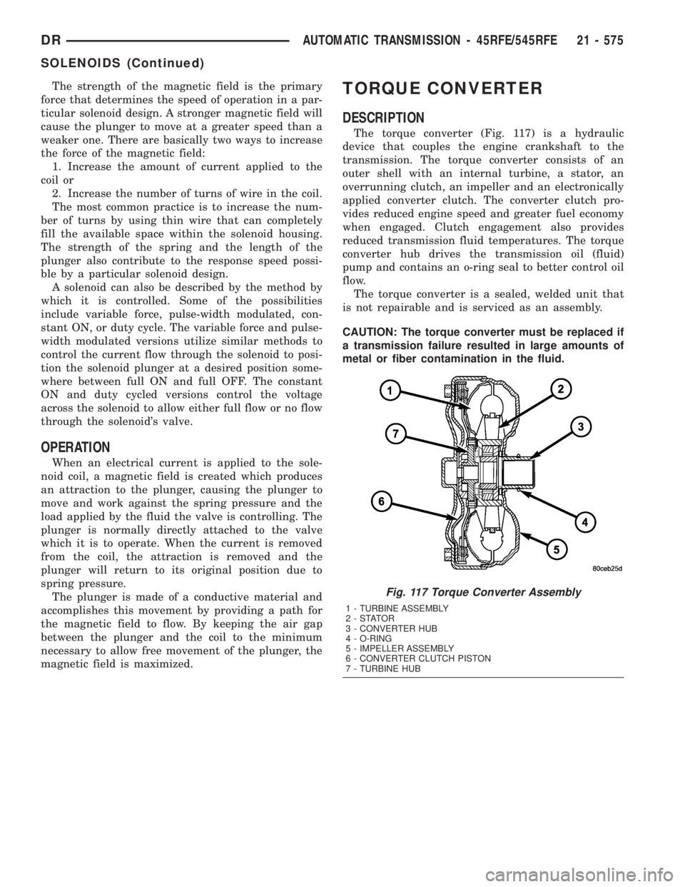
The torque converter (Fig. 117) is a hydraulic
device that couples the engine crankshaft to the
transmission. The torque converter consists of an
outer shell with an internal turbine, a stator, an
overrunning clutch, an impeller and an electronically
applied converter clutch. The converter clutch pro-
vides reduced engine speed and greater fuel economy
when engaged. Clutch engagement also provides
reduced transmission fluid temperatures. The torque
converter hub drives the transmission oil (fluid)
pump and contains an o-ring seal to better control oil
flow.
The torque converter is a sealed, welded unit that
is not repairable and is serviced as an assembly.
CAUTION: The torque converter must be replaced if
a transmission failure resulted in large amounts of
metal or fiber contamination in the fluid.
Fig. 117 Torque Converter Assembly
1 - TURBINE ASSEMBLY
2-STATOR
3 - CONVERTER HUB
4 - O-RING
5 - IMPELLER ASSEMBLY
6 - CONVERTER CLUTCH PISTON
7 - TURBINE HUB
DRAUTOMATIC TRANSMISSION - 45RFE/545RFE 21 - 575
SOLENOIDS (Continued)
Page 2451 of 2895
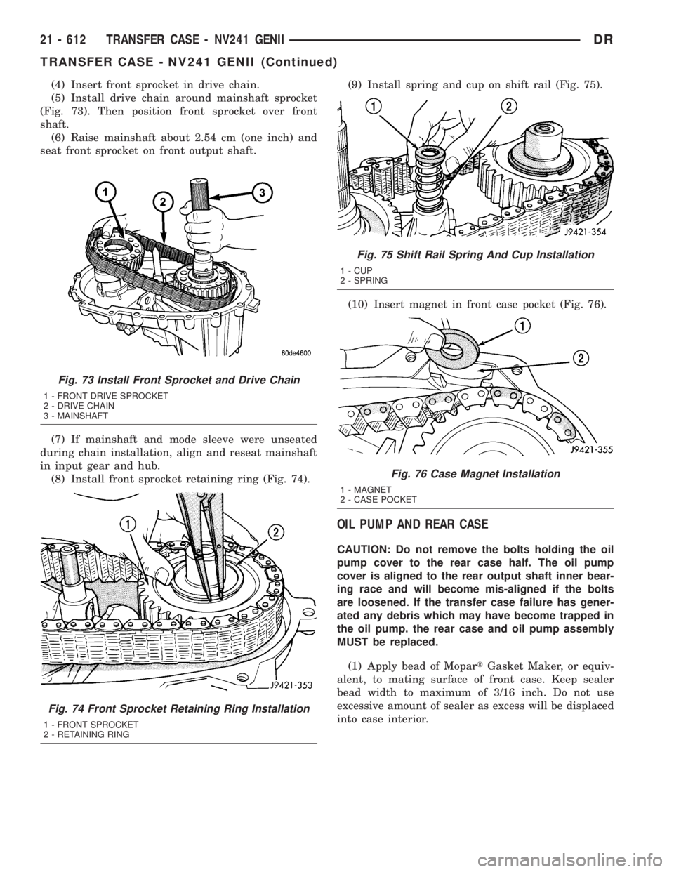
(4) Insert front sprocket in drive chain.
(5) Install drive chain around mainshaft sprocket
(Fig. 73). Then position front sprocket over front
shaft.
(6) Raise mainshaft about 2.54 cm (one inch) and
seat front sprocket on front output shaft.
(7) If mainshaft and mode sleeve were unseated
during chain installation, align and reseat mainshaft
in input gear and hub.
(8) Install front sprocket retaining ring (Fig. 74).(9) Install spring and cup on shift rail (Fig. 75).
(10) Insert magnet in front case pocket (Fig. 76).
OIL PUMP AND REAR CASE
CAUTION: Do not remove the bolts holding the oil
pump cover to the rear case half. The oil pump
cover is aligned to the rear output shaft inner bear-
ing race and will become mis-aligned if the bolts
are loosened. If the transfer case failure has gener-
ated any debris which may have become trapped in
the oil pump. the rear case and oil pump assembly
MUST be replaced.
(1) Apply bead of MopartGasket Maker, or equiv-
alent, to mating surface of front case. Keep sealer
bead width to maximum of 3/16 inch. Do not use
excessive amount of sealer as excess will be displaced
into case interior.
Fig. 73 Install Front Sprocket and Drive Chain
1 - FRONT DRIVE SPROCKET
2 - DRIVE CHAIN
3 - MAINSHAFT
Fig. 74 Front Sprocket Retaining Ring Installation
1 - FRONT SPROCKET
2 - RETAINING RING
Fig. 75 Shift Rail Spring And Cup Installation
1 - CUP
2 - SPRING
Fig. 76 Case Magnet Installation
1 - MAGNET
2 - CASE POCKET
21 - 612 TRANSFER CASE - NV241 GENIIDR
TRANSFER CASE - NV241 GENII (Continued)
Page 2453 of 2895
REAR EXTENSION
(1) Install new seal in rear extension housing seal
with Installer D-163 and Handle C-4171..
(2) Apply bead of MopartGasket Maker, or equiv-
alent, to mating surface of rear extension housing.
Keep sealer bead width to maximum of 3/16 inch. Do
not use excessive amount of sealer as excess could be
displaced into output bearing.
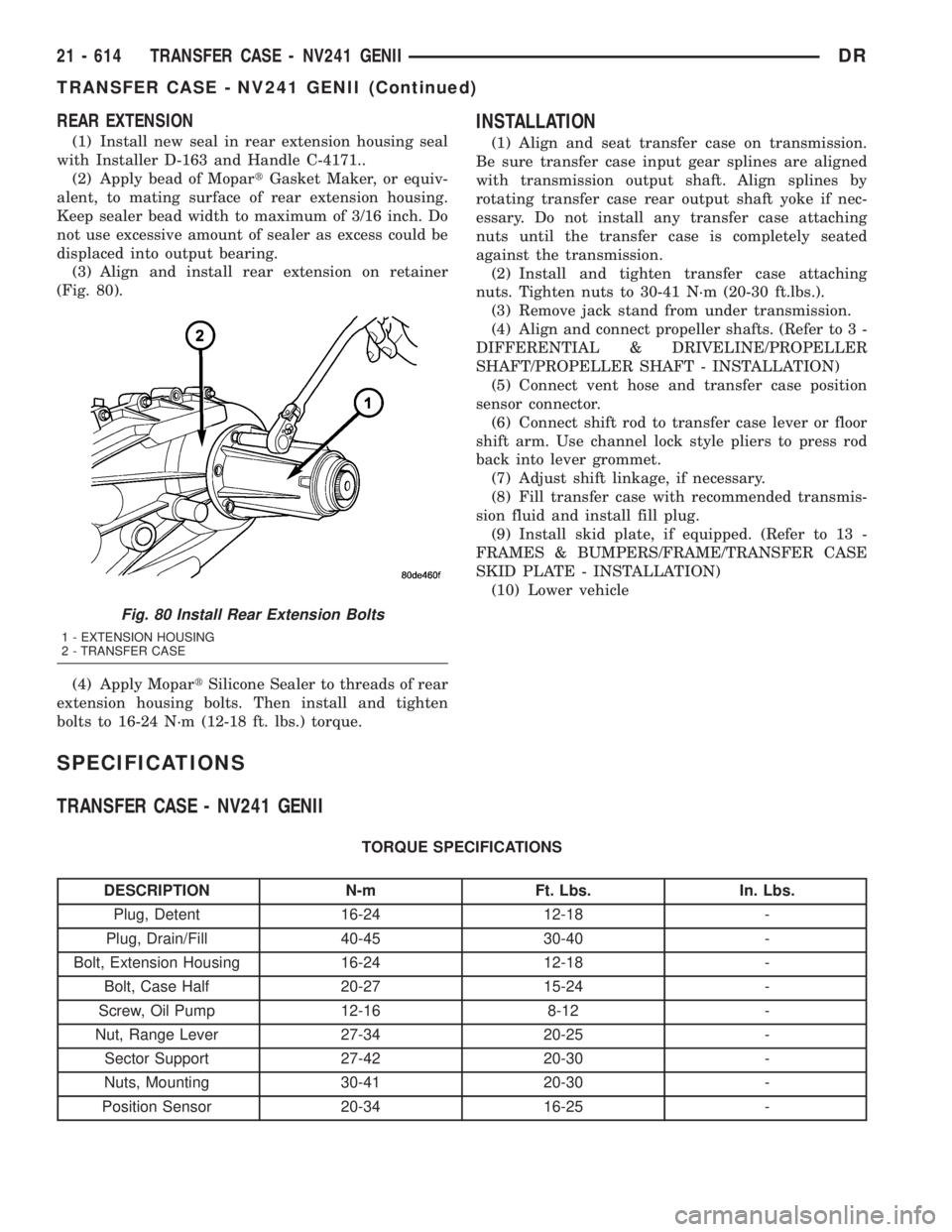
(3) Align and install rear extension on retainer
(Fig. 80).
(4) Apply MopartSilicone Sealer to threads of rear
extension housing bolts. Then install and tighten
bolts to 16-24 N´m (12-18 ft. lbs.) torque.
INSTALLATION
(1) Align and seat transfer case on transmission.
Be sure transfer case input gear splines are aligned
with transmission output shaft. Align splines by
rotating transfer case rear output shaft yoke if nec-
essary. Do not install any transfer case attaching
nuts until the transfer case is completely seated
against the transmission.
(2) Install and tighten transfer case attaching
nuts. Tighten nuts to 30-41 N´m (20-30 ft.lbs.).
(3) Remove jack stand from under transmission.
(4) Align and connect propeller shafts. (Refer to 3 -
DIFFERENTIAL & DRIVELINE/PROPELLER
SHAFT/PROPELLER SHAFT - INSTALLATION)
(5) Connect vent hose and transfer case position
sensor connector.
(6) Connect shift rod to transfer case lever or floor
shift arm. Use channel lock style pliers to press rod
back into lever grommet.
(7) Adjust shift linkage, if necessary.
(8) Fill transfer case with recommended transmis-
sion fluid and install fill plug.
(9) Install skid plate, if equipped. (Refer to 13 -
FRAMES & BUMPERS/FRAME/TRANSFER CASE
SKID PLATE - INSTALLATION)
(10) Lower vehicle
SPECIFICATIONS
TRANSFER CASE - NV241 GENII
TORQUE SPECIFICATIONS
DESCRIPTION N-m Ft. Lbs. In. Lbs.
Plug, Detent 16-24 12-18 -
Plug, Drain/Fill 40-45 30-40 -
Bolt, Extension Housing 16-24 12-18 -
Bolt, Case Half 20-27 15-24 -
Screw, Oil Pump 12-16 8-12 -
Nut, Range Lever 27-34 20-25 -
Sector Support 27-42 20-30 -
Nuts, Mounting 30-41 20-30 -
Position Sensor 20-34 16-25 -
Fig. 80 Install Rear Extension Bolts
1 - EXTENSION HOUSING
2 - TRANSFER CASE
21 - 614 TRANSFER CASE - NV241 GENIIDR
TRANSFER CASE - NV241 GENII (Continued)
Page 2485 of 2895
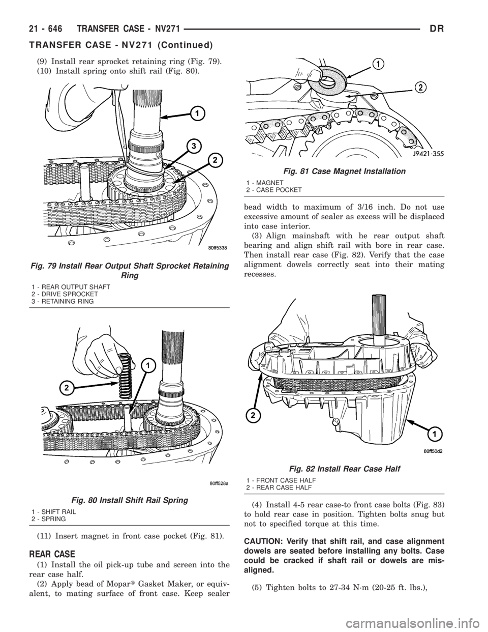
(9) Install rear sprocket retaining ring (Fig. 79).
(10) Install spring onto shift rail (Fig. 80).
(11) Insert magnet in front case pocket (Fig. 81).
REAR CASE
(1) Install the oil pick-up tube and screen into the
rear case half.
(2) Apply bead of MopartGasket Maker, or equiv-
alent, to mating surface of front case. Keep sealerbead width to maximum of 3/16 inch. Do not use
excessive amount of sealer as excess will be displaced
into case interior.
(3) Align mainshaft with he rear output shaft
bearing and align shift rail with bore in rear case.
Then install rear case (Fig. 82). Verify that the case
alignment dowels correctly seat into their mating
recesses.
(4) Install 4-5 rear case-to front case bolts (Fig. 83)
to hold rear case in position. Tighten bolts snug but
not to specified torque at this time.
CAUTION: Verify that shift rail, and case alignment
dowels are seated before installing any bolts. Case
could be cracked if shaft rail or dowels are mis-
aligned.
(5) Tighten bolts to 27-34 N´m (20-25 ft. lbs.),
Fig. 79 Install Rear Output Shaft Sprocket Retaining
Ring
1 - REAR OUTPUT SHAFT
2 - DRIVE SPROCKET
3 - RETAINING RING
Fig. 80 Install Shift Rail Spring
1 - SHIFT RAIL
2 - SPRING
Fig. 81 Case Magnet Installation
1 - MAGNET
2 - CASE POCKET
Fig. 82 Install Rear Case Half
1 - FRONT CASE HALF
2 - REAR CASE HALF
21 - 646 TRANSFER CASE - NV271DR
TRANSFER CASE - NV271 (Continued)
Page 2487 of 2895
(3) Apply bead of MopartGasket Maker, or equiv-
alent, to mating surface of rear extension housing.
Keep sealer bead width to maximum of 3/16 inch. Do
not use excessive amount of sealer as excess could be
displaced into output bearing.
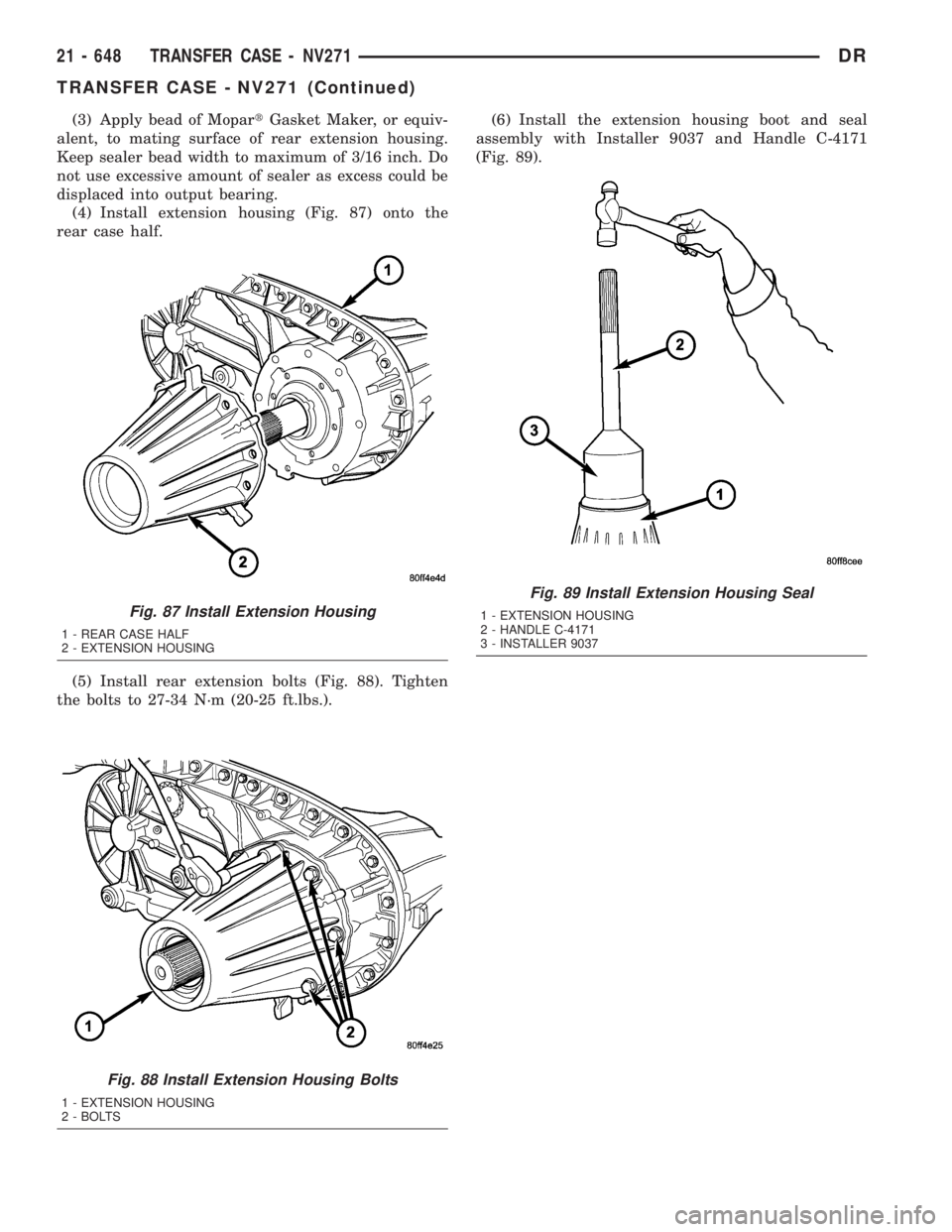
(4) Install extension housing (Fig. 87) onto the
rear case half.
(5) Install rear extension bolts (Fig. 88). Tighten
the bolts to 27-34 N´m (20-25 ft.lbs.).(6) Install the extension housing boot and seal
assembly with Installer 9037 and Handle C-4171
(Fig. 89).
Fig. 87 Install Extension Housing
1 - REAR CASE HALF
2 - EXTENSION HOUSING
Fig. 88 Install Extension Housing Bolts
1 - EXTENSION HOUSING
2 - BOLTS
Fig. 89 Install Extension Housing Seal
1 - EXTENSION HOUSING
2 - HANDLE C-4171
3 - INSTALLER 9037
21 - 648 TRANSFER CASE - NV271DR
TRANSFER CASE - NV271 (Continued)
Page 2517 of 2895
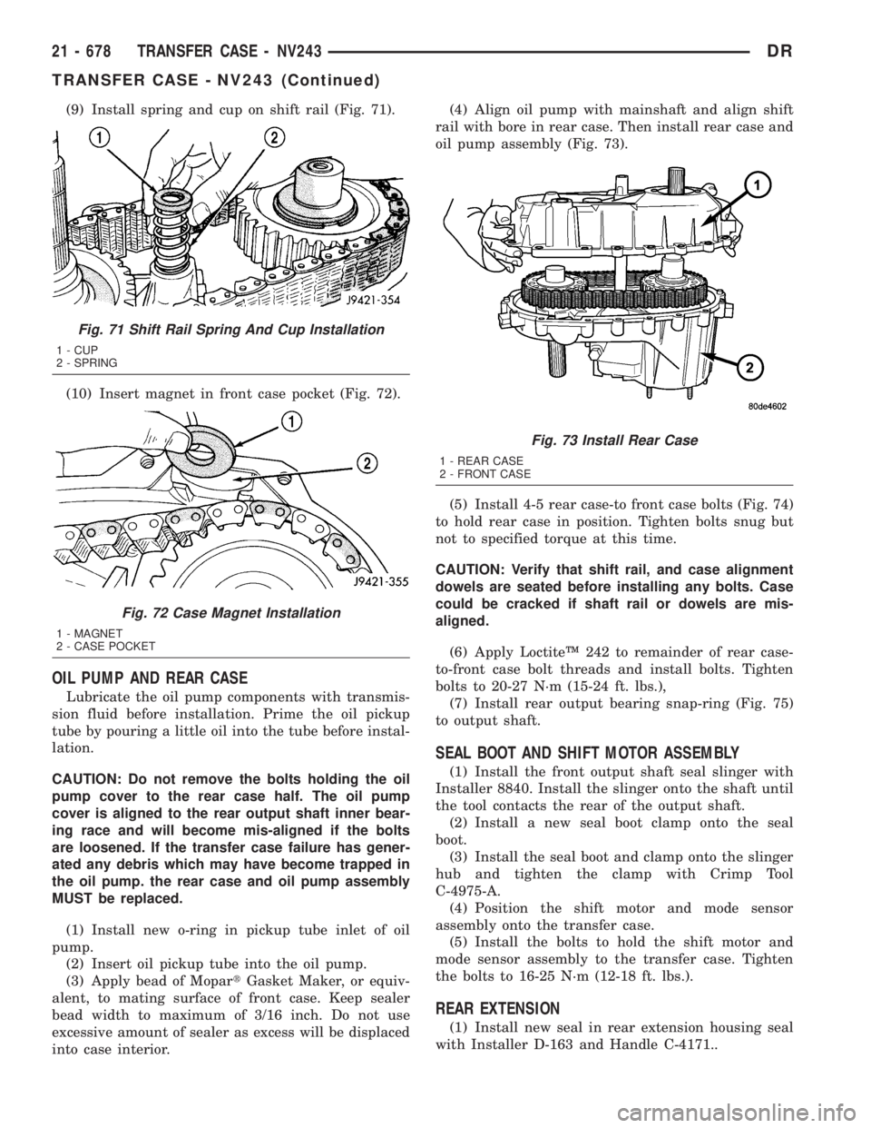
(9) Install spring and cup on shift rail (Fig. 71).
(10) Insert magnet in front case pocket (Fig. 72).
OIL PUMP AND REAR CASE
Lubricate the oil pump components with transmis-
sion fluid before installation. Prime the oil pickup
tube by pouring a little oil into the tube before instal-
lation.
CAUTION: Do not remove the bolts holding the oil
pump cover to the rear case half. The oil pump
cover is aligned to the rear output shaft inner bear-
ing race and will become mis-aligned if the bolts
are loosened. If the transfer case failure has gener-
ated any debris which may have become trapped in
the oil pump. the rear case and oil pump assembly
MUST be replaced.
(1) Install new o-ring in pickup tube inlet of oil
pump.
(2) Insert oil pickup tube into the oil pump.
(3) Apply bead of MopartGasket Maker, or equiv-
alent, to mating surface of front case. Keep sealer
bead width to maximum of 3/16 inch. Do not use
excessive amount of sealer as excess will be displaced
into case interior.(4) Align oil pump with mainshaft and align shift
rail with bore in rear case. Then install rear case and
oil pump assembly (Fig. 73).
(5) Install 4-5 rear case-to front case bolts (Fig. 74)
to hold rear case in position. Tighten bolts snug but
not to specified torque at this time.
CAUTION: Verify that shift rail, and case alignment
dowels are seated before installing any bolts. Case
could be cracked if shaft rail or dowels are mis-
aligned.
(6) Apply LoctiteŸ 242 to remainder of rear case-
to-front case bolt threads and install bolts. Tighten
bolts to 20-27 N´m (15-24 ft. lbs.),
(7) Install rear output bearing snap-ring (Fig. 75)
to output shaft.
SEAL BOOT AND SHIFT MOTOR ASSEMBLY
(1) Install the front output shaft seal slinger with
Installer 8840. Install the slinger onto the shaft until
the tool contacts the rear of the output shaft.
(2) Install a new seal boot clamp onto the seal
boot.
(3) Install the seal boot and clamp onto the slinger
hub and tighten the clamp with Crimp Tool
C-4975-A.
(4) Position the shift motor and mode sensor
assembly onto the transfer case.
(5) Install the bolts to hold the shift motor and
mode sensor assembly to the transfer case. Tighten
the bolts to 16-25 N´m (12-18 ft. lbs.).
REAR EXTENSION
(1) Install new seal in rear extension housing seal
with Installer D-163 and Handle C-4171..
Fig. 71 Shift Rail Spring And Cup Installation
1 - CUP
2 - SPRING
Fig. 72 Case Magnet Installation
1 - MAGNET
2 - CASE POCKET
Fig. 73 Install Rear Case
1 - REAR CASE
2 - FRONT CASE
21 - 678 TRANSFER CASE - NV243DR
TRANSFER CASE - NV243 (Continued)
Page 2518 of 2895
(2) Apply bead of MopartGasket Maker, or equiv-
alent, to mating surface of rear extension housing.
Keep sealer bead width to maximum of 3/16 inch. Do
not use excessive amount of sealer as excess could be
displaced into output bearing.(3) Align and install rear extension on retainer
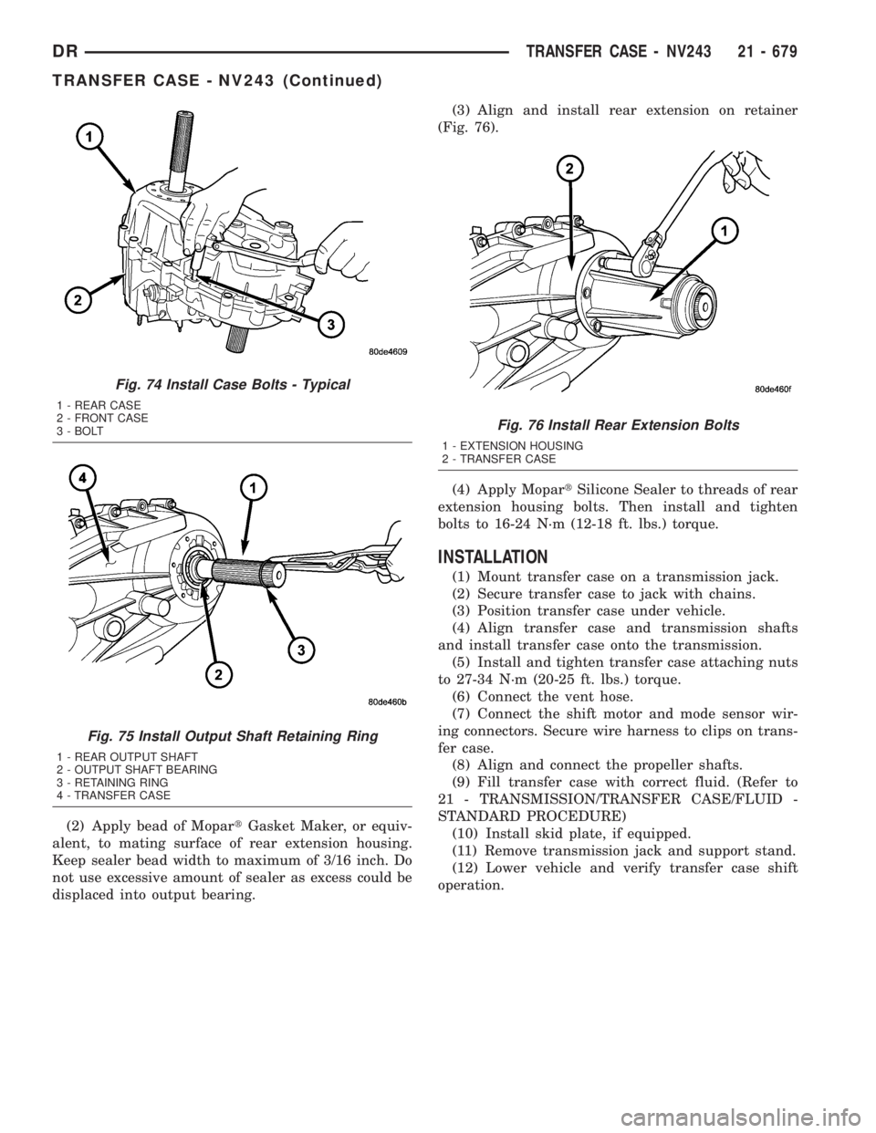
(Fig. 76).
(4) Apply MopartSilicone Sealer to threads of rear
extension housing bolts. Then install and tighten
bolts to 16-24 N´m (12-18 ft. lbs.) torque.
INSTALLATION
(1) Mount transfer case on a transmission jack.
(2) Secure transfer case to jack with chains.
(3) Position transfer case under vehicle.
(4) Align transfer case and transmission shafts
and install transfer case onto the transmission.
(5) Install and tighten transfer case attaching nuts
to 27-34 N´m (20-25 ft. lbs.) torque.
(6) Connect the vent hose.
(7) Connect the shift motor and mode sensor wir-
ing connectors. Secure wire harness to clips on trans-
fer case.
(8) Align and connect the propeller shafts.
(9) Fill transfer case with correct fluid. (Refer to
21 - TRANSMISSION/TRANSFER CASE/FLUID -
STANDARD PROCEDURE)
(10) Install skid plate, if equipped.
(11) Remove transmission jack and support stand.
(12) Lower vehicle and verify transfer case shift
operation.
Fig. 74 Install Case Bolts - Typical
1 - REAR CASE
2 - FRONT CASE
3 - BOLT
Fig. 75 Install Output Shaft Retaining Ring
1 - REAR OUTPUT SHAFT
2 - OUTPUT SHAFT BEARING
3 - RETAINING RING
4 - TRANSFER CASE
Fig. 76 Install Rear Extension Bolts
1 - EXTENSION HOUSING
2 - TRANSFER CASE
DRTRANSFER CASE - NV243 21 - 679
TRANSFER CASE - NV243 (Continued)