2003 DODGE RAM width
[x] Cancel search: widthPage 1625 of 2895
REFACING VALVES AND VALVE SEATS
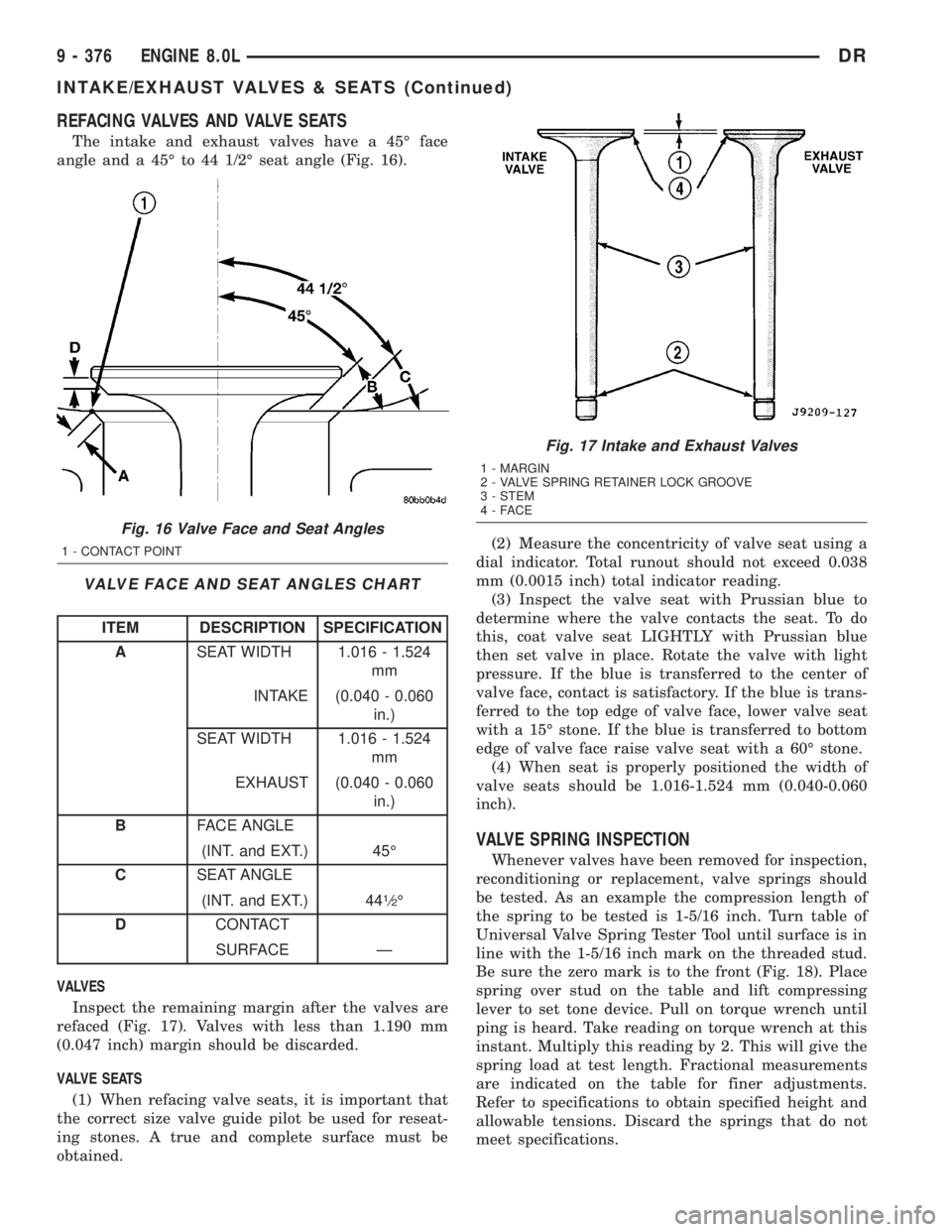
The intake and exhaust valves have a 45É face
angle and a 45É to 44 1/2É seat angle (Fig. 16).
VALVE FACE AND SEAT ANGLES CHART
ITEM DESCRIPTION SPECIFICATION
ASEAT WIDTH 1.016 - 1.524
mm
INTAKE (0.040 - 0.060
in.)
SEAT WIDTH 1.016 - 1.524
mm
EXHAUST (0.040 - 0.060
in.)
BFACE ANGLE
(INT. and EXT.) 45É
CSEAT ANGLE
(INT. and EXT.) 44
1¤2É
DCONTACT
SURFACE Ð
VALVES
Inspect the remaining margin after the valves are
refaced (Fig. 17). Valves with less than 1.190 mm
(0.047 inch) margin should be discarded.
VALVE SEATS
(1) When refacing valve seats, it is important that
the correct size valve guide pilot be used for reseat-
ing stones. A true and complete surface must be
obtained.(2) Measure the concentricity of valve seat using a
dial indicator. Total runout should not exceed 0.038
mm (0.0015 inch) total indicator reading.
(3) Inspect the valve seat with Prussian blue to
determine where the valve contacts the seat. To do
this, coat valve seat LIGHTLY with Prussian blue
then set valve in place. Rotate the valve with light
pressure. If the blue is transferred to the center of
valve face, contact is satisfactory. If the blue is trans-
ferred to the top edge of valve face, lower valve seat
with a 15É stone. If the blue is transferred to bottom
edge of valve face raise valve seat with a 60É stone.
(4) When seat is properly positioned the width of
valve seats should be 1.016-1.524 mm (0.040-0.060
inch).
VALVE SPRING INSPECTION
Whenever valves have been removed for inspection,
reconditioning or replacement, valve springs should
be tested. As an example the compression length of
the spring to be tested is 1-5/16 inch. Turn table of
Universal Valve Spring Tester Tool until surface is in
line with the 1-5/16 inch mark on the threaded stud.
Be sure the zero mark is to the front (Fig. 18). Place
spring over stud on the table and lift compressing
lever to set tone device. Pull on torque wrench until
ping is heard. Take reading on torque wrench at this
instant. Multiply this reading by 2. This will give the
spring load at test length. Fractional measurements
are indicated on the table for finer adjustments.
Refer to specifications to obtain specified height and
allowable tensions. Discard the springs that do not
meet specifications.
Fig. 16 Valve Face and Seat Angles
1 - CONTACT POINT
Fig. 17 Intake and Exhaust Valves
1 - MARGIN
2 - VALVE SPRING RETAINER LOCK GROOVE
3 - STEM
4-FACE
9 - 376 ENGINE 8.0LDR
INTAKE/EXHAUST VALVES & SEATS (Continued)
Page 1729 of 2895
FUEL INJECTOR
DESCRIPTION
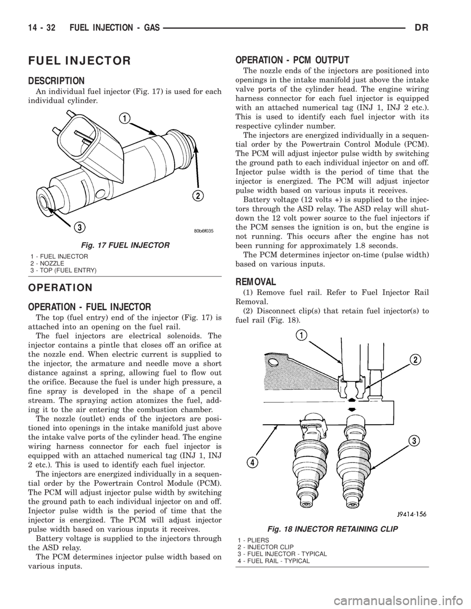
An individual fuel injector (Fig. 17) is used for each
individual cylinder.
OPERATION
OPERATION - FUEL INJECTOR
The top (fuel entry) end of the injector (Fig. 17) is
attached into an opening on the fuel rail.
The fuel injectors are electrical solenoids. The
injector contains a pintle that closes off an orifice at
the nozzle end. When electric current is supplied to
the injector, the armature and needle move a short
distance against a spring, allowing fuel to flow out
the orifice. Because the fuel is under high pressure, a
fine spray is developed in the shape of a pencil
stream. The spraying action atomizes the fuel, add-
ing it to the air entering the combustion chamber.
The nozzle (outlet) ends of the injectors are posi-
tioned into openings in the intake manifold just above
the intake valve ports of the cylinder head. The engine
wiring harness connector for each fuel injector is
equipped with an attached numerical tag (INJ 1, INJ
2 etc.). This is used to identify each fuel injector.
The injectors are energized individually in a sequen-
tial order by the Powertrain Control Module (PCM).
The PCM will adjust injector pulse width by switching
the ground path to each individual injector on and off.
Injector pulse width is the period of time that the
injector is energized. The PCM will adjust injector
pulse width based on various inputs it receives.
Battery voltage is supplied to the injectors through
the ASD relay.
The PCM determines injector pulse width based on
various inputs.
OPERATION - PCM OUTPUT
The nozzle ends of the injectors are positioned into
openings in the intake manifold just above the intake
valve ports of the cylinder head. The engine wiring
harness connector for each fuel injector is equipped
with an attached numerical tag (INJ 1, INJ 2 etc.).
This is used to identify each fuel injector with its
respective cylinder number.
The injectors are energized individually in a sequen-
tial order by the Powertrain Control Module (PCM).
The PCM will adjust injector pulse width by switching
the ground path to each individual injector on and off.
Injector pulse width is the period of time that the
injector is energized. The PCM will adjust injector
pulse width based on various inputs it receives.
Battery voltage (12 volts +) is supplied to the injec-
tors through the ASD relay. The ASD relay will shut-
down the 12 volt power source to the fuel injectors if
the PCM senses the ignition is on, but the engine is
not running. This occurs after the engine has not
been running for approximately 1.8 seconds.
The PCM determines injector on-time (pulse width)
based on various inputs.
REMOVAL
(1) Remove fuel rail. Refer to Fuel Injector Rail
Removal.
(2) Disconnect clip(s) that retain fuel injector(s) to
fuel rail (Fig. 18).
Fig. 17 FUEL INJECTOR
1 - FUEL INJECTOR
2 - NOZZLE
3 - TOP (FUEL ENTRY)
Fig. 18 INJECTOR RETAINING CLIP
1 - PLIERS
2 - INJECTOR CLIP
3 - FUEL INJECTOR - TYPICAL
4 - FUEL RAIL - TYPICAL
14 - 32 FUEL INJECTION - GASDR
Page 1733 of 2895
(2) Install and tighten two mounting bolts (screws)
to 7 N´m (60 in. lbs.) torque.
(3) Install electrical connector.
(4) Install air resonator to throttle body.
5.7L V-8
The IAC motor is not serviceable on the 5.7L V-8
engine.
5.9L V-8
The IAC motor is located on the back of the throt-
tle body (Fig. 22).
(1) Install IAC motor to throttle body.
(2) Install and tighten two mounting bolts (screws)
to 7 N´m (60 in. lbs.) torque.
(3) Install electrical connector.
(4) Install air resonator to throttle body.
8.0L V-10
The IAC motor is located on the back of the throt-
tle body (Fig. 23).
(1) Install IAC motor to throttle body.
(2) Install and tighten two mounting bolts (screws)
to 7 N´m (60 in. lbs.) torque.
(3) Install electrical connector.
(4) Install air cleaner housing to throttle body.
(5) Install 4 air cleaner housing mounting nuts.
Tighten nuts to 11 N´m (96 in. lbs.) torque.
(6) Install air cleaner housing cover.
INTAKE AIR TEMPERATURE
SENSOR
DESCRIPTION
The 2±wire Intake Manifold Air Temperature (IAT)
sensor is installed in the intake manifold with the
sensor element extending into the air stream.
The IAT sensor is a two-wire Negative Thermal
Coefficient (NTC) sensor. Meaning, as intake mani-
fold temperature increases, resistance (voltage) in the
sensor decreases. As temperature decreases, resis-
tance (voltage) in the sensor increases.
OPERATION
The IAT sensor provides an input voltage to the
Powertrain Control Module (PCM) indicating the
density of the air entering the intake manifold based
upon intake manifold temperature. At key-on, a
5±volt power circuit is supplied to the sensor from
the PCM. The sensor is grounded at the PCM
through a low-noise, sensor-return circuit.
The PCM uses this input to calculate the following:
²Injector pulse-width²Adjustment of spark timing (to help prevent
spark knock with high intake manifold air-charge
temperatures)
The resistance values of the IAT sensor is the same
as for the Engine Coolant Temperature (ECT) sensor.
REMOVAL
3.7L V-6
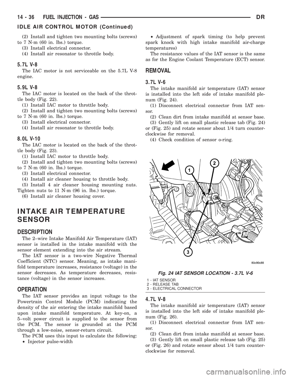
The intake manifold air temperature (IAT) sensor
is installed into the left side of intake manifold ple-
num (Fig. 24).
(1) Disconnect electrical connector from IAT sen-
sor.
(2) Clean dirt from intake manifold at sensor base.
(3) Gently lift on small plastic release tab (Fig. 24)
or (Fig. 25) and rotate sensor about 1/4 turn counter-
clockwise for removal.
(4) Check condition of sensor o-ring.
4.7L V-8
The intake manifold air temperature (IAT) sensor
is installed into the left side of intake manifold ple-
num (Fig. 26).
(1) Disconnect electrical connector from IAT sen-
sor.
(2) Clean dirt from intake manifold at sensor base.
(3) Gently lift on small plastic release tab (Fig. 25)
or (Fig. 26) and rotate sensor about 1/4 turn counter-
clockwise for removal.
Fig. 24 IAT SENSOR LOCATION - 3.7L V-6
1 - IAT SENSOR
2 - RELEASE TAB
3 - ELECTRICAL CONNECTOR
14 - 36 FUEL INJECTION - GASDR
IDLE AIR CONTROL MOTOR (Continued)
Page 1736 of 2895
(1) Install sensor to intake manifold. Tighten to
12±15 N´m (110±130 in. lbs.) torque.
(2) Install electrical connector.
MAP SENSOR
DESCRIPTION
3.7L V-6
The Manifold Absolute Pressure (MAP) sensor is
mounted into the front of the intake manifold with 2
screws.
4.7L V-8
The Manifold Absolute Pressure (MAP) sensor is
mounted into the front of the intake manifold with 2
screws.
5.7L V-8
The Manifold Absolute Pressure (MAP) sensor is
mounted to the front of the intake manifold air ple-
num box.
5.9L V-8
The Manifold Absolute Pressure (MAP) sensor is
mounted to the front of the throttle body with 2
screws.
8.0L V-10
The Manifold Absolute Pressure (MAP) sensor is
mounted into the right side of the intake manifold.
OPERATION
The MAP sensor is used as an input to the Power-
train Control Module (PCM). It contains a silicon
based sensing unit to provide data on the manifold
vacuum that draws the air/fuel mixture into the com-
bustion chamber. The PCM requires this information
to determine injector pulse width and spark advance.
When manifold absolute pressure (MAP) equals
Barometric pressure, the pulse width will be at max-
imum.
A 5 volt reference is supplied from the PCM and
returns a voltage signal to the PCM that reflects
manifold pressure. The zero pressure reading is 0.5V
and full scale is 4.5V. For a pressure swing of 0±15
psi, the voltage changes 4.0V. To operate the sensor,
it is supplied a regulated 4.8 to 5.1 volts. Ground is
provided through the low-noise, sensor return circuit
at the PCM.
The MAP sensor input is the number one contrib-
utor to fuel injector pulse width. The most important
function of the MAP sensor is to determine baromet-
ric pressure. The PCM needs to know if the vehicle is
at sea level or at a higher altitude, because the airdensity changes with altitude. It will also help to cor-
rect for varying barometric pressure. Barometric
pressure and altitude have a direct inverse correla-
tion; as altitude goes up, barometric goes down. At
key-on, the PCM powers up and looks at MAP volt-
age, and based upon the voltage it sees, it knows the
current barometric pressure (relative to altitude).
Once the engine starts, the PCM looks at the voltage
again, continuously every 12 milliseconds, and com-
pares the current voltage to what it was at key-on.
The difference between current voltage and what it
was at key-on, is manifold vacuum.
During key-on (engine not running) the sensor
reads (updates) barometric pressure. A normal range
can be obtained by monitoring a known good sensor.
As the altitude increases, the air becomes thinner
(less oxygen). If a vehicle is started and driven to a
very different altitude than where it was at key-on,
the barometric pressure needs to be updated. Any
time the PCM sees Wide Open Throttle (WOT), based
upon Throttle Position Sensor (TPS) angle and RPM,
it will update barometric pressure in the MAP mem-
ory cell. With periodic updates, the PCM can make
its calculations more effectively.
The PCM uses the MAP sensor input to aid in cal-
culating the following:
²Manifold pressure
²Barometric pressure
²Engine load
²Injector pulse-width
²Spark-advance programs
²Shift-point strategies (certain automatic trans-
missions only)
²Idle speed
²Decel fuel shutoff
The MAP sensor signal is provided from a single
piezoresistive element located in the center of a dia-
phragm. The element and diaphragm are both made
of silicone. As manifold pressure changes, the dia-
phragm moves causing the element to deflect, which
stresses the silicone. When silicone is exposed to
stress, its resistance changes. As manifold vacuum
increases, the MAP sensor input voltage decreases
proportionally. The sensor also contains electronics
that condition the signal and provide temperature
compensation.
The PCM recognizes a decrease in manifold pres-
sure by monitoring a decrease in voltage from the
reading stored in the barometric pressure memory
cell. The MAP sensor is a linear sensor; meaning as
pressure changes, voltage changes proportionately.
The range of voltage output from the sensor is usu-
ally between 4.6 volts at sea level to as low as 0.3
volts at 26 in. of Hg. Barometric pressure is the pres-
sure exerted by the atmosphere upon an object. At
sea level on a standard day, no storm, barometric
DRFUEL INJECTION - GAS 14 - 39
INTAKE AIR TEMPERATURE SENSOR (Continued)
Page 1740 of 2895
OXYGEN SENSOR
DESCRIPTION
The Oxygen Sensors (O2S) are attached to, and
protrude into the vehicle exhaust system. Depending
on the engine or emission package, the vehicle may
use a total of either 2 or 4 sensors.
Federal Emission Packages :Two sensors are
used: upstream (referred to as 1/1) and downstream
(referred to as 1/2). With this emission package, the
upstream sensor (1/1) is located just before the main
catalytic convertor. The downstream sensor (1/2) is
located just after the main catalytic convertor.
California Emission Packages:On this emis-
sions package, 4 sensors are used: 2 upstream
(referred to as 1/1 and 2/1) and 2 downstream
(referred to as 1/2 and 2/2). With this emission pack-
age, the right upstream sensor (2/1) is located in the
right exhaust downpipe just before the mini-catalytic
convertor. The left upstream sensor (1/1) is located in
the left exhaust downpipe just before the mini-cata-
lytic convertor. The right downstream sensor (2/2) is
located in the right exhaust downpipe just after the
mini-catalytic convertor, and before the main cata-
lytic convertor. The left downstream sensor (1/2) is
located in the left exhaust downpipe just after the
mini-catalytic convertor, and before the main cata-
lytic convertor.
OPERATION
An O2 sensor is a galvanic battery that provides
the PCM with a voltage signal (0-1 volt) inversely
proportional to the amount of oxygen in the exhaust.
In other words, if the oxygen content is low, the volt-
age output is high; if the oxygen content is high the
output voltage is low. The PCM uses this information
to adjust injector pulse-width to achieve the
14.7±to±1 air/fuel ratio necessary for proper engine
operation and to control emissions.
The O2 sensor must have a source of oxygen from
outside of the exhaust stream for comparison. Cur-
rent O2 sensors receive their fresh oxygen (outside
air) supply through the O2 sensor case housing.
Four wires (circuits) are used on each O2 sensor: a
12±volt feed circuit for the sensor heating element; a
ground circuit for the heater element; a low-noise
sensor return circuit to the PCM, and an input cir-
cuit from the sensor back to the PCM to detect sen-
sor operation.
Oxygen Sensor Heater Relay - 5.9L/8.0L:If 4
oxygen sensors are used, a separate heater relay is
used to supply voltage to the sensors heating ele-
ments for only the 1/2 and 2/2 downstream sensors.
Voltage for the other 2 sensor heating elements is
supplied directly from the Powertrain Control Mod-ule (PCM) through a Pulse Width Module (PWM)
method.
Pulse Width Module (PWM) - 5.9L/8.0L:Voltage
to the O2 sensor heating elements is supplied
directly from the Powertrain Control Module (PCM)
through two separate Pulse Width Module (PWM)
low side drivers. PWM is used on both the upstream
and downstream O2 sensors if equipped with a Fed-
eral Emissions Package, and only on the 2 upstream
sensors (1/1 and 2/1) if equipped with a California
Emissions Package. The main objective for a PWM
driver is to avoid overheating of the O2 sensor heater
element. With exhaust temperatures increasing with
time and engine speed, it's not required to have a
full-voltage duty-cycle on the O2 heater elements.
To avoid the large simultaneous current surge
needed to operate all 4 sensors, power is delayed to
the 2 downstream heater elements by the PCM for
approximately 2 seconds.
Oxygen Sensor Heater Elements:
The O2 sensor uses a Positive Thermal Co-efficient
(PTC) heater element. As temperature increases,
resistance increases. At ambient temperatures
around 70ÉF, the resistance of the heating element is
approximately 13 ohms. As the sensor's temperature
increases, resistance in the heater element increases.
This allows the heater to maintain the optimum
operating temperature of approximately 930É-1100ÉF
(500É-600É C). Although the sensors operate the
same, there are physical differences, due to the envi-
ronment that they operate in, that keep them from
being interchangeable.
Maintaining correct sensor temperature at all
times allows the system to enter into closed loop
operation sooner. Also, it allows the system to remain
in closed loop operation during periods of extended
idle.
In Closed Loop operation, the PCM monitors cer-
tain O2 sensor input(s) along with other inputs, and
adjusts the injector pulse width accordingly. During
Open Loop operation, the PCM ignores the O2 sensor
input. The PCM adjusts injector pulse width based
on preprogrammed (fixed) values and inputs from
other sensors.
Upstream Sensor - Federal Emissions Pack-
age :The upstream sensor (1/1) provides an input
voltage to the PCM. The input tells the PCM the oxy-
gen content of the exhaust gas. The PCM uses this
information to fine tune fuel delivery to maintain the
correct oxygen content at the downstream oxygen
sensor. The PCM will change the air/fuel ratio until
the upstream sensor inputs a voltage that the PCM
has determined will make the downstream sensor
output (oxygen content) correct.
The upstream oxygen sensor also provides an input
to determine catalytic convertor efficiency.
DRFUEL INJECTION - GAS 14 - 43
Page 1750 of 2895
The PCM supplies approximately 5 volts to the
TPS. The TPS output voltage (input signal to the
PCM) represents the throttle blade position. The
PCM receives an input signal voltage from the TPS.
This will vary in an approximate range of from .26
volts at minimum throttle opening (idle), to 4.49 volts
at wide open throttle. Along with inputs from other
sensors, the PCM uses the TPS input to determine
current engine operating conditions. In response to
engine operating conditions, the PCM will adjust fuel
injector pulse width and ignition timing.
The PCM needs to identify the actions and position
of the throttle blade at all times. This information is
needed to assist in performing the following calcula-
tions:
²Ignition timing advance
²Fuel injection pulse-width
²Idle (learned value or minimum TPS)
²Off-idle (0.06 volt)
²Wide Open Throttle (WOT) open loop (2.608
volts above learned idle voltage)
²Deceleration fuel lean out
²Fuel cutoff during cranking at WOT (2.608 volts
above learned idle voltage)
²A/C WOT cutoff (certain automatic transmis-
sions only)
REMOVAL
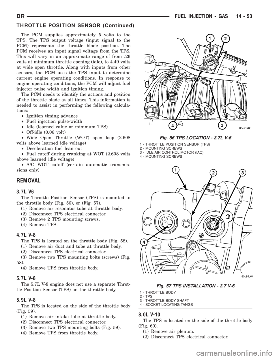
3.7L V6
The Throttle Position Sensor (TPS) is mounted to
the throttle body (Fig. 56), or (Fig. 57).
(1) Remove air resonator tube at throttle body.
(2) Disconnect TPS electrical connector.
(3) Remove 2 TPS mounting screws.
(4) Remove TPS.
4.7L V-8
The TPS is located on the throttle body (Fig. 58).
(1) Remove air duct and tube at throttle body.
(2) Disconnect TPS electrical connector.
(3) Remove two TPS mounting bolts (screws) (Fig.
58).
(4) Remove TPS from throttle body.
5.7L V-8
The 5.7L V-8 engine does not use a separate Throt-
tle Position Sensor (TPS) on the throttle body.
5.9L V-8
The TPS is located on the side of the throttle body
(Fig. 59).
(1) Remove air intake tube at throttle body.
(2) Disconnect TPS electrical connector.
(3) Remove two TPS mounting bolts (Fig. 59).
(4) Remove TPS from throttle body.
8.0L V-10
The TPS is located on the side of the throttle body
(Fig. 60).
(1) Remove air plenum.
(2) Disconnect TPS electrical connector.
Fig. 56 TPS LOCATION - 3.7L V-6
1 - THROTTLE POSITION SENSOR (TPS)
2 - MOUNTING SCREWS
3 - IDLE AIR CONTROL MOTOR (IAC)
4 - MOUNTING SCREWS
Fig. 57 TPS INSTALLATION - 3.7 V-6
1 - THROTTLE BODY
2 - TPS
3 - THROTTLE BODY SHAFT
4 - SOCKET LOCATING TANGS
DRFUEL INJECTION - GAS 14 - 53
THROTTLE POSITION SENSOR (Continued)
Page 2092 of 2895
ASSEMBLY
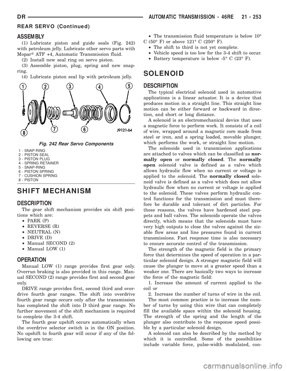
(1) Lubricate piston and guide seals (Fig. 242)
with petroleum jelly. Lubricate other servo parts with
MopartATF +4, Automatic Transmission fluid.
(2) Install new seal ring on servo piston.
(3) Assemble piston, plug, spring and new snap-
ring.
(4) Lubricate piston seal lip with petroleum jelly.
SHIFT MECHANISM
DESCRIPTION
The gear shift mechanism provides six shift posi-
tions which are:
²PARK (P)
²REVERSE (R)
²NEUTRAL (N)
²DRIVE (D)
²Manual SECOND (2)
²Manual LOW (1)
OPERATION
Manual LOW (1) range provides first gear only.
Overrun braking is also provided in this range. Man-
ual SECOND (2) range provides first and second gear
only.
DRIVE range provides first, second third and over-
drive fourth gear ranges. The shift into overdrive
fourth gear range occurs only after the transmission
has completed the shift into D third gear range. No
further movement of the shift mechanism is required
to complete the 3-4 shift.
The fourth gear upshift occurs automatically when
the overdrive selector switch is in the ON position.
No upshift to fourth gear will occur if any of the fol-
lowing are true:²The transmission fluid temperature is below 10É
C (50É F) or above 121É C (250É F).
²The shift to third is not yet complete.
²Vehicle speed is too low for the 3-4 shift to occur.
²Battery temperature is below -5É C (23É F).
SOLENOID
DESCRIPTION
The typical electrical solenoid used in automotive
applications is a linear actuator. It is a device that
produces motion in a straight line. This straight line
motion can be either forward or backward in direc-
tion, and short or long distance.
A solenoid is an electromechanical device that uses
a magnetic force to perform work. It consists of a coil
of wire, wrapped around a magnetic core made from
steel or iron, and a spring loaded, movable plunger,
which performs the work, or straight line motion.
The solenoids used in transmission applications
are attached to valves which can be classified asnor-
mally openornormally closed. Thenormally
opensolenoid valve is defined as a valve which
allows hydraulic flow when no current or voltage is
applied to the solenoid. Thenormally closedsole-
noid valve is defined as a valve which does not allow
hydraulic flow when no current or voltage is applied
to the solenoid. These valves perform hydraulic con-
trol functions for the transmission and must there-
fore be durable and tolerant of dirt particles. For
these reasons, the valves have hardened steel pop-
pets and ball valves. The solenoids operate the valves
directly, which means that the solenoids must have
very high outputs to close the valves against the siz-
able flow areas and line pressures found in current
transmissions. Fast response time is also necessary
to ensure accurate control of the transmission.
The strength of the magnetic field is the primary
force that determines the speed of operation in a par-
ticular solenoid design. A stronger magnetic field will
cause the plunger to move at a greater speed than a
weaker one. There are basically two ways to increase
the force of the magnetic field:
1. Increase the amount of current applied to the
coil or
2. Increase the number of turns of wire in the coil.
The most common practice is to increase the num-
ber of turns by using thin wire that can completely
fill the available space within the solenoid housing.
The strength of the spring and the length of the
plunger also contribute to the response speed possi-
ble by a particular solenoid design.
A solenoid can also be described by the method by
which it is controlled. Some of the possibilities
include variable force, pulse-width modulated, con-
Fig. 242 Rear Servo Components
1 - SNAP-RING
2 - PISTON SEAL
3 - PISTON PLUG
4 - SPRING RETAINER
5 - SNAP-RING
6 - PISTON SPRING
7 - CUSHION SPRING
8 - PISTON
DRAUTOMATIC TRANSMISSION - 46RE 21 - 253
REAR SERVO (Continued)
Page 2093 of 2895
stant ON, or duty cycle. The variable force and pulse-
width modulated versions utilize similar methods to
control the current flow through the solenoid to posi-
tion the solenoid plunger at a desired position some-
where between full ON and full OFF. The constant
ON and duty cycled versions control the voltage
across the solenoid to allow either full flow or no flow
through the solenoid's valve.
OPERATION
When an electrical current is applied to the sole-
noid coil, a magnetic field is created which produces
an attraction to the plunger, causing the plunger to
move and work against the spring pressure and the
load applied by the fluid the valve is controlling. The
plunger is normally directly attached to the valve
which it is to operate. When the current is removed
from the coil, the attraction is removed and the
plunger will return to its original position due to
spring pressure.
The plunger is made of a conductive material and
accomplishes this movement by providing a path for
the magnetic field to flow. By keeping the air gap
between the plunger and the coil to the minimum
necessary to allow free movement of the plunger, the
magnetic field is maximized.
SPEED SENSOR
DESCRIPTION
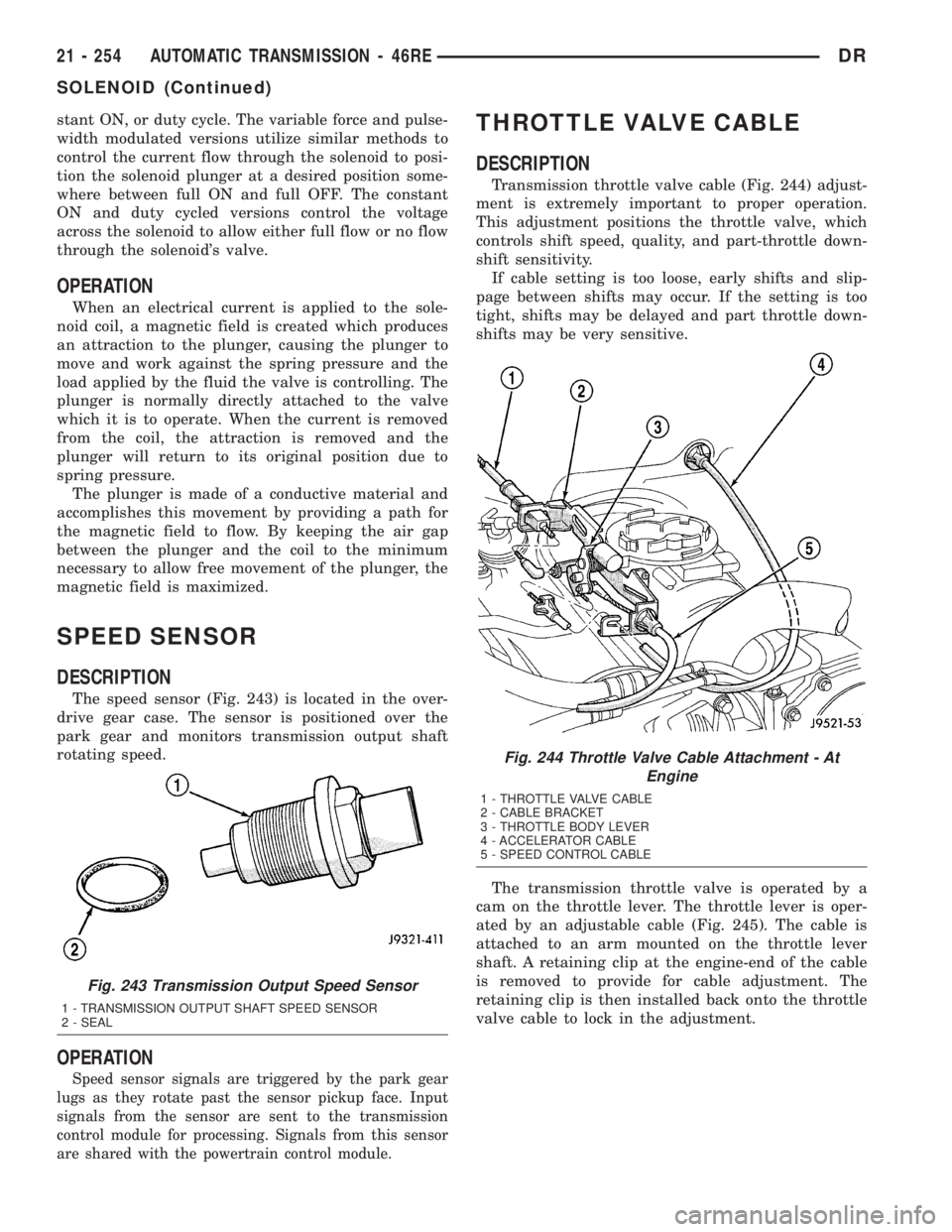
The speed sensor (Fig. 243) is located in the over-
drive gear case. The sensor is positioned over the
park gear and monitors transmission output shaft
rotating speed.
OPERATION
Speed sensor signals are triggered by the park gear
lugs as they rotate past the sensor pickup face. Input
signals from the sensor are sent to the transmission
control module for processing. Signals from this sensor
are shared with the powertrain control module.
THROTTLE VALVE CABLE
DESCRIPTION
Transmission throttle valve cable (Fig. 244) adjust-
ment is extremely important to proper operation.
This adjustment positions the throttle valve, which
controls shift speed, quality, and part-throttle down-
shift sensitivity.
If cable setting is too loose, early shifts and slip-
page between shifts may occur. If the setting is too
tight, shifts may be delayed and part throttle down-
shifts may be very sensitive.
The transmission throttle valve is operated by a
cam on the throttle lever. The throttle lever is oper-
ated by an adjustable cable (Fig. 245). The cable is
attached to an arm mounted on the throttle lever
shaft. A retaining clip at the engine-end of the cable
is removed to provide for cable adjustment. The
retaining clip is then installed back onto the throttle
valve cable to lock in the adjustment.
Fig. 243 Transmission Output Speed Sensor
1 - TRANSMISSION OUTPUT SHAFT SPEED SENSOR
2 - SEAL
Fig. 244 Throttle Valve Cable Attachment - At
Engine
1 - THROTTLE VALVE CABLE
2 - CABLE BRACKET
3 - THROTTLE BODY LEVER
4 - ACCELERATOR CABLE
5 - SPEED CONTROL CABLE
21 - 254 AUTOMATIC TRANSMISSION - 46REDR
SOLENOID (Continued)