2003 DODGE RAM engine
[x] Cancel search: enginePage 1441 of 2895
SPECIAL TOOLS
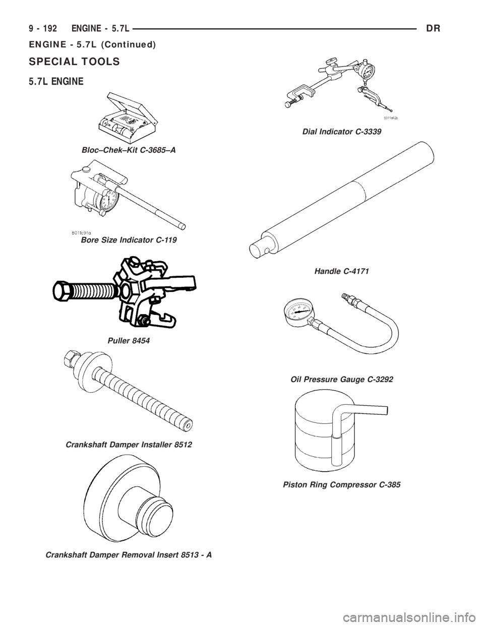
5.7L ENGINE
Bloc±Chek±Kit C-3685±A
Bore Size Indicator C-119
Puller 8454
Crankshaft Damper Installer 8512
Crankshaft Damper Removal Insert 8513 - A
Dial Indicator C-3339
Handle C-4171
Oil Pressure Gauge C-3292
Piston Ring Compressor C-385
9 - 192 ENGINE - 5.7LDR
ENGINE - 5.7L (Continued)
Page 1442 of 2895
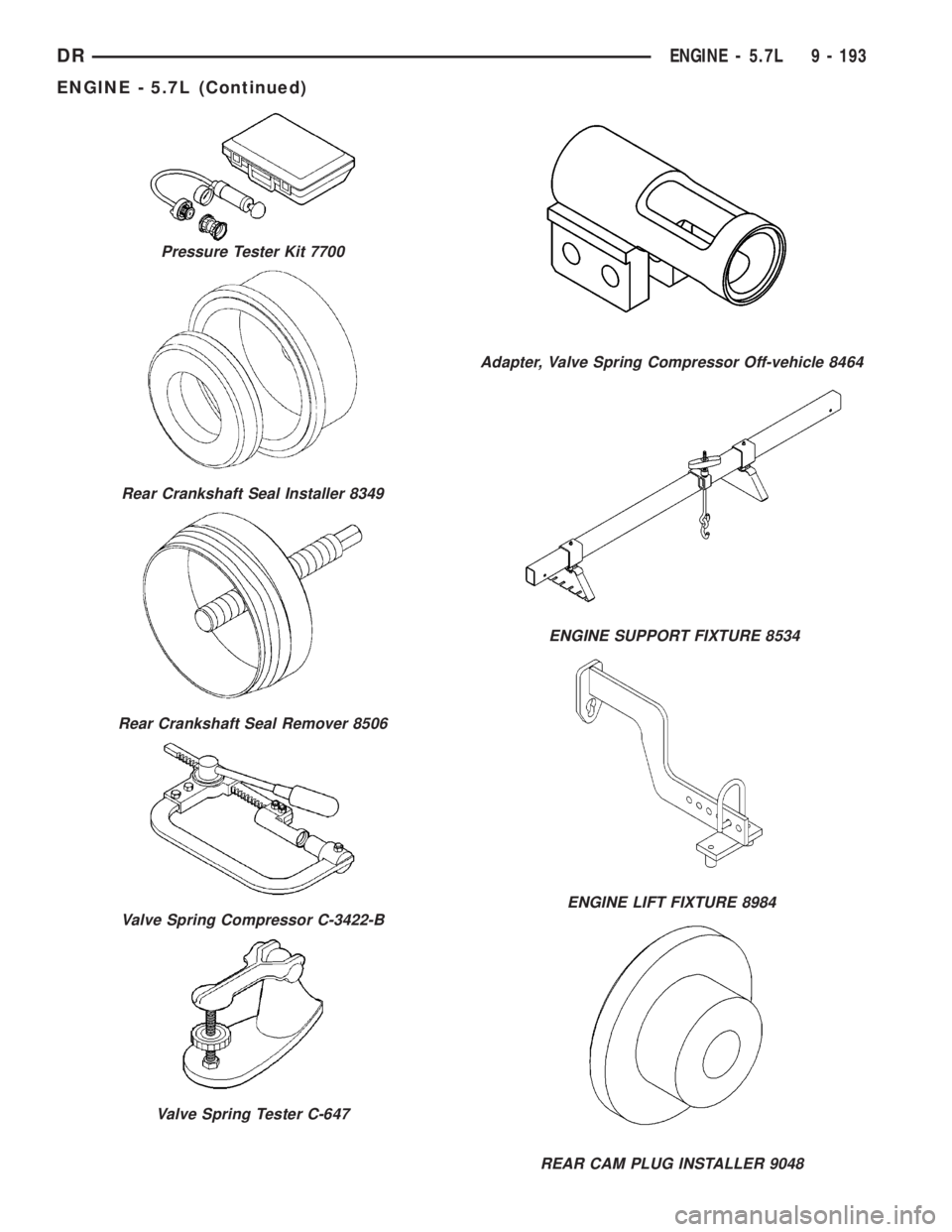
Pressure Tester Kit 7700
Rear Crankshaft Seal Installer 8349
Rear Crankshaft Seal Remover 8506
Valve Spring Compressor C-3422-B
Valve Spring Tester C-647
Adapter, Valve Spring Compressor Off-vehicle 8464
ENGINE SUPPORT FIXTURE 8534
ENGINE LIFT FIXTURE 8984
REAR CAM PLUG INSTALLER 9048
DRENGINE - 5.7L 9 - 193
ENGINE - 5.7L (Continued)
Page 1443 of 2895
AIR INTAKE SYSTEM
REMOVAL
Filter Element Only
Housing removal is not necessary for element (fil-
ter) replacement.
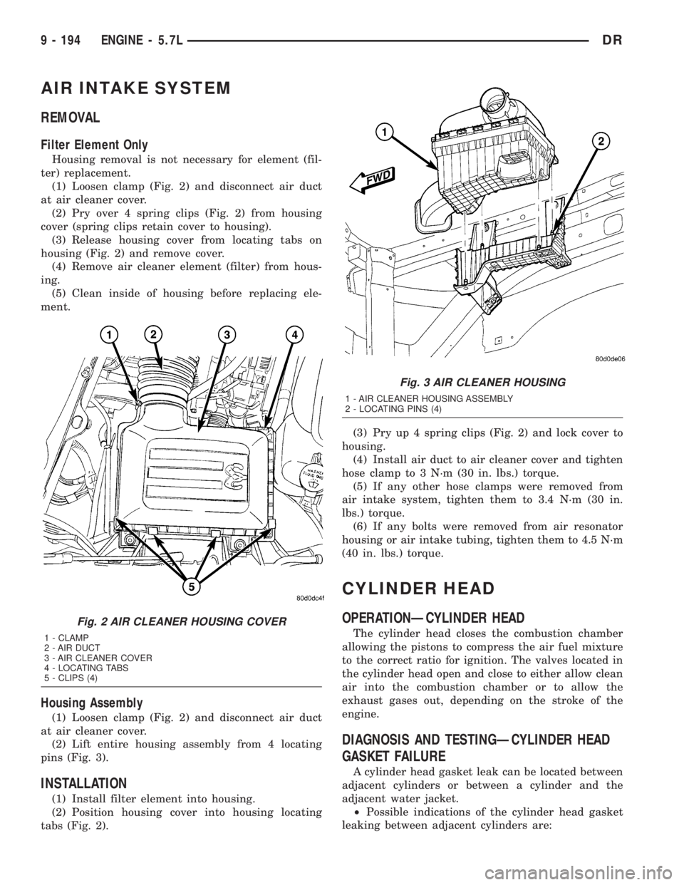
(1) Loosen clamp (Fig. 2) and disconnect air duct
at air cleaner cover.
(2) Pry over 4 spring clips (Fig. 2) from housing
cover (spring clips retain cover to housing).
(3) Release housing cover from locating tabs on
housing (Fig. 2) and remove cover.
(4) Remove air cleaner element (filter) from hous-
ing.
(5) Clean inside of housing before replacing ele-
ment.
Housing Assembly
(1) Loosen clamp (Fig. 2) and disconnect air duct
at air cleaner cover.
(2) Lift entire housing assembly from 4 locating
pins (Fig. 3).
INSTALLATION
(1) Install filter element into housing.
(2) Position housing cover into housing locating
tabs (Fig. 2).(3) Pry up 4 spring clips (Fig. 2) and lock cover to
housing.
(4) Install air duct to air cleaner cover and tighten
hose clamp to 3 N´m (30 in. lbs.) torque.
(5) If any other hose clamps were removed from
air intake system, tighten them to 3.4 N´m (30 in.
lbs.) torque.
(6) If any bolts were removed from air resonator
housing or air intake tubing, tighten them to 4.5 N´m
(40 in. lbs.) torque.
CYLINDER HEAD
OPERATIONÐCYLINDER HEAD
The cylinder head closes the combustion chamber
allowing the pistons to compress the air fuel mixture
to the correct ratio for ignition. The valves located in
the cylinder head open and close to either allow clean
air into the combustion chamber or to allow the
exhaust gases out, depending on the stroke of the
engine.
DIAGNOSIS AND TESTINGÐCYLINDER HEAD
GASKET FAILURE
A cylinder head gasket leak can be located between
adjacent cylinders or between a cylinder and the
adjacent water jacket.
²Possible indications of the cylinder head gasket
leaking between adjacent cylinders are:
Fig. 2 AIR CLEANER HOUSING COVER
1 - CLAMP
2 - AIR DUCT
3 - AIR CLEANER COVER
4 - LOCATING TABS
5 - CLIPS (4)
Fig. 3 AIR CLEANER HOUSING
1 - AIR CLEANER HOUSING ASSEMBLY
2 - LOCATING PINS (4)
9 - 194 ENGINE - 5.7LDR
Page 1444 of 2895
þ Loss of engine power
þ Engine misfiring
þ Poor fuel economy
²Possible indications of the cylinder head gasket
leaking between a cylinder and an adjacent water
jacket are:
þ Engine overheating
þ Loss of coolant
þ Excessive steam (white smoke) emitting from
exhaust
þ Coolant foaming
CYLINDER-TO-CYLINDER LEAKAGE TEST
To determine if an engine cylinder head gasket is
leaking between adjacent cylinders, follow the proce-
dures in Cylinder Compression Pressure Test in this
section. An engine cylinder head gasket leaking
between adjacent cylinders will result in approxi-
mately a 50±70% reduction in compression pressure.
CYLINDER-TO-WATER JACKET LEAKAGE TEST
WARNING: USE EXTREME CAUTION WHEN THE
ENGINE IS OPERATING WITH COOLANT PRES-
SURE CAP REMOVED.
VISUAL TEST METHOD
With the engine cool, remove the coolant pressure
cap. Start the engine and allow it to warm up until
thermostat opens.
If a large combustion/compression pressure leak
exists, bubbles will be visible in the coolant.
COOLING SYSTEM TESTER METHOD
WARNING: WITH COOLING SYSTEM TESTER IN
PLACE, PRESSURE WILL BUILD UP FAST. EXCES-
SIVE PRESSURE BUILT UP, BY CONTINUOUS
ENGINE OPERATION, MUST BE RELEASED TO A
SAFE PRESSURE POINT. NEVER PERMIT PRES-
SURE TO EXCEED 138 kPa (20 psi).
Install Cooling System Tester 7700 or equivalent to
pressure cap neck. Start the engine and observe the
tester's pressure gauge. If gauge pulsates with every
power stroke of a cylinder a combustion pressure
leak is evident.
CHEMICAL TEST METHOD
Combustion leaks into the cooling system can also
be checked by using Bloc-Chek Kit C-3685-A or
equivalent. Perform test following the procedures
supplied with the tool kit.
REMOVAL
(1) Disconnect the battery negative cable.
(2) Drain cooling system.
(3) Remove the air cleaner resonator and duct
work.
(4) Remove the generator.
(5) Remove closed crankcase ventilation system.
(6) Disconnect the evaporation control system.
(7) Perform the Fuel System Pressure Release pro-
cedure (Refer to 14 - FUEL SYSTEM/FUEL DELIV-
ERY - STANDARD PROCEDURE). Disconnect the
fuel supply line (Refer to 14 - FUEL SYSTEM/FUEL
DELIVERY/QUICK CONNECT FITTING - STAN-
DARD PROCEDURE).
(8) Disconnect heater hoses.
(9) Remove cylinder head covers and gaskets.
(10) Remove intake manifold and throttle body as
an assembly.
(11) Remove rocker arm assemblies and push rods.
Identify to ensure installation in original locations.
(12) Remove the head bolts from each cylinder
head and remove cylinder heads. Discard the cylin-
der head gasket.
CLEANING
Clean all surfaces of cylinder block and cylinder
heads.
Clean cylinder block front and rear gasket surfaces
using a suitable solvent.
INSPECTION
(1) Inspect the cylinder head for out-of-flatness,
using a straightedge and a feeler gauge. If tolerances
exceed 0.0508 mm (0.002 in.) replace the cylinder
head.
(2) Inspect the valve seats for damage. Service the
valve seats as necessary.
(3) Inspect the valve guides for wear, cracks or
looseness. If either condition exist, replace the cylin-
der head.
(4) Inspect pushrods. Replace worn or bent push-
rods.
INSTALLATION
(1) Clean all surfaces of cylinder block and cylin-
der heads.
(2) Clean cylinder block front and rear gasket sur-
faces using a suitable solvent.
CAUTION: The head gaskets are not interchange-
able between left and right sides. They are marked
ªLº and ªRº to indicate left and right sides.
(3) Position new cylinder head gaskets onto the
cylinder block.
DRENGINE - 5.7L 9 - 195
CYLINDER HEAD (Continued)
Page 1445 of 2895
CAUTION: The head gaskets are marked ªTOPº to
indicate which side goes up.
(4) Position cylinder heads onto head gaskets and
cylinder block.
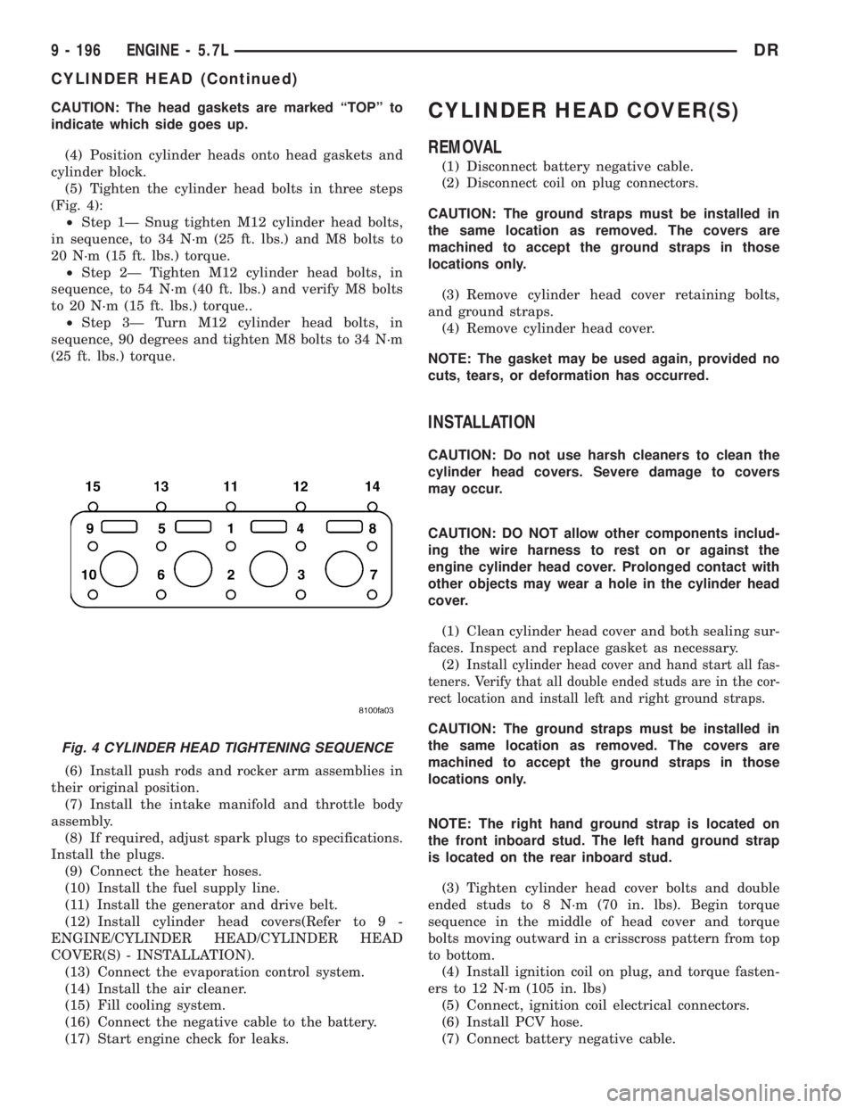
(5) Tighten the cylinder head bolts in three steps
(Fig. 4):
²Step 1Ð Snug tighten M12 cylinder head bolts,
in sequence, to 34 N´m (25 ft. lbs.) and M8 bolts to
20 N´m (15 ft. lbs.) torque.
²Step 2Ð Tighten M12 cylinder head bolts, in
sequence, to 54 N´m (40 ft. lbs.) and verify M8 bolts
to 20 N´m (15 ft. lbs.) torque..
²Step 3Ð Turn M12 cylinder head bolts, in
sequence, 90 degrees and tighten M8 bolts to 34 N´m
(25 ft. lbs.) torque.
(6) Install push rods and rocker arm assemblies in
their original position.
(7) Install the intake manifold and throttle body
assembly.
(8) If required, adjust spark plugs to specifications.
Install the plugs.
(9) Connect the heater hoses.
(10) Install the fuel supply line.
(11) Install the generator and drive belt.
(12) Install cylinder head covers(Refer to 9 -
ENGINE/CYLINDER HEAD/CYLINDER HEAD
COVER(S) - INSTALLATION).
(13) Connect the evaporation control system.
(14) Install the air cleaner.
(15) Fill cooling system.
(16) Connect the negative cable to the battery.
(17) Start engine check for leaks.CYLINDER HEAD COVER(S)
REMOVAL
(1) Disconnect battery negative cable.
(2) Disconnect coil on plug connectors.
CAUTION: The ground straps must be installed in
the same location as removed. The covers are
machined to accept the ground straps in those
locations only.
(3) Remove cylinder head cover retaining bolts,
and ground straps.
(4) Remove cylinder head cover.
NOTE: The gasket may be used again, provided no
cuts, tears, or deformation has occurred.
INSTALLATION
CAUTION: Do not use harsh cleaners to clean the
cylinder head covers. Severe damage to covers
may occur.
CAUTION: DO NOT allow other components includ-
ing the wire harness to rest on or against the
engine cylinder head cover. Prolonged contact with
other objects may wear a hole in the cylinder head
cover.
(1) Clean cylinder head cover and both sealing sur-
faces. Inspect and replace gasket as necessary.
(2)
Install cylinder head cover and hand start all fas-
teners. Verify that all double ended studs are in the cor-
rect location and install left and right ground straps.
CAUTION: The ground straps must be installed in
the same location as removed. The covers are
machined to accept the ground straps in those
locations only.
NOTE: The right hand ground strap is located on
the front inboard stud. The left hand ground strap
is located on the rear inboard stud.
(3) Tighten cylinder head cover bolts and double
ended studs to 8 N´m (70 in. lbs). Begin torque
sequence in the middle of head cover and torque
bolts moving outward in a crisscross pattern from top
to bottom.
(4) Install ignition coil on plug, and torque fasten-
ers to 12 N´m (105 in. lbs)
(5) Connect, ignition coil electrical connectors.
(6) Install PCV hose.
(7) Connect battery negative cable.
Fig. 4 CYLINDER HEAD TIGHTENING SEQUENCE
9 - 196 ENGINE - 5.7LDR
CYLINDER HEAD (Continued)
Page 1446 of 2895
INTAKE/EXHAUST VALVES &
SEATS
DESCRIPTION
DESCRIPTION - VALVE GUIDES
The valve guides are made of powered metal and
are pressed into the cylinder head. The guides are
not replaceable or serviceable, and valve guide ream-
ing is not recommended. If the guides are worn
beyond acceptable limits, replace the cylinder heads.
DESCRIPTION
Both the intake and exhaust valves are made of
steel. The intake valve is 50.93 mm (2.00 inches) in
diameter and the exhaust valve is 39.53 mm (1.55
inches) in diameter. All valves use three bead lock
keepers to retain the springs and promote valve rota-
tion.
STANDARD PROCEDURE - REFACING
NOTE: Valve seats that are worn or burned can be
reworked, provided that correct angle and seat
width are maintained. Otherwise the cylinder head
must be replaced.
NOTE: When refacing valves and valve seats, it is
important that the correct size valve guide pilot be
used for reseating stones. A true and complete sur-
face must be obtained.
(1) Using a suitable dial indicator measure the
center of the valve seat Total run out must not
exceed 0.051 mm (0.002 in).
(2) Apply a small amount of Prussian blue to the
valve seat, insert the valve into the cylinder head,
while applying light pressure on the valve rotate the
valve. Remove the valve and examine the valve face.
If the blue is transferred below the top edge of the
valve face, lower the valve seat using a 15 degree
stone. If the blue is transferred to the bottom edge of
the valve face, raise the valve seat using a 65 degree
stone.
(3) When the seat is properly positioned the width
of the intake seat must be 1.018 - 1.62 mm (0.0464 -
0.0637 in.) and the exhaust seat must be 1.48 - 1.92
mm (0.058 - 0.075 in.).
(4) Check the valve spring installed height after
refacing the valve and seat. The installed height for
both intake and exhaust valve springs must not
exceed 46.0 mm (1.81 in.).
VALVE FACE AND VALVE SEAT ANGLE CHART
DESCRIPTION SPECIFICATION
SEAT WIDTH
INTAKE 1.018 - 1.62 mm
(0.0464 - 0.0637 in.)
EXHAUST 1.48 - 1.92 mm
(0.058 - 0.075 in.)
FACE ANGLE
(INT. AND EXT.) 45É - 45
1¤2É
SEAT ANGLE
(INT. AND EXT.) 44
1¤2É - 45É
(5) The valve seat must maintain an angle of 44.5
± 45.0 degrees angle.
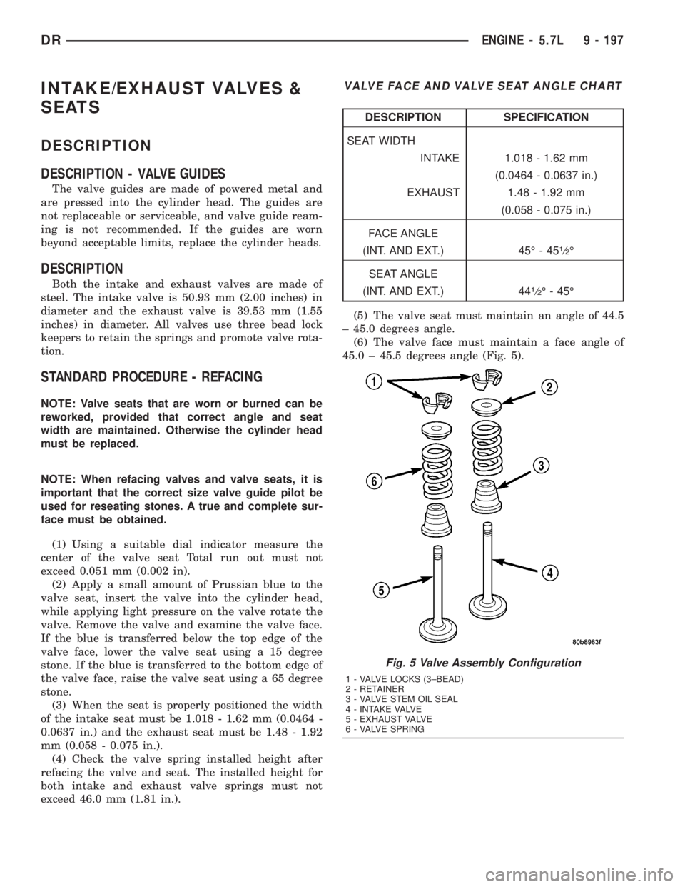
(6) The valve face must maintain a face angle of
45.0 ± 45.5 degrees angle (Fig. 5).
Fig. 5 Valve Assembly Configuration
1 - VALVE LOCKS (3±BEAD)
2 - RETAINER
3 - VALVE STEM OIL SEAL
4 - INTAKE VALVE
5 - EXHAUST VALVE
6 - VALVE SPRING
DRENGINE - 5.7L 9 - 197
Page 1447 of 2895
REMOVAL
(1) Remove the cylinder head (Refer to 9 -
ENGINE/CYLINDER HEAD - REMOVAL).
(2) Compress valve springs using Valve Spring
Compressor Tool special tool # C-3422and adapter
8464.
(3) Remove valve retaining locks, valve spring
retainers, valve stem seals and valve springs.
(4) Before removing valves, remove any burrs from
valve stem lock grooves to prevent damage to the
valve guides. Identify valves to ensure installation in
original location.
INSTALLATION
(1) Clean valves thoroughly. Discard burned,
warped and cracked valves.
(2) Remove carbon and varnish deposits from
inside of valve guides with a reliable guide cleaner.
(3) Measure valve stems for wear. If wear exceeds
0.051 mm (0.002 inch), replace the valve.
(4) Coat valve stems with lubrication oil and insert
them in cylinder head.
(5) If valves or seats are reground, check valve
stem height. If valve is too long, replace cylinder
head.
(6) Install new seals on all valve guides. Install
valve springs and valve retainers.
(7) Compress valve springs with Valve Spring
Compressor Tool special tool # C- 3422and adapter
8464, install locks and release tool. If valves and/or
seats are ground, measure the installed height of
springs. Make sure the measurement is taken from
bottom of spring seat in cylinder head to the bottom
surface of spring retainer.
(8) Install cylinder head (Refer to 9 - ENGINE/
CYLINDER HEAD - INSTALLATION).
ROCKER ARM / ADJUSTER
ASSY
REMOVAL
(1) Remove cylinder head cover.(Refer to 9 -
ENGINE/CYLINDER HEAD/CYLINDER HEAD
COVER(S) - REMOVAL)
(2) Loosen the rocker shafts using the following
sequence:Center, center-left, center-right, left,
right,.
CAUTION: The rocker shaft assemblies are not
interchangeable between intake and exhaust. The
intake rocker arms are marked with an ªIº.(3) Remove the rocker shafts. Note location for
reassembly.
CAUTION: The longer push rods are for the exhaust
side, and the shorter push rods are for intake side.
(4) Remove the pushrods. Note pushrod location
for reassembly.
INSTALLATION
CAUTION: The longer push rods are for the exhaust
side, and the shorter push rods are for intake side.
(1) Install the push rods in the same order as
removed.
CAUTION: Verify that pushrod is installed into
rocker arm and lifter correctly while installing
rocker shaft assembly. Recheck after rocker shaft
has been torqued to specification.
CAUTION: The rocker shaft assemblies are not
interchangeable between intake and exhaust. The
intake rocker arms are marked with the letter ªIº.
(2) Install rocker shaft assemblies in the same
order as removed.
CAUTION: Ensure that hold downs and rocker arms
are not overlapped when torquing bolts.
(3) Tighten the rocker shaft bolts to 22 N´m (195
in. lbs.) torque,using the following sequence:Center,
center-right, center-left, right, left.
CAUTION: DO NOT rotate or crank the engine dur-
ing or immediately after rocker arm installation.
Allow the hydraulic roller tappets adequate time to
bleed down (about 5 minutes).
(4) Install cylinder head cover (Refer to 9 -
ENGINE/CYLINDER HEAD/CYLINDER HEAD
COVER(S) - INSTALLATION).
VALVE STEM SEALS
DESCRIPTION
The valve guide seals are made of rubber and
incorporate an integral steel valve spring seat. The
integral garter spring maintains consistent lubrica-
tion control to the valve stems.
9 - 198 ENGINE - 5.7LDR
INTAKE/EXHAUST VALVES & SEATS (Continued)
Page 1448 of 2895
VALVE SPRINGS
REMOVAL
(1) Disconnect negative battery cable.
(2) Remove air cleaner assembly.
(3) Remove air intake resonator.
(4) Remove spark plug cables.
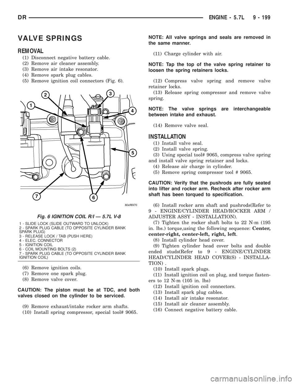
(5) Remove ignition coil connectors (Fig. 6).
(6) Remove ignition coils.
(7) Remove one spark plug.
(8) Remove valve cover.
CAUTION: The piston must be at TDC, and both
valves closed on the cylinder to be serviced.
(9) Remove exhaust/intake rocker arm shafts.
(10) Install spring compressor, special tool# 9065.NOTE: All valve springs and seals are removed in
the same manner.
(11) Charge cylinder with air.
NOTE: Tap the top of the valve spring retainer to
loosen the spring retainers locks.
(12) Compress valve spring and remove valve
retainer locks.
(13) Release spring compressor and remove valve
spring.
NOTE: The valve springs are interchangeable
between intake and exhaust.
(14) Remove valve seal.
INSTALLATION
(1) Install valve seal.
(2) Install valve spring.
(3) Using special tool# 9065, compress valve spring
and install valve spring retainer and locks.
(4) Release air charge in cylinder.
(5) Remove spring compressor tool # 9065.
CAUTION: Verify that the pushrods are fully seated
into lifter and rocker arm. Recheck after rocker arm
shaft has been torqued to specification.
(6) Install rocker arm shaft and pushrods(Refer to
9 - ENGINE/CYLINDER HEAD/ROCKER ARM /
ADJUSTER ASSY - INSTALLATION).
(7) Tighten the rocker shaft bolts to 22 N´m (195
in. lbs.) torque,using the following sequence:Center,
center-right, center-left, right, left.
(8) Install cylinder head cover.
(9) Tighten cylinder head cover bolts and double
ended studs(Refer to 9 - ENGINE/CYLINDER
HEAD/CYLINDER HEAD COVER(S) - INSTALLA-
TION) .
(10) Install spark plugs.
(11) Install ignition coil on plug, and torque fasten-
ers to 12 N´m (105 in. lbs)
(12) Install ignition coil connectors.
(13) Install spark plug cables.
(14) Install air intake resonator.
(15) Install air cleaner assembly.
(16) Connect negative battery cable.
Fig. 6 IGNITION COIL R/I Ð 5.7L V-8
1 - SLIDE LOCK (SLIDE OUTWARD TO UNLOCK)
2 - SPARK PLUG CABLE (TO OPPOSITE CYLINDER BANK
SPARK PLUG)
3 - RELEASE LOCK / TAB (PUSH HERE)
4 - ELEC. CONNECTOR
5 - IGNITION COIL
6 - COIL MOUNTING BOLTS (2)
7 - SPARK PLUG CABLE (TO OPPOSITE CYLINDER BANK
IGNITION COIL)
DRENGINE - 5.7L 9 - 199