2003 DODGE RAM radiator cap
[x] Cancel search: radiator capPage 1547 of 2895
Filter Removal
(1) The housing cover is equipped with spring clips
(Fig. 6) and is hinged with plastic tabs. Unlatch clips
from top of air cleaner housing and tilt housing cover
up for cover removal.
(2) Remove air cleaner element from air cleaner
housing.
INSTALLATION
(1) Before installing new air cleaner element (fil-
ter), clean inside of air cleaner housing.
(2) Position air cleaner cover to tabs on front of air
cleaner housing. Latch spring clips to seal cover to
housing.
CYLINDER HEAD
DESCRIPTION
The cylinder head is constructed of cast iron and is
a one piece cross flow design with four valves per cyl-
inder. The arrangement of two intake and two
exhaust valves per cylinder allows for a centrally
located injector. The cylinder head also includes an
integral intake manifold, an integral thermostat
housing, and a longitudal fuel return rifle, which
exits at the rear of the head. The 24 valve design
also includes integrally cast valve guides and hard-
ened intake and exhaust valve seat inserts.
REMOVAL
(1) Disconnect battery negative cables.
(2) Raise vehicle on hoist.
(3) Drain engine coolant.
(4) Disconnect exhaust pipe from turbocharger
elbow.
(5) Lower vehicle.
(6) Disconnect air inlet temperature/pressure sen-
sor.
(7) Remove air cleaner housing and snorkel from
the vehicle. Cap off turbocharger air inlet to prevent
intrusion of dirt or foreign material.
(8) Disconnect cab heater core supply and return
hoses from the cylinder head and heater pipe.
(9) Disconnect turbocharger oil drain tube at rub-
ber hose connection. Cap off open ports to prevent
intrusion of dirt or foreign material.
(10) Disconnect turbocharger oil supply line at the
turbocharger end. Cap off open ports to prevent
intrusion of dirt or foreign material.
(11) Remove exhaust manifold-to-cylinder head
bolts, spacers, heat shield, retention straps, and cab
heater plumbing. Remove exhaust manifold and tur-
bocharger from the vehicle as an assembly.
(12) Remove cooling fan assembly.
(13) Remove accessory drive belt (Refer to 7 -
COOLING/ACCESSORY DRIVE/DRIVE BELTS -
REMOVAL).
(14) Remove cooling fan support from cylinder
block.
(15) Remove upper generator bolt, loosen lower
generator bolt, and rotate generator away from cylin-
der head.
(16) Disconnect radiator upper hose from the ther-
mostat housing.
(17) Disconnect the Intake Air Temperature, Man-
ifold Air Pressure, and Coolant Temperature sensor
connector.
(18) Remove the engine harness to cylinder head
attaching bolts and P-clips at front of head.
(19) Remove the throttle linkage cover (Fig. 8).
(20) Remove the six (6) accelerator pedal position
sensor assembly-to-cylinder head bracket bolts (Fig.
9) and secure the entire assembly out of the way.
Disconnect the APPS connector (Fig. 10).It is not
necessary to disconnect the cables from the
throttle control assembly.
(21) Remove the intake air grid heater wires from
the grid heater.
(22) Remove engine oil level indicator tube attach-
ing bolt at fuel filter housing bracket and inlet air
connection..
(23) Remove the charge air cooler-to-air inlet hous-
ing pipe.
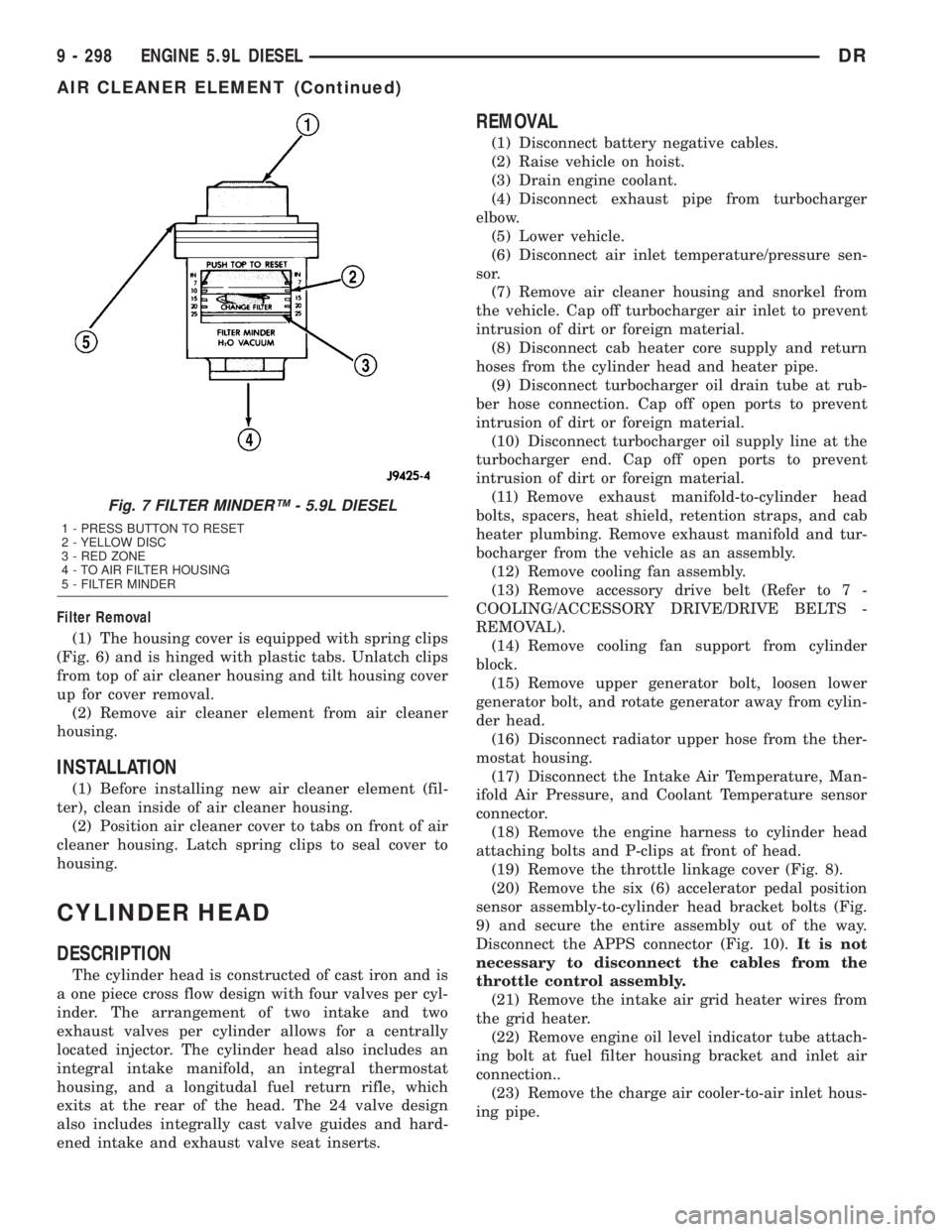
Fig. 7 FILTER MINDERŸ - 5.9L DIESEL
1 - PRESS BUTTON TO RESET
2 - YELLOW DISC
3 - RED ZONE
4 - TO AIR FILTER HOUSING
5 - FILTER MINDER
9 - 298 ENGINE 5.9L DIESELDR
AIR CLEANER ELEMENT (Continued)
Page 1572 of 2895
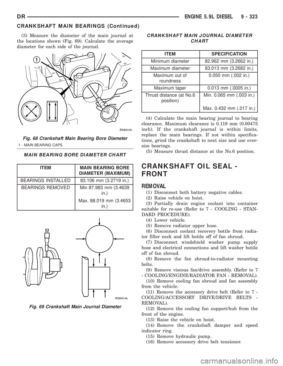
(3) Measure the diameter of the main journal at
the locations shown (Fig. 69). Calculate the average
diameter for each side of the journal.
MAIN BEARING BORE DIAMETER CHART
ITEM MAIN BEARING BORE
DIAMETER (MAXIMUM)
BEARINGS INSTALLED 83.106 mm (3.2719 in.)
BEARINGS REMOVED Min 87.983 mm (3.4639
in.)
Max. 88.019 mm (3.4653
in.)
CRANKSHAFT MAIN JOURNAL DIAMETER
CHART
ITEM SPECIFICATION
Minimum diameter 82.962 mm (3.2662 in.)
Maximum diameter 83.013 mm (3.2682 in.)
Maximum out of
roundness0.050 mm (.002 in.)
Maximum taper 0.013 mm (.0005 in.)
Thrust distance (at No.6
position)Min. 0.065 mm (.003 in.)
Max. 0.432 mm (.017 in.)
(4) Calculate the main bearing journal to bearing
clearance. Maximum clearance is 0.119 mm (0.00475
inch). If the crankshaft journal is within limits,
replace the main bearings. If not within specifica-
tions, grind the crankshaft to next size and use over-
size bearings.
(5) Measure thrust distance at the No.6 position.
CRANKSHAFT OIL SEAL -
FRONT
REMOVAL
(1) Disconnect both battery negative cables.
(2) Raise vehicle on hoist.
(3) Partially drain engine coolant into container
suitable for re-use (Refer to 7 - COOLING - STAN-
DARD PROCEDURE).
(4) Lower vehicle.
(5) Remove radiator upper hose.
(6) Disconnect coolant recovery bottle from radia-
tor filler neck and lift bottle off of fan shroud.
(7) Disconnect windshield washer pump supply
hose and electrical connections and lift washer bottle
off of fan shroud.
(8) Remove the fan shroud-to-radiator mounting
bolts.
(9) Remove viscous fan/drive assembly. (Refer to 7
- COOLING/ENGINE/RADIATOR FAN - REMOVAL).
(10) Remove cooling fan shroud and fan assembly
from the vehicle.
(11) Remove the accessory drive belt (Refer to 7 -
COOLING/ACCESSORY DRIVE/DRIVE BELTS -
REMOVAL).
(12) Remove the cooling fan support/hub from the
front of the engine.
(13) Raise the vehicle on hoist.
(14) Remove the crankshaft damper and speed
indicator ring.
(15) Remove hydraulic pump.
(16) Remove accessory drive belt tensioner.
Fig. 68 Crankshaft Main Bearing Bore Diameter
1 - MAIN BEARING CAPS
Fig. 69 Crankshaft Main Journal Diameter
DRENGINE 5.9L DIESEL 9 - 323
CRANKSHAFT MAIN BEARINGS (Continued)
Page 1608 of 2895
DIAGNOSIS AND TESTINGÐCYLINDER
COMPRESSION PRESSURE
The results of a cylinder compression pressure test
can be utilized to diagnose several engine malfunc-
tions.
Ensure the battery is completely charged and the
engine starter motor is in good operating condition.
Otherwise, the indicated compression pressures may
not be valid for diagnosis purposes.
(1) Clean the spark plug recesses with compressed
air.
(2) Remove the spark plugs (Refer to 8 - ELEC-
TRICAL/IGNITION CONTROL/SPARK PLUG -
REMOVAL).
(3) Secure the throttle in the wide-open position.
(4) Disconnect the ignition coil.
(5) Insert a compression pressure gauge and rotate
the engine with the engine starter motor for three
revolutions.
(6) Record the compression pressure on the third
revolution. Continue the test for the remaining cylin-
ders.
(Refer to 9 - ENGINE - SPECIFICATIONS) for the
correct engine compression pressures.
DIAGNOSIS AND TESTING - CYLINDER
COMBUSTION PRESSURE LEAKAGE
The combustion pressure leakage test provides an
accurate means for determining engine condition.
Combustion pressure leakage testing will detect:
²Exhaust and intake valve leaks (improper seat-
ing)
²Leaks between adjacent cylinders or into water
jacket²Any causes for combustion/compression pressure
loss
WARNING: DO NOT REMOVE THE RADIATOR CAP
WITH THE SYSTEM HOT AND UNDER PRESSURE.
SERIOUS BURNS FROM HOT COOLANT CAN
OCCUR.
Check the coolant level and fill as required. DO
NOT install the radiator cap.
Start and operate the engine until it attains nor-
mal operating temperature, then turn OFF the
engine.
Remove the spark plugs.
Remove the oil filler cap.
Remove the air cleaner.
Calibrate the tester according to the manufactur-
er's instructions. The shop air source for testing
should maintain 483 kPa (70 psi) minimum, 1,379
kPa (200 psi) maximum and 552 kPa (80 psi) recom-
mended.
Perform the test procedure on each cylinder accord-
ing to the tester manufacturer's instructions. While
testing, listen for pressurized air escaping through
the throttle body, tailpipe or oil filler cap opening.
Check for bubbles in the radiator coolant.
All gauge pressure indications should be equal,
with no more than 25% leakage.
FOR EXAMPLE:At 552 kPa (80 psi) input pres-
sure, a minimum of 414 kPa (60 psi) should be main-
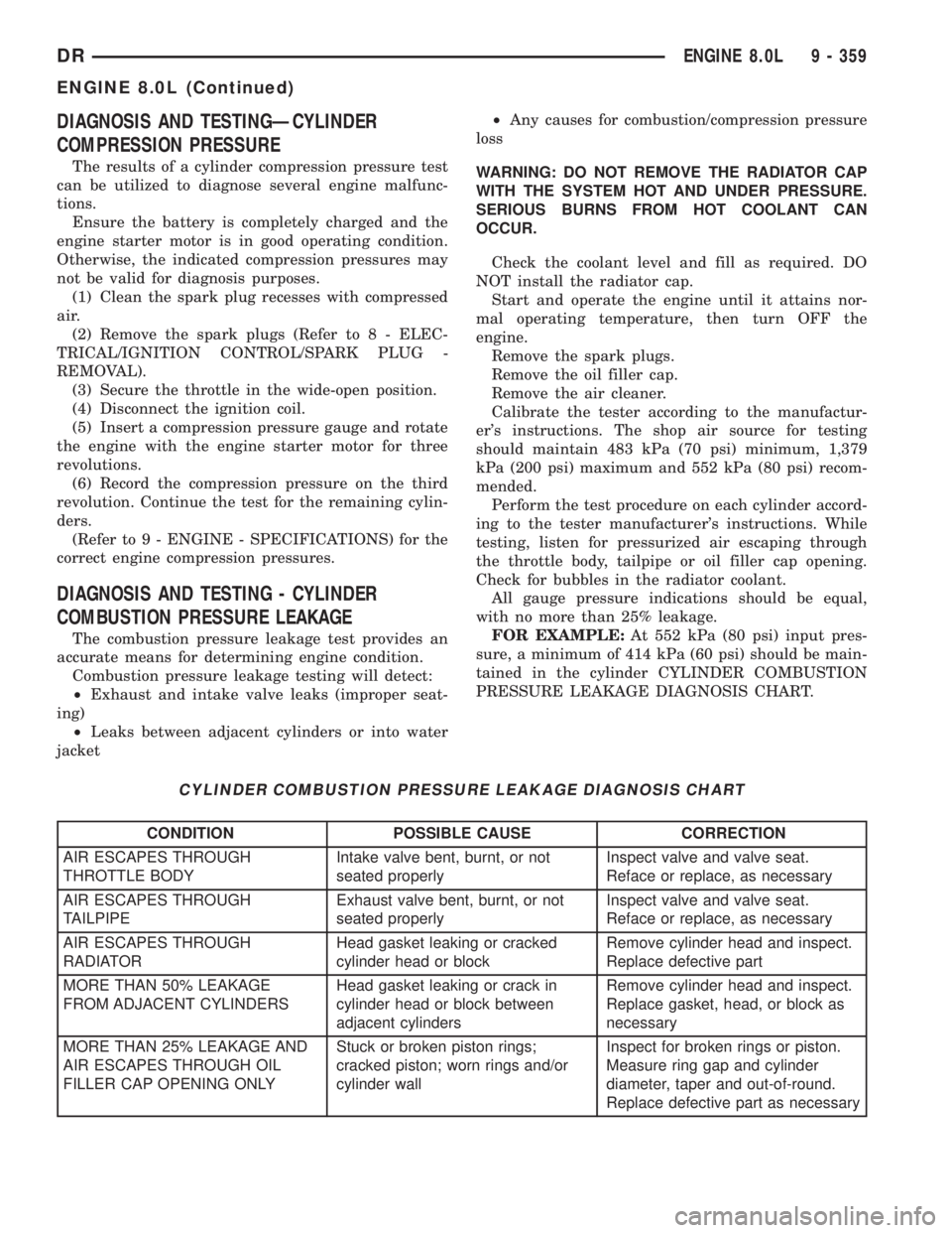
tained in the cylinder CYLINDER COMBUSTION
PRESSURE LEAKAGE DIAGNOSIS CHART.
CYLINDER COMBUSTION PRESSURE LEAKAGE DIAGNOSIS CHART
CONDITION POSSIBLE CAUSE CORRECTION
AIR ESCAPES THROUGH
THROTTLE BODYIntake valve bent, burnt, or not
seated properlyInspect valve and valve seat.
Reface or replace, as necessary
AIR ESCAPES THROUGH
TAILPIPEExhaust valve bent, burnt, or not
seated properlyInspect valve and valve seat.
Reface or replace, as necessary
AIR ESCAPES THROUGH
RADIATORHead gasket leaking or cracked
cylinder head or blockRemove cylinder head and inspect.
Replace defective part
MORE THAN 50% LEAKAGE
FROM ADJACENT CYLINDERSHead gasket leaking or crack in
cylinder head or block between
adjacent cylindersRemove cylinder head and inspect.
Replace gasket, head, or block as
necessary
MORE THAN 25% LEAKAGE AND
AIR ESCAPES THROUGH OIL
FILLER CAP OPENING ONLYStuck or broken piston rings;
cracked piston; worn rings and/or
cylinder wallInspect for broken rings or piston.
Measure ring gap and cylinder
diameter, taper and out-of-round.
Replace defective part as necessary
DRENGINE 8.0L 9 - 359
ENGINE 8.0L (Continued)
Page 1612 of 2895
(21) Install the generator and wire connections
(Refer to 8 - ELECTRICAL/CHARGING/GENERA-
TOR - INSTALLATION).
(22) Install the upper crossmember.
(23) Install radiator (Refer to 7 - COOLING/EN-
GINE/RADIATOR - INSTALLATION).
(24) Connect the lower radiator hose.
(25) Install the transmission oil cooler (Refer to 7 -
COOLING/TRANSMISSION/TRANS COOLER -
INSTALLATION).
(26) Connect the transmission cooler lines.
(27) Connect the power steering hoses, if equipped.
(28) Install the fan shroud.
(29) Install the fan (Refer to 7 - COOLING/EN-
GINE/RADIATOR FAN - INSTALLATION).
(30) Connect the top radiator hose.
(31) Install the washer fluid reservoir bottle (Refer
to 8 - ELECTRICAL/WIPERS/WASHERS - INSTAL-
LATION).
(32) If equipped, install the condenser (Refer to 24
- HEATING & AIR CONDITIONING/PLUMBING/
A/C CONDENSER - INSTALLATION).
(33) Install the A/C compressor with the lines
attached (Refer to 24 - HEATING & AIR CONDI-
TIONING/PLUMBING/A/C COMPRESSOR -
INSTALLATION).
(34) Install the serpentine belt (Refer to 7 - COOL-
ING/ACCESSORY DRIVE/DRIVE BELTS - INSTAL-
LATION).
(35) Evacuate (Refer to 24 - HEATING & AIR
CONDITIONING/PLUMBING - STANDARD PRO-
CEDURE) and charge the air conditioning system, if
equipped (Refer to 24 - HEATING & AIR CONDI-
TIONING/PLUMBING - STANDARD PROCEDURE).
(36) Add coolant to the cooling system (Refer to 7 -
COOLING - STANDARD PROCEDURE).
(37) Install the battery.
(38) Warm engine and adjust as required.
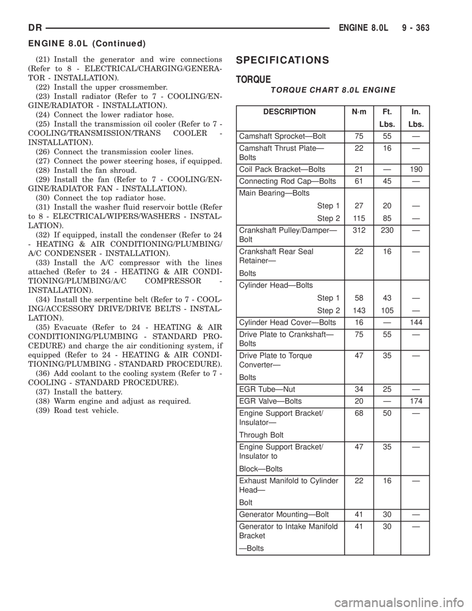
(39) Road test vehicle.SPECIFICATIONS
TORQUE
TORQUE CHART 8.0L ENGINE
DESCRIPTION N´m Ft. In.
Lbs. Lbs.
Camshaft SprocketÐBolt 75 55 Ð
Camshaft Thrust PlateÐ
Bolts22 16 Ð
Coil Pack BracketÐBolts 21 Ð 190
Connecting Rod CapÐBolts 61 45 Ð
Main BearingÐBolts
Step 1 27 20 Ð
Step 2 115 85 Ð
Crankshaft Pulley/DamperÐ
Bolt312 230 Ð
Crankshaft Rear Seal
RetainerÐ22 16 Ð
Bolts
Cylinder HeadÐBolts
Step 1 58 43 Ð
Step 2 143 105 Ð
Cylinder Head CoverÐBolts 16 Ð 144
Drive Plate to CrankshaftÐ
Bolts75 55 Ð
Drive Plate to Torque
ConverterÐ47 35 Ð
Bolts
EGR TubeÐNut 34 25 Ð
EGR ValveÐBolts 20 Ð 174
Engine Support Bracket/
InsulatorÐ68 50 Ð
Through Bolt
Engine Support Bracket/
Insulator to47 35 Ð
BlockÐBolts
Exhaust Manifold to Cylinder
HeadÐ22 16 Ð
Bolt
Generator MountingÐBolt 41 30 Ð
Generator to Intake Manifold
Bracket41 30 Ð
ÐBolts
DRENGINE 8.0L 9 - 363
ENGINE 8.0L (Continued)
Page 1633 of 2895
(1) Start bearing in place, and insert Crankshaft
Main Bearing Remover/Installer Tool C-3059 into oil
hole of crankshaft (Fig. 30).
(2) Slowly rotate crankshaft counterclockwise slid-
ing the bearing into position. Remove Tool C-3059.
(3) Lubricate the main journals with clean engine
oil. Install main bearing caps and bolts. Follow the 2
step tightening sequence, starting with No. 1 main
bearing cap.
(4) Apply a rearward axial load of 667 N (150
lbs-f) on crankshaft centerline, driving No.3 main cap
and thrust bearing against No.3 bulkhead. Repeat
procedure, driving crankshaft forward to align rear
flange of thrust bearings in a common plane. Front
face of No.1 main cap must not extend forward in
front of face of No.1 bulkhead.
(5) Install the oil pump pick-up tube and oil pan
(Refer to 9 - ENGINE/LUBRICATION/OIL PAN -
INSTALLATION).
CRANKSHAFT OIL SEAL -
FRONT
REMOVAL
REMOVALÐFRONT OIL SEAL - FRONT COVER
INSTALLED
(1) Disconnect the negative cable from the battery.
(2) Remove vibration damper from the crankshaft
(Refer to 9 - ENGINE/ENGINE BLOCK/VIBRATION
DAMPER - REMOVAL).(3) Place a suitable tool behind the lips of the oil
seal to pry the oil seal outward. Be careful not to
damage the crankshaft seal surface of the cover (Fig.
31).
REMOVALÐFRONT OIL SEAL - FRONT COVER
REMOVED
(1) Remove engine front cover (Refer to 9 -
ENGINE/VALVE TIMING/TIMING BELT / CHAIN
COVER(S) - REMOVAL).
(2) Place a suitable tool behind the lips of the oil
seal to pry the oil seal outward. Be careful not to
damage the crankshaft seal surface of the cover.
INSTALLATION
INSTALLATIONÐFRONT OIL SEAL ± FRONT
COVER INSTALLED
(1) Position the crankshaft front oil seal onto seal
installer special tool 6806 and C-3688 (Fig. 32).
Install seal.
(2) Install vibration damper (Refer to 9 - ENGINE/
ENGINE BLOCK/VIBRATION DAMPER - INSTAL-
LATION).
(3) Install serpentine belt (Refer to 7 - COOLING/
ACCESSORY DRIVE/DRIVE BELTS - INSTALLA-
TION).
(4) Install cooling fan and shroud (Refer to 7 -
COOLING/ENGINE/RADIATOR FAN - INSTALLA-
TION).
(5) Connect negative cable to the battery.
(6) Start engine and check for leaks.
INSTALLATIONÐFRONT OIL SEAL - FRONT
COVER REMOVED
(1) Position the crankshaft front oil seal onto seal
installer special tool 6806.
Fig. 30 Upper Main Bearing Removal and
Installation with Tool C-3059
1 - SPECIAL TOOL C-3059
2 - BEARING
3 - SPECIAL TOOL C-3059
4 - BEARINGFig. 31 Timing Chain Cover and Oil Seal
1 - TIMING CHAIN COVER
2 - OIL SEAL
9 - 384 ENGINE 8.0LDR
CRANKSHAFT MAIN BEARINGS (Continued)
Page 1835 of 2895
FLUID
DESCRIPTION
The recommended fluid for the power steering sys-
tem is MopartATF +4.
MopartATF+4, when new is red in color. The
ATF+4 is dyed red so it can be identified from other
fluids used in the vehicle such as engine oil or anti-
freeze. The red color is not permanent and is not an
indicator of fluid condition, As the vehicle is driven,
the ATF+4 will begin to look darker in color and may
eventually become brown.THIS IS NORMAL.
ATF+4 also has a unique odor that may change with
age. Consequently, odor and color cannot be used to
indicate the fluid condition or the need for a fluid
change.
STANDARD PROCEDURE - POWER STEERING
FLUID LEVEL CHECKING
WARNING: FLUID LEVEL SHOULD BE CHECKED
WITH THE ENGINE OFF TO PREVENT PERSONAL
INJURY FROM MOVING PARTS.
CAUTION: MOPARTATF+4 is to be used in the
power steering system. No other power steering or
automatic transmission fluid is to be used in the
system. Damage may result to the power steering
pump and system if any other fluid is used, and do
not overfill.
The power steering fluid level can be viewed on the
dipstick attached to the filler cap. There are two
ranges listed on the dipstick, COLD and HOT. Before
opening power steering system, wipe the reservoir
filler cap free of dirt and debris. Remove the cap and
check the fluid level on its dipstick. When the fluid is
at normal ambient temperature, approximately 21ÉC
to 27ÉC (70ÉF to 80ÉF), the fluid level should read
between the minimum and maximum area of the cold
range. When the fluid is hot, fluid level is allowed to
read up to the highest end of the HOT range. Only
add fluid when the vehicle is cold.
Use only MopartATF+4Do not overfill the
power steering system.
FLUID COOLER
REMOVAL
(1) Drain and siphon the power steering fluid.
(2) Disconnect the return and supply hoses con-
nected to the power steering fluid cooler.(3) Remove the mounting bracket bolts securing
the fluid cooler to the brace. (Fig. 4)& (Fig. 5)
(4) Remove the fluid cooler from the vehicle.
INSTALLATION
(1) Install the fluid cooler to the vehicle.
(2) Install the mounting bracket bolts securing the
fluid cooler to the brace (Fig. 4)& (Fig. 5).
(3) Reclamp the return and supply hoses to the
power steering fluid cooler.
(4) Refill the power steering fluid (Refer to 19 -
STEERING/PUMP - STANDARD PROCEDURE).
Fig. 4 V6 & V8 P/S FLUID COOLER
1 - POWER STEERING FLUID COOLER
2 - MOUNTING BOLTS
Fig. 5 V10 & DIESEL P/S FLUID COOLER
1 - RADIATOR
2 - POWER STEERING HOSES
3 - MOUNTING BOLTS
4 - P/S FLUID COOLER
19 - 42 PUMPDR
Page 2040 of 2895
FLUID AND FILTER
DIAGNOSIS AND TESTING
DIAGNOSIS AND TESTING - EFFECTS OF
INCORRECT FLUID LEVEL
A low fluid level allows the pump to take in air
along with the fluid. Air in the fluid will cause fluid
pressures to be low and develop slower than normal.
If the transmission is overfilled, the gears churn the
fluid into foam. This aerates the fluid and causing
the same conditions occurring with a low level. In
either case, air bubbles cause fluid overheating, oxi-
dation and varnish buildup which interferes with
valve and clutch operation. Foaming also causes fluid
expansion which can result in fluid overflow from the
transmission vent or fill tube. Fluid overflow can eas-
ily be mistaken for a leak if inspection is not careful.
DIAGNOSIS AND TESTING - CAUSES OF
BURNT FLUID
Burnt, discolored fluid is a result of overheating
which has two primary causes.
(1) A result of restricted fluid flow through the
main and/or auxiliary cooler. This condition is usu-
ally the result of a faulty or improperly installed
drainback valve, a damaged main cooler, or severe
restrictions in the coolers and lines caused by debris
or kinked lines.
(2) Heavy duty operation with a vehicle not prop-
erly equipped for this type of operation. Trailer tow-
ing or similar high load operation will overheat the
transmission fluid if the vehicle is improperly
equipped. Such vehicles should have an auxiliary
transmission fluid cooler, a heavy duty cooling sys-
tem, and the engine/axle ratio combination needed to
handle heavy loads.
DIAGNOSIS AND TESTING - FLUID
CONTAMINATION
Transmission fluid contamination is generally a
result of:
²adding incorrect fluid
²failure to clean dipstick and fill tube when
checking level
²engine coolant entering the fluid
²internal failure that generates debris
²overheat that generates sludge (fluid break-
down)
²failure to replace contaminated converter after
repair
The use of non-recommended fluids can result in
transmission failure. The usual results are erratic
shifts, slippage, abnormal wear and eventual failuredue to fluid breakdown and sludge formation. Avoid
this condition by using recommended fluids only.
The dipstick cap and fill tube should be wiped
clean before checking fluid level. Dirt, grease and
other foreign material on the cap and tube could fall
into the tube if not removed beforehand. Take the
time to wipe the cap and tube clean before withdraw-
ing the dipstick.
Engine coolant in the transmission fluid is gener-
ally caused by a cooler malfunction. The only remedy
is to replace the radiator as the cooler in the radiator
is not a serviceable part. If coolant has circulated
through the transmission, an overhaul is necessary.
The torque converter should be replaced whenever
a failure generates sludge and debris. This is neces-
sary because normal converter flushing procedures
will not remove all contaminants.
STANDARD PROCEDURE
STANDARD PROCEDURE - FLUID LEVEL
CHECK
Low fluid level can cause a variety of conditions
because it allows the pump to take in air along with
the fluid. As in any hydraulic system, air bubbles
make the fluid spongy, therefore, pressures will be
low and build up slowly.
Improper filling can also raise the fluid level too
high. When the transmssion has too much fluid, the
geartrain churns up foam and cause the same condi-
tions which occur with a low fluid level.
In either case, air bubbles can cause overheating
and/or fluid oxidation, and varnishing. This can
interfere with normal valve, clutch, and accumulator
operation. Foaming can also result in fluid escaping
from the transmission vent where it may be mis-
taken for a leak.
After the fluid has been checked, seat the dipstick
fully to seal out water and dirt.
The transmission has a dipstick to check oil level.
It is located on the right side of the engine. Be sure
to wipe all dirt from dipstick handle before removing.
Fluid level is checked with the engine running at
curb idle speed, the transmission in NEUTRAL and
the transmission fluid at normal operating tempera-
ture.The engine should be running at idle
speed for at least one minute, with the vehicle
on level ground.
The transmission fluid level can be checked two
ways.
PROCEDURE ONE
(1) Transmission fluid must be at normal operat-
ing temperature for accurate fluid level check. Drive
DRAUTOMATIC TRANSMISSION - 46RE 21 - 201
Page 2220 of 2895
FLUID AND FILTER
DIAGNOSIS AND TESTING
DIAGNOSIS AND TESTING - EFFECTS OF
INCORRECT FLUID LEVEL
A low fluid level allows the pump to take in air
along with the fluid. Air in the fluid will cause fluid
pressures to be low and develop slower than normal.
If the transmission is overfilled, the gears churn the
fluid into foam. This aerates the fluid and causing
the same conditions occurring with a low level. In
either case, air bubbles cause fluid overheating, oxi-
dation and varnish buildup which interferes with
valve and clutch operation. Foaming also causes fluid
expansion which can result in fluid overflow from the
transmission vent or fill tube. Fluid overflow can eas-
ily be mistaken for a leak if inspection is not careful.
DIAGNOSIS AND TESTING - CAUSES OF
BURNT FLUID
Burnt, discolored fluid is a result of overheating
which has two primary causes.
(1) A result of restricted fluid flow through the
main and/or auxiliary cooler. This condition is usu-
ally the result of a faulty or improperly installed
drainback valve, a damaged main cooler, or severe
restrictions in the coolers and lines caused by debris
or kinked lines.
(2) Heavy duty operation with a vehicle not prop-
erly equipped for this type of operation. Trailer tow-
ing or similar high load operation will overheat the
transmission fluid if the vehicle is improperly
equipped. Such vehicles should have an auxiliary
transmission fluid cooler, a heavy duty cooling sys-
tem, and the engine/axle ratio combination needed to
handle heavy loads.
DIAGNOSIS AND TESTING - FLUID
CONTAMINATION
Transmission fluid contamination is generally a
result of:
²adding incorrect fluid
²failure to clean dipstick and fill tube when
checking level
²engine coolant entering the fluid
²internal failure that generates debris
²overheat that generates sludge (fluid break-
down)
²failure to replace contaminated converter after
repair
The use of non-recommended fluids can result in
transmission failure. The usual results are erratic
shifts, slippage, abnormal wear and eventual failuredue to fluid breakdown and sludge formation. Avoid
this condition by using recommended fluids only.
The dipstick cap and fill tube should be wiped
clean before checking fluid level. Dirt, grease and
other foreign material on the cap and tube could fall
into the tube if not removed beforehand. Take the
time to wipe the cap and tube clean before withdraw-
ing the dipstick.
Engine coolant in the transmission fluid is gener-
ally caused by a cooler malfunction. The only remedy
is to replace the radiator as the cooler in the radiator
is not a serviceable part. If coolant has circulated
through the transmission, an overhaul is necessary.
The torque converter should be replaced whenever
a failure generates sludge and debris. This is neces-
sary because normal converter flushing procedures
will not remove all contaminants.
STANDARD PROCEDURE
STANDARD PROCEDURE - FLUID LEVEL
CHECK
Low fluid level can cause a variety of conditions
because it allows the pump to take in air along with
the fluid. As in any hydraulic system, air bubbles
make the fluid spongy, therefore, pressures will be
low and build up slowly.
Improper filling can also raise the fluid level too
high. When the transmssion has too much fluid, the
geartrain churns up foam and cause the same condi-
tions which occur with a low fluid level.
In either case, air bubbles can cause overheating
and/or fluid oxidation, and varnishing. This can
interfere with normal valve, clutch, and accumulator
operation. Foaming can also result in fluid escaping
from the transmission vent where it may be mis-
taken for a leak.
After the fluid has been checked, seat the dipstick
fully to seal out water and dirt.
The transmission has a dipstick to check oil level.
It is located on the right side of the engine. Be sure
to wipe all dirt from dipstick handle before removing.
Fluid level is checked with the engine running at
curb idle speed, the transmission in NEUTRAL and
the transmission fluid at normal operating tempera-
ture.The engine should be running at idle
speed for at least one minute, with the vehicle
on level ground.
The transmission fluid level can be checked two
ways.
PROCEDURE ONE
(1) Transmission fluid must be at normal operat-
ing temperature for accurate fluid level check. Drive
DRAUTOMATIC TRANSMISSION - 48RE 21 - 381