2003 DODGE RAM relay
[x] Cancel search: relayPage 503 of 2895

²Driver Door Lock Switch MUX - with
Power Locks
²Fused B(+) - Ignition-Off Draw
²Fused B(+) - Power Lock Feed - with Power
Locks
²Fused Ignition Switch Output (Accessory-
Run)
²Fused Ignition Switch Output (Off-Run-
Start)
²Fused Ignition Switch Output (Run-Start)
²Headlamp Dimmer Switch MUX
²Headlamp Switch MUX
²Horn Relay Control
²Key-In Ignition Switch Sense
²Left Rear Door Ajar Switch Sense
²Panel Lamps Dimmer Switch Signal
²Park Brake Switch Sense
²Passenger Door Ajar Switch Sense
²Passenger Door Lock Switch MUX - with
Power Locks
²Radio Control MUX
²Right Rear Door Ajar Switch Sense
²RKE Supply - with RKE
²Seat Belt Switch Sense
²Transmission Range Sensor MUX - with
Auto Trans
²Turn/Hazard Switch MUX
²Washer/Beam Select Switch MUX
²Wiper Switch MUX
Refer to the appropriate wiring information for
additional details.
HARD WIRED OUTPUTS
The hard wired outputs of the EMIC include the
following:
²Accessory Switch Bank Illumination Driver
²BTSI Driver - with Auto Trans
²Cargo Lamp Driver
²Dome/Overhead Lamp Driver
²Driver Door Unlock Driver - with Power
Locks
²Headlamp Switch Illumination Driver
²Heated Seat Switch Indicator Driver - with
Heated Seats
²Heater-A/C Control Illumination Driver
²Left Door Lock Driver - with Power Locks
²Left Rear Door Unlock Driver - with Power
Locks
²Map/Glove Box Lamp Driver²Radio Illumination Driver
²Right Door Lock Driver - with Power Locks
²Right Door Unlock Driver - with Power
Locks
²Transfer Case Switch Illumination Driver -
with Four-Wheel Drive
Refer to the appropriate wiring information for
additional details.
GROUNDS
The EMIC receives and supplies a ground path to
several switches and sensors through the following
hard wired circuits:
²Ground - Illumination (2 Circuits)
²Ground - Power Lock - with Power Locks
²Ground - Signal
²Headlamp Switch Return
²Multi-Function Switch Return
²Transmission Range Sensor Return - with
Auto Trans
Refer to the appropriate wiring information for
additional details.
COMMUNICATION
The EMIC has provisions for the following commu-
nication circuits:
²PCI Data Bus
²RKE Program Serial Data - with RKE
²RKE Transmit Serial Data - with RKE
Refer to the appropriate wiring information for
additional details.
DIAGNOSIS AND TESTING - INSTRUMENT
CLUSTER
If all of the instrument cluster gauges and/or indi-
cators are inoperative, refer to PRELIMINARY
DIAGNOSIS. If an individual gauge or Programma-
ble Communications Interface (PCI) data bus mes-
sage-controlled indicator is inoperative, refer to
ACTUATOR TEST. If an individual hard wired indi-
cator is inoperative, refer to the diagnosis and testing
information for that specific indicator.
Refer to the appropriate wiring information. The
wiring information includes wiring diagrams, proper
wire and connector repair procedures, details of wire
harness routing and retention, connector pin-out
information and location views for the various wire
harness connectors, splices and grounds.
8J - 10 INSTRUMENT CLUSTERDR
INSTRUMENT CLUSTER (Continued)
Page 532 of 2895
data bus, or the electronic message inputs to the
instrument cluster that control the transmission
over-temperature indicator, a DRBIIItscan tool is
required. Refer to the appropriate diagnostic infor-
mation.
TURN SIGNAL INDICATOR
DESCRIPTION
Two turn signal indicators, one right and one left,
are standard equipment on all instrument clusters.
The turn signal indicators are located near the upper
edge of the instrument cluster, between the speedom-
eter and the tachometer. Each turn signal indicator
consists of a stencil-like cutout of the International
Control and Display Symbol icon for ªTurn Warningº
in the opaque layer of the instrument cluster overlay.
The dark outer layer of the overlay prevents these
icons from being clearly visible when they are not
illuminated. A green Light Emitting Diode (LED)
behind each turn signal indicator cutout in the
opaque layer of the overlay causes the icon to appear
in green through the translucent outer layer of the
overlay when the indicator is illuminated from
behind by the LED, which is soldered onto the
instrument cluster electronic circuit board. The turn
signal indicators are serviced as a unit with the
instrument cluster.
OPERATION
The turn signal indicators give an indication to the
vehicle operator that the turn signal (left or right
indicator flashing) or hazard warning (both left and
right indicators flashing) have been selected and are
operating. These indicators are controlled by transis-
tors on the instrument cluster electronic circuit board
based upon the cluster programming, a hard wired
multiplex input received by the cluster from the turn
signal and hazard warning switch circuitry of the
multi-function switch on the turn/hazard switch mux
circuit, and electronic messages received from the
Front Control Module (FCM) over the Programmable
Communications Interface (PCI) data bus. Each turn
signal indicator Light Emitting Diode (LED) is com-
pletely controlled by the instrument cluster logic cir-
cuit, and that logic will allow this indicator to
operate whenever the instrument cluster receives a
battery current input on the fused B(+) circuit.
Therefore, each LED can be illuminated regardless of
the ignition switch position. The LED only illumi-
nates when it is provided a path to ground by the
instrument cluster transistor. The instrument cluster
will turn on the turn signal indicators for the follow-
ing reasons:²Turn Signal-On Input- Each time the cluster
detects a turn signal-on input from the turn signal
switch circuitry of the multi-function switch on the
turn/hazard switch mux circuit, the requested turn
signal lamps and turn signal indicator will be flashed
on and off, and an electromechanical relay soldered
onto the cluster electronic circuit board will produce
a clicking sound to emulate a conventional turn sig-
nal flasher. The turn signals and the turn signal
indicators continue to flash on and off until the clus-
ter receives a turn signal-off input from the multi-
function switch, or until the ignition switch is turned
to the Off position, whichever occurs first. The
instrument cluster also sends an electronic message
to the FCM over the PCI data bus, and the FCM
flashes the appropriate exterior turn signal lamps. If
the FCM detects an inoperative turn signal circuit, it
increases the flash rate for the remaining operative
turn signals and sends an electronic message to the
instrument cluster. The instrument cluster then
increases the flash rate of the turn signal indicator
and the clicking rate of the electromechanical relay
to provide an indication of the problem to the vehicle
operator.
²Hazard Warning-On Input- Each time the
cluster detects a hazard warning-on input from the
hazard warning switch circuitry of the multi-function
switch on the turn/hazard switch mux circuit, all of
the turn signal lamps and both turn signal indicators
will be flashed on and off, and an electromechanical
relay soldered onto the cluster electronic circuit
board will produce a clicking sound to emulate a con-
ventional hazard warning flasher. The turn signals
and the turn signal indicators continue to flash on
and off until the cluster receives a hazard warning-
off input from the multi-function switch. The instru-
ment cluster also sends an electronic message to the
FCM over the PCI data bus, and the FCM flashes all
of the exterior turn signal lamps. If the FCM detects
an inoperative turn signal circuit, it increases the
flash rate for the remaining operative turn signals
and sends an electronic message to the instrument
cluster. The instrument cluster then increases the
flash rate of both turn signal indicators and the click-
ing rate of the electromechanical relay to provide an
indication of the problem to the vehicle operator.
²Actuator Test- Each time the cluster is put
through the actuator test, the turn signal indicators
will be turned on, then off again during the bulb
check portion of the test to confirm the functionality
of each LED and the cluster control circuitry.
The instrument cluster continually monitors the
multi-function switch to determine the proper turn
signal and hazard warning system control. The
instrument cluster then sends the proper turn signal
and hazard warning flasher-on and flasher-off mes-
DRINSTRUMENT CLUSTER 8J - 39
TRANS TEMP INDICATOR (Continued)
Page 538 of 2895
LAMPS
TABLE OF CONTENTS
page page
LAMPS/LIGHTING - EXTERIOR............... 1LAMPS/LIGHTING - INTERIOR............... 24
LAMPS/LIGHTING - EXTERIOR
TABLE OF CONTENTS
page page
LAMPS/LIGHTING - EXTERIOR
DESCRIPTION..........................2
OPERATION............................2
DIAGNOSIS AND TESTING - LAMPS/
LIGHTING - EXTERIOR..................3
STANDARD PROCEDURE
SAFETY PRECAUTIONS.................7
SPECIFICATIONS
EXTERIOR LAMPS.....................7
SPECIAL TOOLS - HEADLAMP ALIGNMENT . . . 7
BACKUP LAMP
REMOVAL.............................7
INSTALLATION..........................7
BACKUP LAMP SWITCH
DESCRIPTION..........................7
OPERATION............................8
DIAGNOSIS AND TESTING - BACKUP LAMP
SWITCH.............................8
BRAKE LAMP
REMOVAL.............................8
INSTALLATION..........................8
BRAKE LAMP SWITCH
DESCRIPTION..........................8
OPERATION............................8
DIAGNOSIS AND TESTING - BRAKE LAMP
SWITCH.............................9
REMOVAL.............................9
INSTALLATION.........................10
CENTER HIGH MOUNTED STOP LAMP
REMOVAL.............................10
INSTALLATION.........................10
CENTER HIGH MOUNTED STOP LAMP UNIT
REMOVAL.............................10
INSTALLATION.........................10
CAB CLEARANCE LAMP
REMOVAL.............................10
INSTALLATION.........................10FOG LAMP
REMOVAL.............................11
INSTALLATION.........................11
FOG LAMP RELAY
DESCRIPTION.........................11
OPERATION...........................12
DIAGNOSIS AND TESTING - FRONT FOG
LAMP RELAY.........................12
REMOVAL.............................13
INSTALLATION.........................13
HAZARD SWITCH
DESCRIPTION.........................13
OPERATION...........................13
HEADLAMP
REMOVAL.............................13
INSTALLATION.........................13
HEADLAMP SWITCH
DESCRIPTION.........................14
OPERATION...........................14
REMOVAL.............................14
INSTALLATION.........................14
HEADLAMP UNIT
REMOVAL.............................15
INSTALLATION.........................15
ADJUSTMENTS........................15
LICENSE PLATE LAMP
REMOVAL.............................16
INSTALLATION.........................16
LICENSE PLATE LAMP UNIT
REMOVAL.............................16
INSTALLATION.........................16
MARKER LAMP UNIT
REMOVAL
REMOVAL...........................16
REMOVAL...........................16
INSTALLATION
INSTALLATION.......................17
INSTALLATION.......................17
DRLAMPS 8L - 1
Page 539 of 2895
MULTI-FUNCTION SWITCH
DESCRIPTION - TURN SIGNAL SYSTEM.....17
OPERATION - TURN SIGNAL SYSTEM.......18
DIAGNOSIS AND TESTING - MULTI-
FUNCTION SWITCH...................18
REMOVAL.............................18
INSTALLATION.........................19
PARK LAMP RELAY
DESCRIPTION.........................19
OPERATION...........................19
DIAGNOSIS AND TESTING - PARK LAMP
RELAY..............................20
REMOVAL.............................20
INSTALLATION.........................21
PARK/TURN SIGNAL LAMP
REMOVAL.............................21
INSTALLATION.........................21TAIL LAMP
REMOVAL.............................21
INSTALLATION.........................21
TAIL LAMP UNIT
REMOVAL.............................21
INSTALLATION.........................21
TRAILER TOW WIRING
DESCRIPTION.........................22
TURN LAMP
REMOVAL.............................22
INSTALLATION.........................22
UNDERHOOD LAMP
REMOVAL.............................22
INSTALLATION.........................22
UNDERHOOD LAMP UNIT
REMOVAL.............................22
INSTALLATION.........................23
LAMPS/LIGHTING - EXTERIOR
DESCRIPTION
The exterior lighting system for this model include
the following components:
²Backup Lamps
²Brake Lamps
²Daytime Running Lamps
²Front Fog Lamps
²Hazard Warning Lamps
²Headlamps
²Park Lamps
²Turn Signal Lamps
Other components of the exterior lighting system
for this model include:
²Backup Lamp Switch
²Brake Lamp Switch
²Front Control Module
²Front Fog Lamp Relay
²Hazard Switch
²Multi-Function Switch
²Park Lamp Relay
²Trailer Tow Connectors
Some of the interior and exterior lighting functions
are governed by the front control module. The head-
lamp, dome, and door ajar switchs provide signals to
the instrument cluster. The instrument cluster sends
a J1850 message to the front control module to
enable the necessary components for illumination.
Hard wired circuitry connects the exterior lighting
system components to the electrical system of the
vehicle. Refer to the appropriate wiring information.
OPERATION
DAYTIME RUNNING LAMPS
Power is reduced using pulse-width modulation to
the high beams, where by the power is switched on
and off rapidly instead of remaining on continuously.
The duration and interval of the power pulses is pro-
grammed into the Front Control Module (FCM).
HEADLAMP SYSTEM
The instrument cluster monitors both the multi-
plexed headlamp and multifunction switches. The
instrument cluster transmits a J1850 bus message to
the front control module (FCM) to activate the head-
lamps. The headlamp system will default to head-
lamps ON position when ignition switch is ON and
when an open or short circuit failure occurs on the
headlamp switch input to the instrument cluster. The
system will return to normal operation when the
open or short is repaired. A fault will be reported by
the Instrument Cluster when a failure occurs on the
dimmer or headlamp switch input.
If the exterior lamps are ON, and the headlamp
switch is in any position other than OFF, with the
ignition switch OFF (LOCK) after 5 minutes, the
Instrument Cluster transmits a message via J1850
informing the the FCM. The FCM will then turn off
the headlamps, park lamps and fog lamps. This fea-
ture (load shed) prevents the vehicle battery from
being discharged when the vehicle lights have been
left ON.
HEADLAMP TIME DELAY SYSTEM
The headlamp time delay system is activated by
turning the headlamps ON (high or low beam) while
the engine is running, turning the ignition switch
OFF, and then turning the headlamp switch OFF
8L - 2 LAMPS/LIGHTING - EXTERIORDR
Page 540 of 2895
within 45 seconds. The system will not activate if
more than 45 seconds elapse between ignition switch
OFF and headlamp switch OFF. The FCM will allow
the headlamps to remain ON for 60 seconds (config-
urable) before they automatically turn off (If the key
is in the ignition during the headlamp time delay
mode, then the headlamps including panel dimming
will be ON).
LAMP OUTAGE
If one or more of the following lamps (Low and/or
High beams, Brake and/or Turn Signal) are out, then
a ªlamps outº indicator located in the cluster will
illuminate.
OPTICAL HORN/HIGH BEAMS
When the multiplexed multifunction switch is
pulled to the first detent (optical horn) signal, the
headlamps are ON, the Instrument Cluster shall
send a message via J1850 to the FCM to turn on the
headlamps drivers to illuminate all four filaments
(Low and High beams). When the multifunction
switch is pulled to the second detent (high beam) sig-
nal and the headlamps are ON, the Instrument Clus-
ter shall send a message via J1850 to the FCM to
turn on the headlamps drivers. The High Beams are
illuminated and the Low Beams and Fog Lamps (if
ON) are extinguished. If the headlamps were in the
high beam configuration when power was removed
from the headlamps, the headlamps will return to
their last state prior to being shut off.
DIAGNOSIS AND TESTING - LAMPS/LIGHTING
- EXTERIOR
WARNING: EYE PROTECTION SHOULD BE USED
WHEN SERVICING GLASS COMPONENTS. PER-
SONAL INJURY CAN RESULT.
CAUTION: Do not touch the glass of halogen bulbs
with fingers or other possibly oily surface, reduced
bulb life will result. Do not use bulbs other than
those indicated in the Bulb Application table. Dam-
age to lamp and/or Daytime Running Lamp Module
can result. Do not use fuses, circuit breakers or
relays having greater amperage value than indi-
cated on the fuse panel or in the Owners Manual.
When a vehicle experiences problems with the
headlamp system, verify the condition of the battery
connections, fuses, charging system, headlamp bulbs,
wire connectors, relay, multifunction switch, and
headlamp switch. Refer to the appropriate wiring
information.
Each vehicle is equipped with various lamp assem-
blies. A good ground is necessary for proper lighting
operation. Grounding is provided by the lamp socket
when it comes in contact with the metal body, or
through a separate ground wire.
When changing lamp bulbs check the socket for
loose pin connections and corrosion. Repair as neces-
sary.
When it is necessary to remove components to ser-
vice another, it should not be necessary to apply
excessive force or bend a component to remove it.
Before damaging a trim component, verify hidden
fasteners or captured edges are not holding the com-
ponent in place.
DRLAMPS/LIGHTING - EXTERIOR 8L - 3
LAMPS/LIGHTING - EXTERIOR (Continued)
Page 543 of 2895
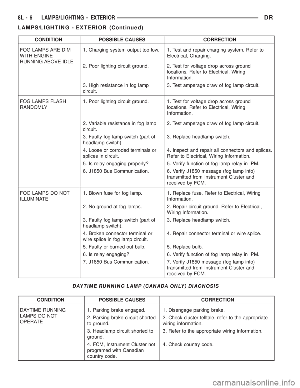
CONDITION POSSIBLE CAUSES CORRECTION
FOG LAMPS ARE DIM
WITH ENGINE
RUNNING ABOVE IDLE1. Charging system output too low. 1. Test and repair charging system. Refer to
Electrical, Charging.
2. Poor lighting circuit ground. 2. Test for voltage drop across ground
locations. Refer to Electrical, Wiring
Information.
3. High resistance in fog lamp
circuit.3. Test amperage draw of fog lamp circuit.
FOG LAMPS FLASH
RANDOMLY1. Poor lighting circuit ground. 1. Test for voltage drop across ground
locations. Refer to Electrical, Wiring
Information.
2. Variable resistance in fog lamp
circuit.2. Test amperage draw of fog lamp circuit.
3. Faulty fog lamp switch (part of
headlamp switch).3. Replace headlamp switch.
4. Loose or corroded terminals or
splices in circuit.4. Inspect and repair all connectors and splices.
Refer to Electrical, Wiring Information.
5. Is relay engaging properly? 5. Verify function of fog lamp relay in IPM.
6. J1850 Bus Communication. 6. Verify J1850 message (fog lamp info)
transmitted from Instrument Cluster and
received by FCM.
FOG LAMPS DO NOT
ILLUMINATE1. Blown fuse for fog lamp. 1. Replace fuse. Refer to Electrical, Wiring
Information.
2. No ground at fog lamps. 2. Repair circuit ground. Refer to Electrical,
Wiring Information.
3. Faulty fog lamp switch (part of
headlamp switch).3. Replace headlamp switch.
4. Broken connector terminal or
wire splice in fog lamp circuit.4. Repair connector terminal or wire splice.
5. Faulty or burned out bulb. 5. Replace bulb.
6. Is relay engaging? 6. Verify function of fog lamp relay in IPM.
7. J1850 Bus Communication. 7. Verify J1850 message (fog lamp info)
transmitted from Instrument Cluster and
received by FCM.
DAYTIME RUNNING LAMP (CANADA ONLY) DIAGNOSIS
CONDITION POSSIBLE CAUSES CORRECTION
DAYTIME RUNNING
LAMPS DO NOT
OPERATE1. Parking brake engaged. 1. Disengage parking brake.
2. Parking brake circuit shorted
to ground.2. Check cluster telltale, refer to the appropriate
wiring information.
3. Headlamp circuit shorted to
ground.3. Refer to the appropriate wiring information.
4. FCM, Instrument Cluster not
programed with Canadian
country code.4. Check country code.
8L - 6 LAMPS/LIGHTING - EXTERIORDR
LAMPS/LIGHTING - EXTERIOR (Continued)
Page 544 of 2895

STANDARD PROCEDURE
SAFETY PRECAUTIONS
WARNING: EYE PROTECTION SHOULD BE USED
WHEN SERVICING GLASS COMPONENTS. PER-
SONAL INJURY CAN RESULT.
CAUTION: Do not touch the glass of halogen bulbs
with fingers or other possibly oily surface, reduced
bulb life will result.Do not use bulbs with higher
candle power than indicated in the Bulb Application
table . Damage to lamp and/or Daytime Running
Lamp Module can result.Do not use fuses, circuit
breakers or relays having greater amperage value
than indicated on the fuse panel or in the Owners
Manual.
When it is necessary to remove components to ser-
vice another, it should not be necessary to apply
excessive force or bend a component to remove it.
Before damaging a trim component, verify hidden
fasteners or captured edges are not holding the com-
ponent in place.
SPECIFICATIONS
EXTERIOR LAMPS
CAUTION: Do not use bulbs that have a higher can-
dle power than the bulb listed in the Bulb Applica-
tion Table. Damage to lamp can result. Do not touch
halogen bulbs with fingers or other oily surfaces.
Bulb life will be reduced.
The following Bulb Application Table lists the lamp
title on the left side of the column and trade number
or part number on the right.
BULB APPLICATION TABLE
LAMP BULB
Back-up 3157
Center High Mounted
Stop lamp912
Fog lamp 9006LL
Front Park/Turn Signal 4157NAK
Head lamp 9007
License Plate 7F69
Tail, Brake, Turn Signal 3157
Side Marker, Tail Gate,
Cab Clearance168
SPECIAL TOOLS - HEADLAMP ALIGNMENT
BACKUP LAMP
REMOVAL
(1) Remove and isolate the negitive battery cable.
(2) Remove the taillamp unit (Refer to 8 - ELEC-
TRICAL/LAMPS/LIGHTING - EXTERIOR/TAIL
LAMP UNIT - REMOVAL).
(3) Remove the bulb back plate from the tail lamp
unit.
(4) Separate the bulb from the socket.
INSTALLATION
(1) Install the bulb into the socket.
(2) Install the bulb back plate to the tail lamp
unit.
(3) Install the tail lamp unit (Refer to 8 - ELEC-
TRICAL/LAMPS/LIGHTING - EXTERIOR/TAIL
LAMP UNIT - INSTALLATION).
(4) Reconnect the negative battery cable.
BACKUP LAMP SWITCH
DESCRIPTION
Vehicles equipped with a manual transmission
have a normally open, spring-loaded plunger type
back-up lamp switch (Fig. 1). The backup lamp
switch is located in a threaded hole on the side of the
manual transmission housing. The backup lamp
switch has a threaded body and a hex formation near
the plunger end of the switch, and an integral con-
nector at the opposite end of the switch. When
installed, only the connector and the hex formation
are visible on the outside of the transmission hous-
ing. Vehicles with an optional electronic automatic
transmission have a Transmission Range Sensor
(TRS) that is used to perform several functions,
including that of the backup lamp switch. The TRS is
described in further detail elsewhere in this service
information. The backup lamp switch cannot be
adjusted or repaired and, if faulty or damaged, the
entire switch unit must be replaced.
Headlamp Aiming Kit C-4466±A
DRLAMPS/LIGHTING - EXTERIOR 8L - 7
LAMPS/LIGHTING - EXTERIOR (Continued)
Page 548 of 2895
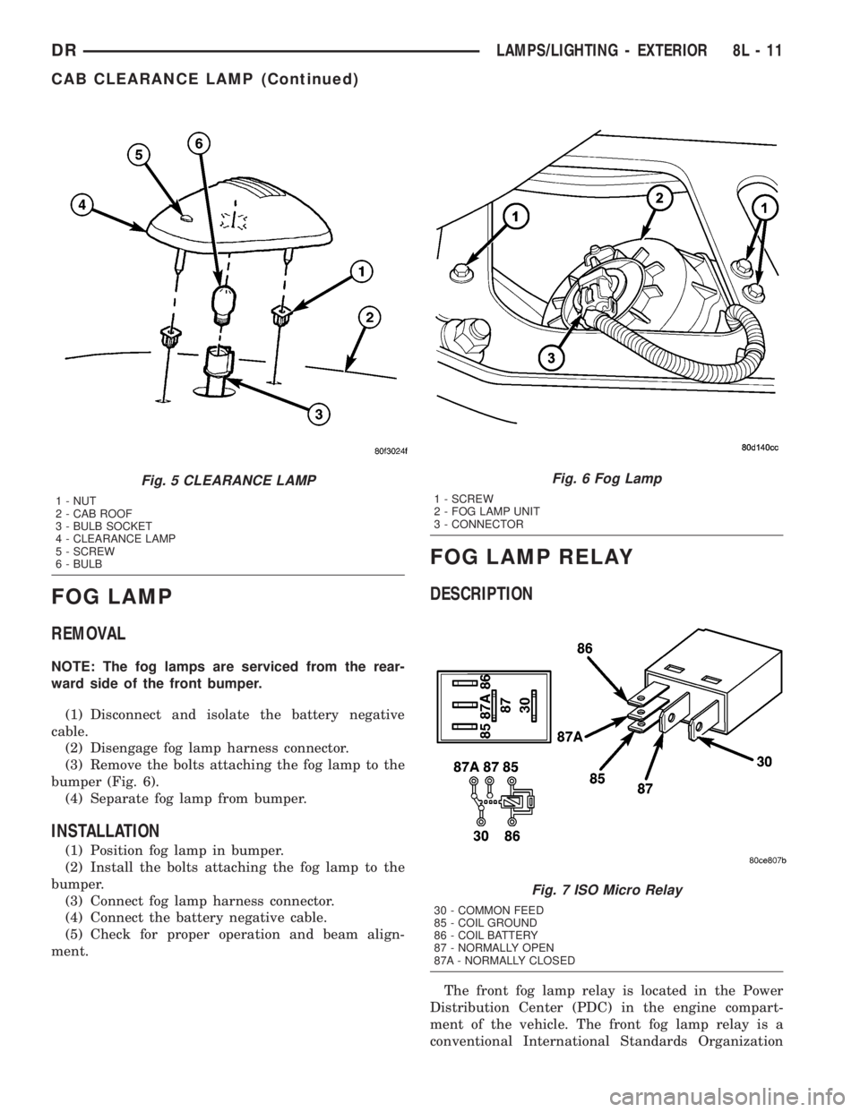
FOG LAMP
REMOVAL
NOTE: The fog lamps are serviced from the rear-
ward side of the front bumper.
(1) Disconnect and isolate the battery negative
cable.
(2) Disengage fog lamp harness connector.
(3) Remove the bolts attaching the fog lamp to the
bumper (Fig. 6).
(4) Separate fog lamp from bumper.
INSTALLATION
(1) Position fog lamp in bumper.
(2) Install the bolts attaching the fog lamp to the
bumper.
(3) Connect fog lamp harness connector.
(4) Connect the battery negative cable.
(5) Check for proper operation and beam align-
ment.
FOG LAMP RELAY
DESCRIPTION
The front fog lamp relay is located in the Power
Distribution Center (PDC) in the engine compart-
ment of the vehicle. The front fog lamp relay is a
conventional International Standards Organization
Fig. 5 CLEARANCE LAMP
1 - NUT
2 - CAB ROOF
3 - BULB SOCKET
4 - CLEARANCE LAMP
5 - SCREW
6 - BULB
Fig. 6 Fog Lamp
1 - SCREW
2 - FOG LAMP UNIT
3 - CONNECTOR
Fig. 7 ISO Micro Relay
30 - COMMON FEED
85 - COIL GROUND
86 - COIL BATTERY
87 - NORMALLY OPEN
87A - NORMALLY CLOSED
DRLAMPS/LIGHTING - EXTERIOR 8L - 11
CAB CLEARANCE LAMP (Continued)