Page 2345 of 2895

(27) Install the reaction planetary gear set and the
number 9 bearing, with the inner race against the
reaction planetary carrier, into the transmission case
(Fig. 41).
(28) Install the flat 2C clutch snap-ring into the
transmission case (Fig. 40).
(29) Install the reaction sun gear into the reaction
planetary gear set.Make surethe small shoulder is
facing the front of the transmission (Fig. 41).
(30) Install the number 7 bearing onto the reaction
sun gear with the inner race against the sun gear
(Fig. 41).
(31) Install the output shaft selective thrust plate
onto the reaction annulus with the oil grooves facing
the annulus gear and the tabs and notches aligned as
shown in (Fig. 42).
(32)
Install the number 6 bearing against the output
shaft selective thrust plate with the flat side against the
thrust plate (Fig. 41) and the raised tabs on the inner
race facing the front of the transmission.
(33) Install the reaction annulus into the reaction
planetary gear set (Fig. 41).
Fig. 41 Install Reaction Annulus and Carrier
1 - BEARING NUMBER 8 5 - BEARING NUMBER 7
2 - BEARING NUMBER 9 6 - THRUST PLATE (SELECT)
3 - REACTION PLANETARY CARRIER 7 - BEARING NUMBER 6
4 - REACTION SUN GEAR 8 - REACTION ANNULUS
Fig. 42 Thrust Plate Alignment
1 - LOCATING LUG (3)
2 - THRUST PLATE
21 - 506 AUTOMATIC TRANSMISSION - 45RFE/545RFEDR
AUTOMATIC TRANSMISSION - 45RFE/545RFE (Continued)
Page 2346 of 2895
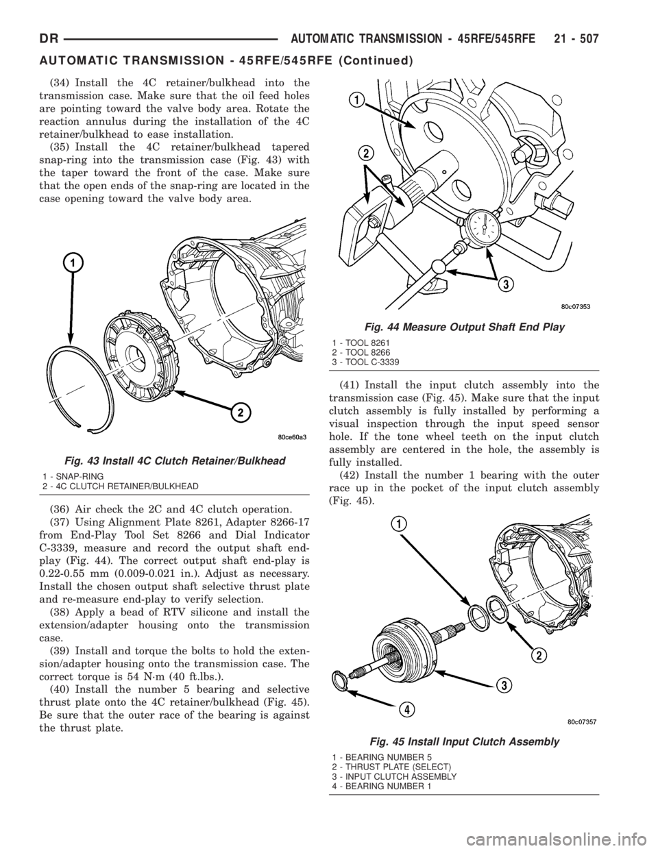
(34) Install the 4C retainer/bulkhead into the
transmission case. Make sure that the oil feed holes
are pointing toward the valve body area. Rotate the
reaction annulus during the installation of the 4C
retainer/bulkhead to ease installation.
(35) Install the 4C retainer/bulkhead tapered
snap-ring into the transmission case (Fig. 43) with
the taper toward the front of the case. Make sure
that the open ends of the snap-ring are located in the
case opening toward the valve body area.
(36) Air check the 2C and 4C clutch operation.
(37) Using Alignment Plate 8261, Adapter 8266-17
from End-Play Tool Set 8266 and Dial Indicator
C-3339, measure and record the output shaft end-
play (Fig. 44). The correct output shaft end-play is
0.22-0.55 mm (0.009-0.021 in.). Adjust as necessary.
Install the chosen output shaft selective thrust plate
and re-measure end-play to verify selection.
(38) Apply a bead of RTV silicone and install the
extension/adapter housing onto the transmission
case.
(39) Install and torque the bolts to hold the exten-
sion/adapter housing onto the transmission case. The
correct torque is 54 N´m (40 ft.lbs.).
(40) Install the number 5 bearing and selective
thrust plate onto the 4C retainer/bulkhead (Fig. 45).
Be sure that the outer race of the bearing is against
the thrust plate.(41) Install the input clutch assembly into the
transmission case (Fig. 45). Make sure that the input
clutch assembly is fully installed by performing a
visual inspection through the input speed sensor
hole. If the tone wheel teeth on the input clutch
assembly are centered in the hole, the assembly is
fully installed.
(42) Install the number 1 bearing with the outer
race up in the pocket of the input clutch assembly
(Fig. 45).
Fig. 43 Install 4C Clutch Retainer/Bulkhead
1 - SNAP-RING
2 - 4C CLUTCH RETAINER/BULKHEAD
Fig. 44 Measure Output Shaft End Play
1 - TOOL 8261
2 - TOOL 8266
3 - TOOL C-3339
Fig. 45 Install Input Clutch Assembly
1 - BEARING NUMBER 5
2 - THRUST PLATE (SELECT)
3 - INPUT CLUTCH ASSEMBLY
4 - BEARING NUMBER 1
DRAUTOMATIC TRANSMISSION - 45RFE/545RFE 21 - 507
AUTOMATIC TRANSMISSION - 45RFE/545RFE (Continued)
Page 2347 of 2895

(43) Install the oil pump into the transmission
case (Fig. 46).
(44) Install the bolts to hold the oil pump into the
transmission case. Tighten the oil pump bolts to 28
N´m (250 in.lbs.).
(45) Using Adapter 8266-1 from End-Play Tool Set
8266 and Dial Indicator C-3339, measure and record
the input shaft end-play (Fig. 47). The correct end-
play is 0.46-0.89 mm (0.018-0.035 in.). Adjust as nec-
essary. Install the chosen thrust plate on the number
5 bearing and re-measure end-play to verify selec-
tion.
NOTE: When measuring the input shaft end-play,
two(stops(will be felt. When the input shaft is
pushed inward and the dial indicator zeroed, the
first(stop(felt when the input shaft is pulled out-
ward is the movement of the input shaft in the input
clutch housing hub. This value should not be
included in the end-play measured value and there-
fore must be recorded and subtracted from the dial
indicator reading.
(46) Install the transmission front cover into the
transmission case (Fig. 48).
(47) Install the outer snap-ring to hold the trans-
mission front cover into the transmission case (Fig.
48).
(48) Partially install the inner transmission front
cover snap-ring onto the oil pump (Fig. 48).
Fig. 46 Install Oil Pump
1 - OIL PUMP TO CASE BOLT (6)
2 - OIL PUMP
Fig. 47 Measure Input Shaft End Play
1 - TOOL 8266
2 - TOOL C-3339
Fig. 48 Install the Transmission Front Cover
1 - INNER SNAP-RING
2 - TRANSMISSION COVER
3 - OUTER SNAP-RING
21 - 508 AUTOMATIC TRANSMISSION - 45RFE/545RFEDR
AUTOMATIC TRANSMISSION - 45RFE/545RFE (Continued)
Page 2350 of 2895
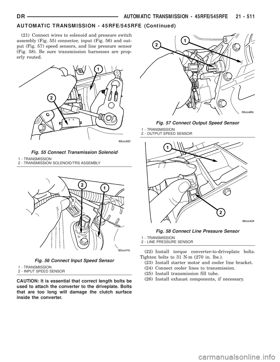
(21) Connect wires to solenoid and pressure switch
assembly (Fig. 55) connector, input (Fig. 56) and out-
put (Fig. 57) speed sensors, and line pressure sensor
(Fig. 58). Be sure transmission harnesses are prop-
erly routed.
CAUTION: It is essential that correct length bolts be
used to attach the converter to the driveplate. Bolts
that are too long will damage the clutch surface
inside the converter.(22) Install torque converter-to-driveplate bolts.
Tighten bolts to 31 N´m (270 in. lbs.).
(23) Install starter motor and cooler line bracket.
(24) Connect cooler lines to transmission.
(25) Install transmission fill tube.
(26) Install exhaust components, if necessary.
Fig. 55 Connect Transmission Solenoid
1 - TRANSMISSION
2 - TRANSMISSION SOLENOID/TRS ASSEMBLY
Fig. 56 Connect Input Speed Sensor
1 - TRANSMISSION
2 - INPUT SPEED SENSOR
Fig. 57 Connect Output Speed Sensor
1 - TRANSMISSION
2 - OUTPUT SPEED SENSOR
Fig. 58 Connect Line Pressure Sensor
1 - TRANSMISSION
2 - LINE PRESSURE SENSOR
DRAUTOMATIC TRANSMISSION - 45RFE/545RFE 21 - 511
AUTOMATIC TRANSMISSION - 45RFE/545RFE (Continued)
Page 2373 of 2895
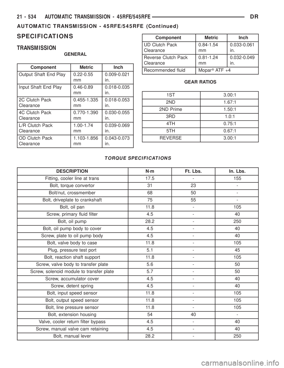
SPECIFICATIONS
TRANSMISSION
GENERAL
Component Metric Inch
Output Shaft End Play 0.22-0.55
mm0.009-0.021
in.
Input Shaft End Play 0.46-0.89
mm0.018-0.035
in.
2C Clutch Pack
Clearance0.455-1.335
mm0.018-0.053
in.
4C Clutch Pack
Clearance0.770-1.390
mm0.030-0.055
in.
L/R Clutch Pack
Clearance1.00-1.74
mm0.039-0.069
in.
OD Clutch Pack
Clearance1.103-1.856
mm0.043-0.073
in.
Component Metric Inch
UD Clutch Pack
Clearance0.84-1.54
mm0.033-0.061
in.
Reverse Clutch Pack
Clearance0.81-1.24
mm0.032-0.049
in.
Recommended fluid MoparTAT F + 4
GEAR RATIOS
1ST 3.00:1
2ND 1.67:1
2ND Prime 1.50:1
3RD 1.0:1
4TH 0.75:1
5TH 0.67:1
REVERSE 3.00:1
TORQUE SPECIFICATIONS
DESCRIPTION N´m Ft. Lbs. In. Lbs.
Fitting, cooler line at trans 17.5 - 155
Bolt, torque convertor 31 23 -
Bolt/nut, crossmember 68 50 -
Bolt, driveplate to crankshaft 75 55 -
Bolt, oil pan 11.8 - 105
Screw, primary fluid filter 4.5 - 40
Bolt, oil pump 28.2 - 250
Bolt, oil pump body to cover 4.5 - 40
Screw, plate to oil pump body 4.5 - 40
Bolt, valve body to case 11.8 - 105
Plug, pressure test port 5.1 - 45
Bolt, reaction shaft support 11.8 - 105
Screw, valve body to transfer plate 5.6 - 50
Screw, solenoid module to transfer plate 5.7 - 50
Screw, accumulator cover 4.5 - 40
Screw, detent spring 4.5 - 40
Bolt, input speed sensor 11.8 - 105
Bolt, output speed sensor 11.8 - 105
Bolt, line pressure sensor 11.8 - 105
Bolt, extension housing 54 40 -
Valve, cooler return filter bypass 4.5 - 40
Screw, manual valve cam retaining 4.5 - 40
Bolt, manual lever 28.2 - 250
21 - 534 AUTOMATIC TRANSMISSION - 45RFE/545RFEDR
AUTOMATIC TRANSMISSION - 45RFE/545RFE (Continued)
Page 2375 of 2895
Installer, Seal - 8253
Installer, Seal - 8254
Installer, Snap-ring - 8255
Stand, Support - 8257
Adapter, Pressure Tap - 8258-A
Adapter, Line Pressure - 8259
Fixture, Input Clutch Pressure - 8260
Plate, Alignment - 8261
21 - 536 AUTOMATIC TRANSMISSION - 45RFE/545RFEDR
AUTOMATIC TRANSMISSION - 45RFE/545RFE (Continued)
Page 2377 of 2895

4C RETAINER/BULKHEAD
DISASSEMBLY
(1) Remove the 2C piston belleville spring snap-
ring from the 4C retainer /bulkhead (Fig. 60).
(2) Remove the 2C piston Belleville spring from
the retainer/bulkhead (Fig. 60).
(3) Remove the 2C piston from the retainer/bulk-
head. Use 20 psi of air pressure to remove the piston
if necessary.
(4) Remove the 4C clutch snap-ring from the
retainer/bulkhead (Fig. 60).
(5) Remove the 4C clutch pack from the retainer/
bulkhead (Fig. 60).
(6) Using Spring Compressor 8250 and a suitable
shop press, compress the 4C piston return spring and
remove the snap-ring (Fig. 60).(7) Remove the 4C piston return spring and piston
from the retainer/bulkhead (Fig. 60). Use 20 psi of
air pressure to remove the piston if necessary.ASSEMBLY
(1) Clean and inspect all components. Replace any
components which show evidence of excessive wear
or scoring.
(2) Install new seals on the 2C and 4C pistons
(Fig. 60).
(3) Lubricate all seals with MopartATF +4 prior
to installation.
(4) Install the 4C piston into the 4C retainer/bulk-
head (Fig. 60).
(5) Position the 4C piston return spring onto the
4C piston.
Fig. 60 4C Retainer/Bulkhead Components
1 - SEAL 8 - REACTION PLATE
2 - 2C PISTON 9 - SNAP-RING
3 - PLATE 10 - RETURN SPRING
4 - DISC 11 - SEAL
5 - 2C BELLEVILLE SPRING 12 - 4C PISTON
6 - SNAP-RING 13 - 4C RETAINER/BULKHEAD
7 - SNAP-RING (SELECT)
21 - 538 AUTOMATIC TRANSMISSION - 45RFE/545RFEDR
Page 2378 of 2895

(6) Using Spring Compressor 8250 and a suitable
shop press, compress the 4C piston return spring and
install the snap-ring (Fig. 61).
(7) Assemble and install the 4C clutch pack into
the retainer/bulkhead (Fig. 60) with the steel separa-
tor plate against the piston.
(8) Install the 4C reaction plate and snap-ring into
the retainer/bulkhead (Fig. 60). The 4C reaction plate
is non-directional.
(9) Measure the 4C clutch clearance. The correct
clutch clearance is 0.77-1.39 mm (0.030-0.055 in.).
The snap-ring is selectable. Install the chosen snap-
ring and re-measure to verify the selection.
(10) Install the 2C piston into the retainer/bulk-
head (Fig. 60).
(11) Position the 2C Belleville spring onto the 2C
piston.
(12) Position the 2C Belleville spring snap-ring
onto the 2C Belleville spring (Fig. 60).
(13) Using Spring Compressor 8249 and a suitable
shop press (Fig. 62), compress the belleville spring
until the snap-ring is engaged with the snap-ring
groove in the retainer/bulkhead.
ADAPTER HOUSING SEAL
REMOVAL
(1) Remove the transfer case from the transmis-
sion.
(2) Using a screw mounted on a slide hammer,
remove the adapter housing seal.
INSTALLATION
(1) Clean the adapter seal bore in the adapter
housing of any residue or particles remaining from
the original seal.
(2) Install new oil seal in the adapter housing
using Seal Installer C-3860-A (Fig. 63). A properly
installed seal is flush to the face of the seal bore.
(3) Install the transfer case onto the transmission.
Fig. 61 Compress 4C Piston Return Spring Using
Tool 8250
1 - PRESS
2 - TOOL 8250
Fig. 62 Compress 2C Belleville Spring Using Tool
8249
1 - PRESS
2 - TOOL 8249
Fig. 63 Adapter Housing Seal Installation
1 - TOOL C-3860-A
DRAUTOMATIC TRANSMISSION - 45RFE/545RFE 21 - 539
4C RETAINER/BULKHEAD (Continued)
