2003 DODGE RAM wheel bolt torque
[x] Cancel search: wheel bolt torquePage 484 of 2895

NOTE: Over or under tightening the sensor mount-
ing bolts will affect knock sensor performance, pos-
sibly causing improper spark control. Always use
the specified torque when installing the knock sen-
sors. The torque for the knock senor bolt is rela-
tively light for an 8mm bolt.
NOTE: Note foam strip on bolt threads. This foam is
used only to retain the bolts to sensors for plant
assembly. It is not used as a sealant. Do not apply
any adhesive, sealant or thread locking compound
to these bolts.
(3) Install and tighten mounting bolts. Refer to
torque specification.
(4) Install intake manifold. Refer to Engine sec-
tion.
(5) Connect knock sensor wiring harness to engine
harness at rear of intake manifold.
5.7L V-8
(1) Thoroughly clean knock sensor mounting hole.
(2) Install sensor into cylinder block.
NOTE: Over or under tightening the sensor mount-
ing bolts will affect knock sensor performance, pos-
sibly causing improper spark control. Always use
the specified torque when installing the knock sen-
sors. The torque for the knock senor bolt is rela-
tively light for an 8mm bolt.
NOTE: Note foam strip on bolt threads. This foam is
used only to retain the bolts to sensors for plant
assembly. It is not used as a sealant. Do not apply
any adhesive, sealant or thread locking compound
to these bolts.
(3) Install and tighten mounting bolt. Refer to
torque specification.
(4) Install electrical connector to sensor.
SPARK PLUG
DESCRIPTION
Resistor type spark plugs are used on all engines.
Sixteen spark plugs (2 per cylinder) are used with
5.7L V-8 engines.
DIAGNOSIS AND TESTING - SPARK PLUG
CONDITIONS
To prevent possible pre-ignition and/or mechanical
engine damage, the correct type/heat range/number
spark plug must be used.
Always use the recommended torque when tighten-
ing spark plugs. Incorrect torque can distort the
spark plug and change plug gap. It can also pull the
plug threads and do possible damage to both the
spark plug and the cylinder head.
Remove the spark plugs and examine them for
burned electrodes and fouled, cracked or broken por-
celain insulators. Keep plugs arranged in the order
in which they were removed from the engine. A sin-
gle plug displaying an abnormal condition indicates
that a problem exists in the corresponding cylinder.
Replace spark plugs at the intervals recommended in
the Lubrication and Maintenance section.
Spark plugs that have low mileage may be cleaned
and reused if not otherwise defective, carbon or oil
fouled.
CAUTION: Never use a motorized wire wheel brush
to clean the spark plugs. Metallic deposits will
remain on the spark plug insulator and will cause
plug misfire.
Spark plug resistance values range from 6,000 to
20,000 ohms (when checked with at least a 1000 volt
spark plug tester).Do not use an ohmmeter to
check the resistance values of the spark plugs.
Inaccurate readings will result.
NORMAL OPERATING
The few deposits present on the spark plug will
probably be light tan or slightly gray in color. This is
evident with most grades of commercial gasoline
(Fig. 42). There will not be evidence of electrode
burning. Gap growth will not average more than
approximately 0.025 mm (.001 in) per 3200 km (2000
miles) of operation. Spark plugs that have normal
wear can usually be cleaned, have the electrodes
filed, have the gap set and then be installed.
Some fuel refiners in several areas of the United
States have introduced a manganese additive (MMT)
for unleaded fuel. During combustion, fuel with MMT
causes the entire tip of the spark plug to be coated
with a rust colored deposit. This rust color can be
misdiagnosed as being caused by coolant in the com-
bustion chamber. Spark plug performance may be
affected by MMT deposits.
DRIGNITION CONTROL 8I - 27
KNOCK SENSOR (Continued)
Page 1281 of 2895
(6) Air ingested into oil due to broken or cracked
oil pump pick up.
(7) Worn valve guides.
(8) Rocker arm ears contacting valve spring
retainer.
(9) Rocker arm loose, adjuster stuck or at maxi-
mum extension and still leaves lash in the system.
(10) Oil leak or excessive cam bore wear in cylin-
der head.
(11) Faulty lash adjuster.
a. Check lash adjusters for sponginess while
installed in cylinder head and cam on camshaft at
base circle. Depress part of rocker arm over adjuster.
Normal adjusters should feel very firm. Spongy
adjusters can be bottomed out easily.
b. Remove suspected lash adjusters, and replace.
c. Before installation, make sure adjusters are at
least partially full of oil. This can be verified by little
or no plunger travel when lash adjuster is depressed.
REMOVAL
(1) Disconnect battery negative cable.
(2) Raise the vehicle on a hoist.
(3) Disconnect the exhaust pipe at the right side
exhaust manifold.
(4) Drain the engine coolant(Refer to 7 - COOL-
ING - STANDARD PROCEDURE).
(5) Lower the vehicle.
(6) Remove the intake manifold(Refer to 9 -
ENGINE/MANIFOLDS/INTAKE MANIFOLD -
REMOVAL).
(7) Remove the cylinder head cover(Refer to 9 -
ENGINE/CYLINDER HEAD - REMOVAL).
(8) Remove the fan shroud(Refer to 7 - COOLING/
ENGINE/RADIATOR FAN - REMOVAL).
(9) Remove oil fill housing from cylinder head.
(10) Remove accessory drive belt(Refer to 7 -
COOLING/ACCESSORY DRIVE/DRIVE BELTS -
REMOVAL).
(11) Rotate the crankshaft until the damper timing
mark is aligned with TDC indicator mark.
(12) Verify the V6 mark on the camshaft sprocket
is at the 12 o'clock position. Rotate the crankshaft
one turn if necessary.
(13) Remove the crankshaft damper(Refer to 9 -
ENGINE/ENGINE BLOCK/VIBRATION DAMPER -
REMOVAL).
(14) Remove the timing chain cover(Refer to 9 -
ENGINE/VALVE TIMING/TIMING BELT / CHAIN
COVER(S) - REMOVAL).
(15) Lock the secondary timing chains to the idler
sprocket using Special Tool 8429 Timing Chain Hold-
ing Fixture.
NOTE: Mark the secondary timing chain prior to
removal to aid in installation.(16) Mark the secondary timing chain, one link on
each side of the V6 mark on the camshaft drive gear.
(17) Remove the right side secondary chain ten-
sioner(Refer to 9 - ENGINE/VALVE TIMING/TIM-
ING BELT/CHAIN AND SPROCKETS - REMOVAL).
(18) Remove the cylinder head access plug.
(19) Remove the right side secondary chain
guide(Refer to 9 - ENGINE/VALVE TIMING/TIMING
BELT/CHAIN AND SPROCKETS - REMOVAL).
CAUTION: The nut on the right side camshaft
sprocket should not be removed for any reason, as
the sprocket and camshaft sensor target wheel is
serviced as an assembly. If the nut was removed
retorque nut to 5 N´m (44 in. lbs.).
(20) Remove the retaining bolt and the camshaft
drive gear.
CAUTION: Do not allow the engine to rotate. severe
damage to the valve train can occur.
CAUTION: Do not overlook the four smaller bolts at
the front of the cylinder head. Do not attempt to
remove the cylinder head without removing these
four bolts.
CAUTION: Do not hold or pry on the camshaft tar-
get wheel for any reason. A damaged target wheel
can result in a vehicle no start condition.
NOTE: The cylinder head is attached to the cylinder
block with twelve bolts.
(21) Remove the cylinder head retaining bolts.
(22) Remove the cylinder head and gasket. Discard
the gasket.
CAUTION: Do not lay the cylinder head on its gas-
ket sealing surface, do to the design of the cylinder
head gasket any distortion to the cylinder head
sealing surface may prevent the gasket from prop-
erly sealing resulting in leaks.
INSTALLATION
NOTE: The cylinder head bolts are tightened using
a torque plus angle procedure. The bolts must be
examined BEFORE reuse. If the threads are necked
down the bolts should be replaced.
Necking can be checked by holding a straight edge
against the threads (Fig. 24). If all the threads do not
contact the scale, the bolt should be replaced.
9 - 32 ENGINE - 3.7LDR
CYLINDER HEAD - RIGHT (Continued)
Page 1282 of 2895
CAUTION: When cleaning cylinder head and cylin-
der block surfaces, DO NOT use a metal scraper
because the surfaces could be cut or ground. Use
only a wooden or plastic scraper.
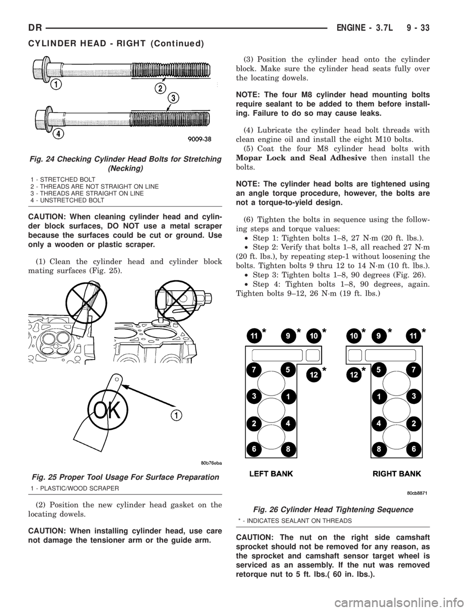
(1) Clean the cylinder head and cylinder block
mating surfaces (Fig. 25).
(2) Position the new cylinder head gasket on the
locating dowels.
CAUTION: When installing cylinder head, use care
not damage the tensioner arm or the guide arm.(3) Position the cylinder head onto the cylinder
block. Make sure the cylinder head seats fully over
the locating dowels.
NOTE: The four M8 cylinder head mounting bolts
require sealant to be added to them before install-
ing. Failure to do so may cause leaks.
(4) Lubricate the cylinder head bolt threads with
clean engine oil and install the eight M10 bolts.
(5) Coat the four M8 cylinder head bolts with
Mopar Lock and Seal Adhesivethen install the
bolts.
NOTE: The cylinder head bolts are tightened using
an angle torque procedure, however, the bolts are
not a torque-to-yield design.
(6) Tighten the bolts in sequence using the follow-
ing steps and torque values:
²Step 1: Tighten bolts 1±8, 27 N´m (20 ft. lbs.).
²Step 2: Verify that bolts 1±8, all reached 27 N´m
(20 ft. lbs.), by repeating step-1 without loosening the
bolts. Tighten bolts 9 thru 12 to 14 N´m (10 ft. lbs.).
²Step 3: Tighten bolts 1±8, 90 degrees (Fig. 26).
²Step 4: Tighten bolts 1±8, 90 degrees, again.
Tighten bolts 9±12, 26 N´m (19 ft. lbs.)
CAUTION: The nut on the right side camshaft
sprocket should not be removed for any reason, as
the sprocket and camshaft sensor target wheel is
serviced as an assembly. If the nut was removed
retorque nut to 5 ft. lbs.( 60 in. lbs.).
Fig. 24 Checking Cylinder Head Bolts for Stretching
(Necking)
1 - STRETCHED BOLT
2 - THREADS ARE NOT STRAIGHT ON LINE
3 - THREADS ARE STRAIGHT ON LINE
4 - UNSTRETCHED BOLT
Fig. 25 Proper Tool Usage For Surface Preparation
1 - PLASTIC/WOOD SCRAPER
Fig. 26 Cylinder Head Tightening Sequence
* - INDICATES SEALANT ON THREADS
DRENGINE - 3.7L 9 - 33
CYLINDER HEAD - RIGHT (Continued)
Page 1290 of 2895
INSTALLATION
CAUTION: Main bearings are select fit. Refer to
Crankshaft Main Bearings in this section for proper
bearing selections.
CAUTION: When installing crankshaft, use care not
to damage bearing surfaces on the crankshaft.
NOTE: Apply sealant to the tone wheel retaining
screws prior to installation.
(1) Lubricate upper main bearing halves with
clean engine oil.
(2) Install the crankshaft tone wheel. Torque the
mounting screws to 15 N´m (11 ft. lbs.).
(3) Position crankshaft in cylinder block.
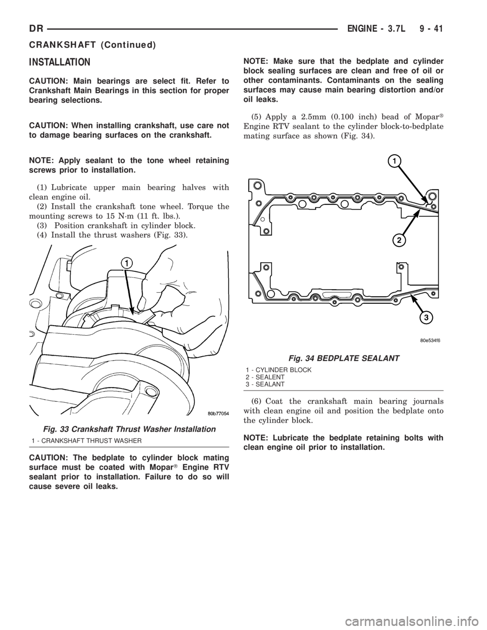
(4) Install the thrust washers (Fig. 33).
CAUTION: The bedplate to cylinder block mating
surface must be coated with MoparTEngine RTV
sealant prior to installation. Failure to do so will
cause severe oil leaks.NOTE: Make sure that the bedplate and cylinder
block sealing surfaces are clean and free of oil or
other contaminants. Contaminants on the sealing
surfaces may cause main bearing distortion and/or
oil leaks.
(5) Apply a 2.5mm (0.100 inch) bead of Mopart
Engine RTV sealant to the cylinder block-to-bedplate
mating surface as shown (Fig. 34).
(6) Coat the crankshaft main bearing journals
with clean engine oil and position the bedplate onto
the cylinder block.
NOTE: Lubricate the bedplate retaining bolts with
clean engine oil prior to installation.
Fig. 33 Crankshaft Thrust Washer Installation
1 - CRANKSHAFT THRUST WASHER
Fig. 34 BEDPLATE SEALANT
1 - CYLINDER BLOCK
2 - SEALENT
3 - SEALANT
DRENGINE - 3.7L 9 - 41
CRANKSHAFT (Continued)
Page 1366 of 2895
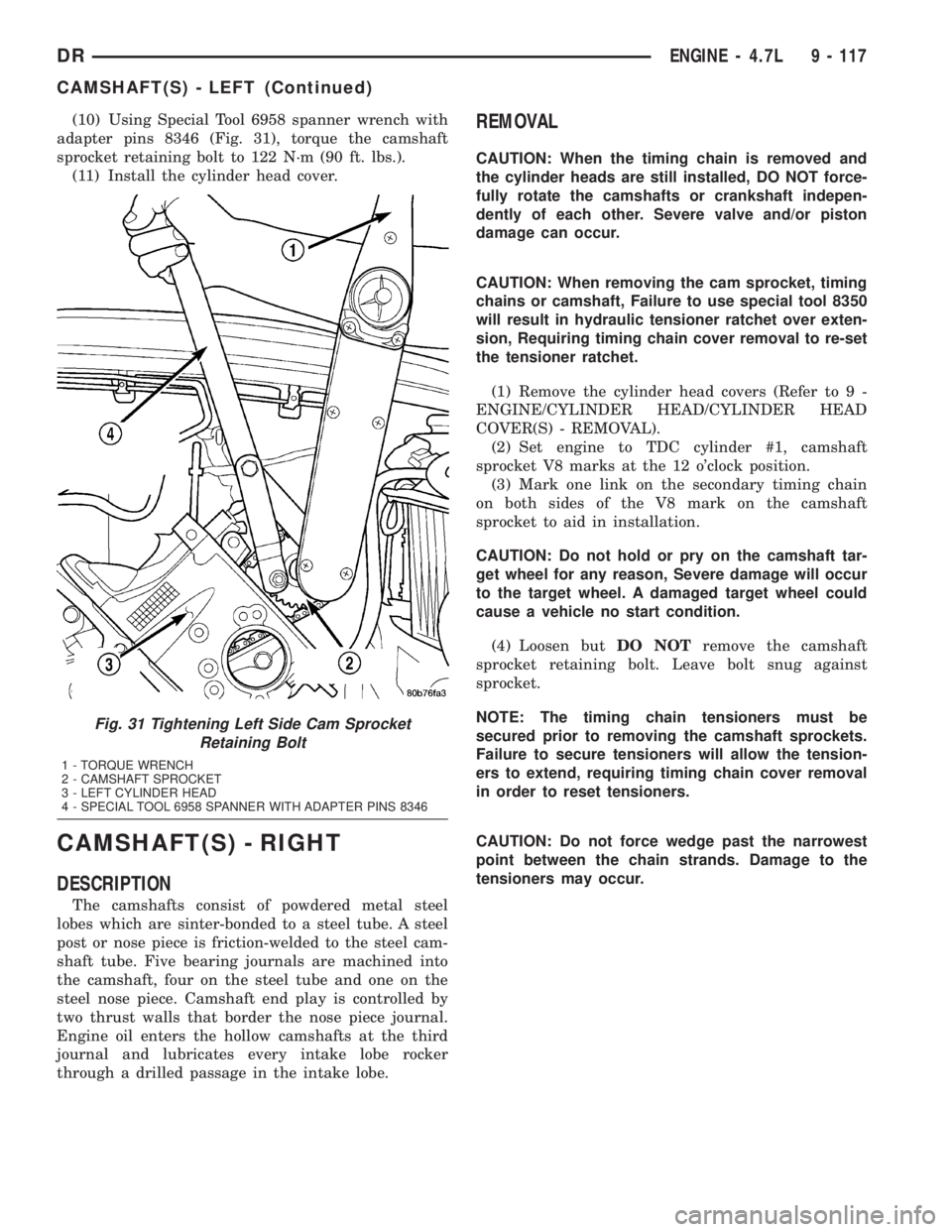
(10) Using Special Tool 6958 spanner wrench with
adapter pins 8346 (Fig. 31), torque the camshaft
sprocket retaining bolt to 122 N´m (90 ft. lbs.).
(11) Install the cylinder head cover.
CAMSHAFT(S) - RIGHT
DESCRIPTION
The camshafts consist of powdered metal steel
lobes which are sinter-bonded to a steel tube. A steel
post or nose piece is friction-welded to the steel cam-
shaft tube. Five bearing journals are machined into
the camshaft, four on the steel tube and one on the
steel nose piece. Camshaft end play is controlled by
two thrust walls that border the nose piece journal.
Engine oil enters the hollow camshafts at the third
journal and lubricates every intake lobe rocker
through a drilled passage in the intake lobe.
REMOVAL
CAUTION: When the timing chain is removed and
the cylinder heads are still installed, DO NOT force-
fully rotate the camshafts or crankshaft indepen-
dently of each other. Severe valve and/or piston
damage can occur.
CAUTION: When removing the cam sprocket, timing
chains or camshaft, Failure to use special tool 8350
will result in hydraulic tensioner ratchet over exten-
sion, Requiring timing chain cover removal to re-set
the tensioner ratchet.
(1) Remove the cylinder head covers (Refer to 9 -
ENGINE/CYLINDER HEAD/CYLINDER HEAD
COVER(S) - REMOVAL).
(2) Set engine to TDC cylinder #1, camshaft
sprocket V8 marks at the 12 o'clock position.
(3) Mark one link on the secondary timing chain
on both sides of the V8 mark on the camshaft
sprocket to aid in installation.
CAUTION: Do not hold or pry on the camshaft tar-
get wheel for any reason, Severe damage will occur
to the target wheel. A damaged target wheel could
cause a vehicle no start condition.
(4) Loosen butDO NOTremove the camshaft
sprocket retaining bolt. Leave bolt snug against
sprocket.
NOTE: The timing chain tensioners must be
secured prior to removing the camshaft sprockets.
Failure to secure tensioners will allow the tension-
ers to extend, requiring timing chain cover removal
in order to reset tensioners.
CAUTION: Do not force wedge past the narrowest
point between the chain strands. Damage to the
tensioners may occur.
Fig. 31 Tightening Left Side Cam Sprocket
Retaining Bolt
1 - TORQUE WRENCH
2 - CAMSHAFT SPROCKET
3 - LEFT CYLINDER HEAD
4 - SPECIAL TOOL 6958 SPANNER WITH ADAPTER PINS 8346
DRENGINE - 4.7L 9 - 117
CAMSHAFT(S) - LEFT (Continued)
Page 1434 of 2895
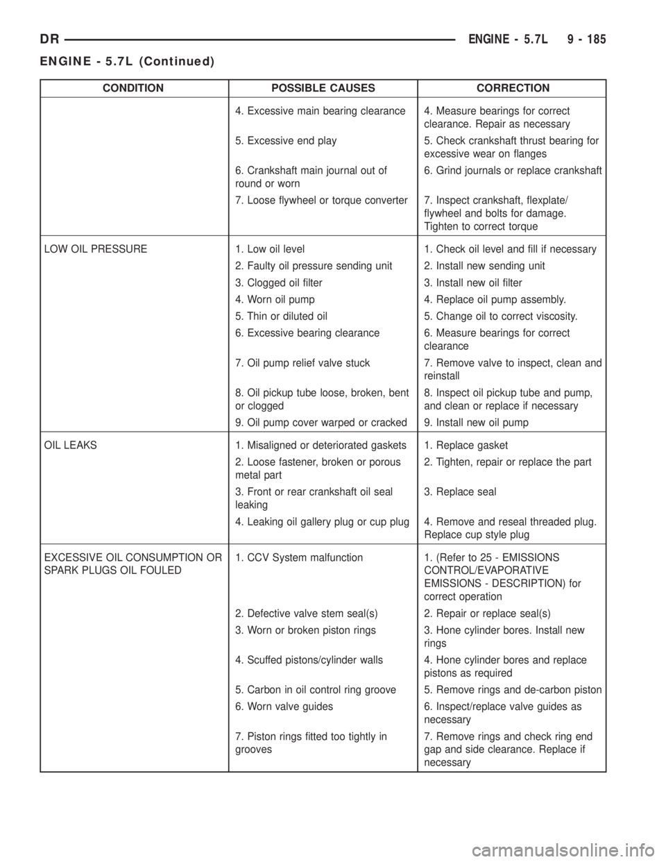
CONDITION POSSIBLE CAUSES CORRECTION
4. Excessive main bearing clearance 4. Measure bearings for correct
clearance. Repair as necessary
5. Excessive end play 5. Check crankshaft thrust bearing for
excessive wear on flanges
6. Crankshaft main journal out of
round or worn6. Grind journals or replace crankshaft
7. Loose flywheel or torque converter 7. Inspect crankshaft, flexplate/
flywheel and bolts for damage.
Tighten to correct torque
LOW OIL PRESSURE 1. Low oil level 1. Check oil level and fill if necessary
2. Faulty oil pressure sending unit 2. Install new sending unit
3. Clogged oil filter 3. Install new oil filter
4. Worn oil pump 4. Replace oil pump assembly.
5. Thin or diluted oil 5. Change oil to correct viscosity.
6. Excessive bearing clearance 6. Measure bearings for correct
clearance
7. Oil pump relief valve stuck 7. Remove valve to inspect, clean and
reinstall
8. Oil pickup tube loose, broken, bent
or clogged8. Inspect oil pickup tube and pump,
and clean or replace if necessary
9. Oil pump cover warped or cracked 9. Install new oil pump
OIL LEAKS 1. Misaligned or deteriorated gaskets 1. Replace gasket
2. Loose fastener, broken or porous
metal part2. Tighten, repair or replace the part
3. Front or rear crankshaft oil seal
leaking3. Replace seal
4. Leaking oil gallery plug or cup plug 4. Remove and reseal threaded plug.
Replace cup style plug
EXCESSIVE OIL CONSUMPTION OR
SPARK PLUGS OIL FOULED1. CCV System malfunction 1. (Refer to 25 - EMISSIONS
CONTROL/EVAPORATIVE
EMISSIONS - DESCRIPTION) for
correct operation
2. Defective valve stem seal(s) 2. Repair or replace seal(s)
3. Worn or broken piston rings 3. Hone cylinder bores. Install new
rings
4. Scuffed pistons/cylinder walls 4. Hone cylinder bores and replace
pistons as required
5. Carbon in oil control ring groove 5. Remove rings and de-carbon piston
6. Worn valve guides 6. Inspect/replace valve guides as
necessary
7. Piston rings fitted too tightly in
grooves7. Remove rings and check ring end
gap and side clearance. Replace if
necessary
DRENGINE - 5.7L 9 - 185
ENGINE - 5.7L (Continued)
Page 1440 of 2895
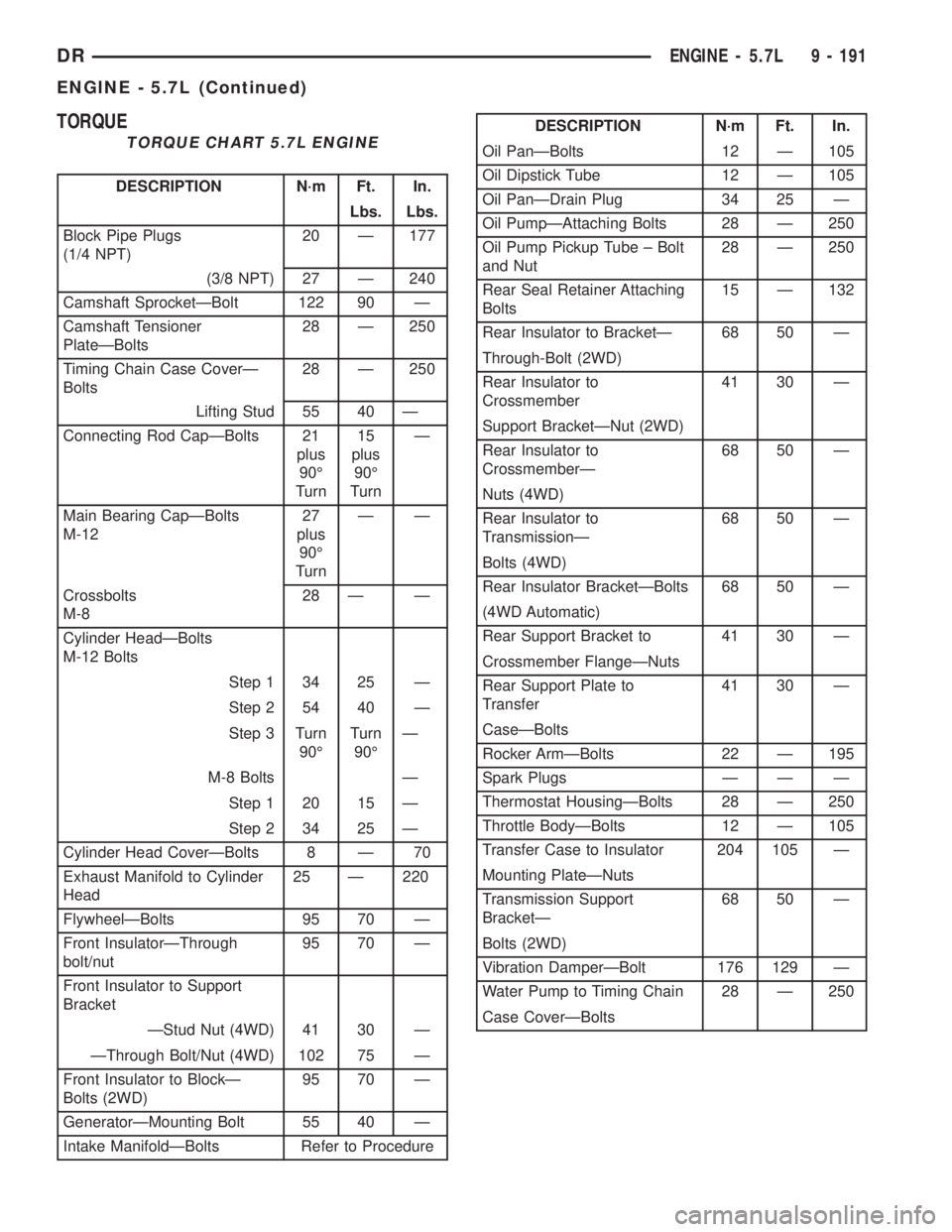
TORQUE
TORQUE CHART 5.7L ENGINE
DESCRIPTION N´m Ft. In.
Lbs. Lbs.
Block Pipe Plugs
(1/4 NPT)20 Ð 177
(3/8 NPT) 27 Ð 240
Camshaft SprocketÐBolt 122 90 Ð
Camshaft Tensioner
PlateÐBolts28 Ð 250
Timing Chain Case CoverÐ
Bolts28 Ð 250
Lifting Stud 55 40 Ð
Connecting Rod CapÐBolts 21
plus
90É
Turn15
plus
90É
TurnÐ
Main Bearing CapÐBolts
M-1227
plus
90É
TurnÐÐ
Crossbolts
M-828 Ð Ð
Cylinder HeadÐBolts
M-12 Bolts
Step 1 34 25 Ð
Step 2 54 40 Ð
Step 3 Turn
90ÉTurn
90ÉÐ
M-8 Bolts Ð
Step 1 20 15 Ð
Step 2 34 25 Ð
Cylinder Head CoverÐBolts 8 Ð 70
Exhaust Manifold to Cylinder
Head25 Ð 220
FlywheelÐBolts 95 70 Ð
Front InsulatorÐThrough
bolt/nut95 70 Ð
Front Insulator to Support
Bracket
ÐStud Nut (4WD) 41 30 Ð
ÐThrough Bolt/Nut (4WD) 102 75 Ð
Front Insulator to BlockÐ
Bolts (2WD)95 70 Ð
GeneratorÐMounting Bolt 55 40 Ð
Intake ManifoldÐBolts Refer to Procedure
DESCRIPTION N´m Ft. In.
Oil PanÐBolts 12 Ð 105
Oil Dipstick Tube 12 Ð 105
Oil PanÐDrain Plug 34 25 Ð
Oil PumpÐAttaching Bolts 28 Ð 250
Oil Pump Pickup Tube ± Bolt
and Nut28 Ð 250
Rear Seal Retainer Attaching
Bolts15 Ð 132
Rear Insulator to BracketÐ 68 50 Ð
Through-Bolt (2WD)
Rear Insulator to
Crossmember41 30 Ð
Support BracketÐNut (2WD)
Rear Insulator to
CrossmemberÐ68 50 Ð
Nuts (4WD)
Rear Insulator to
TransmissionÐ68 50 Ð
Bolts (4WD)
Rear Insulator BracketÐBolts 68 50 Ð
(4WD Automatic)
Rear Support Bracket to 41 30 Ð
Crossmember FlangeÐNuts
Rear Support Plate to
Transfer41 30 Ð
CaseÐBolts
Rocker ArmÐBolts 22 Ð 195
Spark Plugs Ð Ð Ð
Thermostat HousingÐBolts 28 Ð 250
Throttle BodyÐBolts 12 Ð 105
Transfer Case to Insulator 204 105 Ð
Mounting PlateÐNuts
Transmission Support
BracketÐ68 50 Ð
Bolts (2WD)
Vibration DamperÐBolt 176 129 Ð
Water Pump to Timing Chain 28 Ð 250
Case CoverÐBolts
DRENGINE - 5.7L 9 - 191
ENGINE - 5.7L (Continued)
Page 1453 of 2895
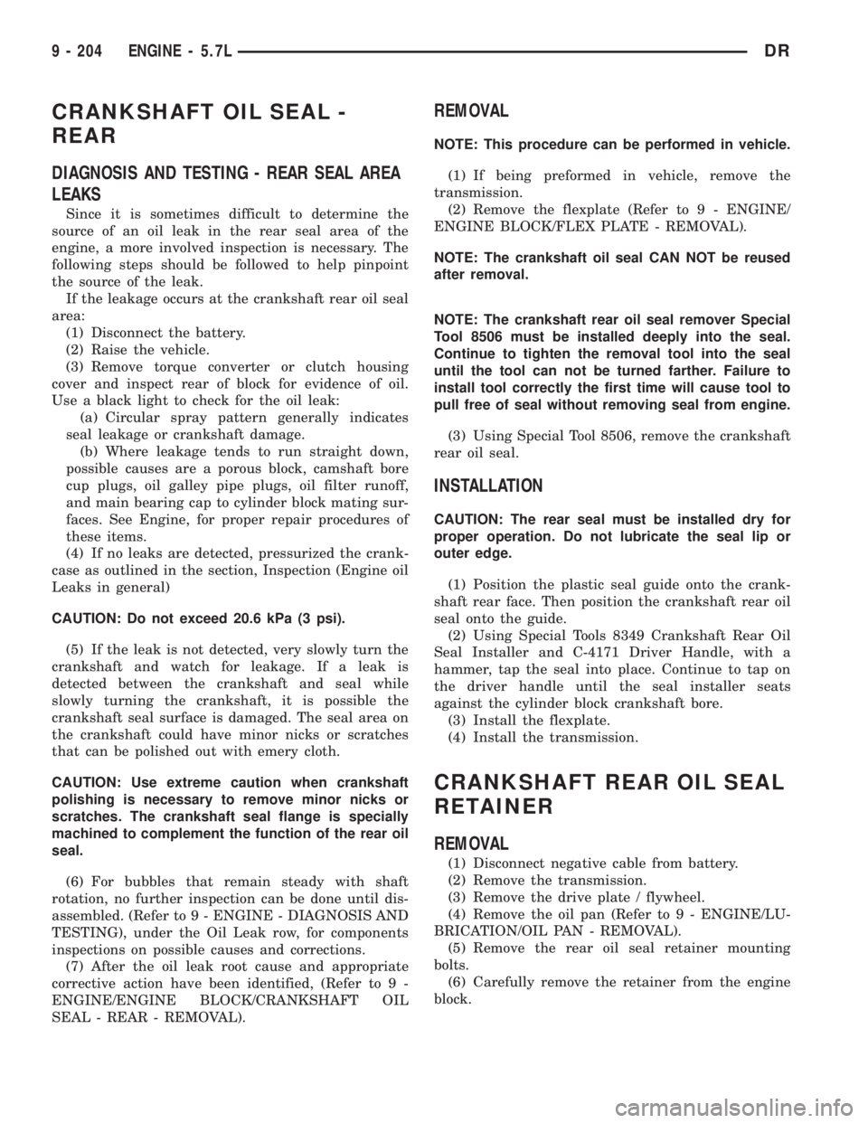
CRANKSHAFT OIL SEAL -
REAR
DIAGNOSIS AND TESTING - REAR SEAL AREA
LEAKS
Since it is sometimes difficult to determine the
source of an oil leak in the rear seal area of the
engine, a more involved inspection is necessary. The
following steps should be followed to help pinpoint
the source of the leak.
If the leakage occurs at the crankshaft rear oil seal
area:
(1) Disconnect the battery.
(2) Raise the vehicle.
(3) Remove torque converter or clutch housing
cover and inspect rear of block for evidence of oil.
Use a black light to check for the oil leak:
(a) Circular spray pattern generally indicates
seal leakage or crankshaft damage.
(b) Where leakage tends to run straight down,
possible causes are a porous block, camshaft bore
cup plugs, oil galley pipe plugs, oil filter runoff,
and main bearing cap to cylinder block mating sur-
faces. See Engine, for proper repair procedures of
these items.
(4) If no leaks are detected, pressurized the crank-
case as outlined in the section, Inspection (Engine oil
Leaks in general)
CAUTION: Do not exceed 20.6 kPa (3 psi).
(5) If the leak is not detected, very slowly turn the
crankshaft and watch for leakage. If a leak is
detected between the crankshaft and seal while
slowly turning the crankshaft, it is possible the
crankshaft seal surface is damaged. The seal area on
the crankshaft could have minor nicks or scratches
that can be polished out with emery cloth.
CAUTION: Use extreme caution when crankshaft
polishing is necessary to remove minor nicks or
scratches. The crankshaft seal flange is specially
machined to complement the function of the rear oil
seal.
(6) For bubbles that remain steady with shaft
rotation, no further inspection can be done until dis-
assembled. (Refer to 9 - ENGINE - DIAGNOSIS AND
TESTING), under the Oil Leak row, for components
inspections on possible causes and corrections.
(7) After the oil leak root cause and appropriate
corrective action have been identified, (Refer to 9 -
ENGINE/ENGINE BLOCK/CRANKSHAFT OIL
SEAL - REAR - REMOVAL).
REMOVAL
NOTE: This procedure can be performed in vehicle.
(1) If being preformed in vehicle, remove the
transmission.
(2) Remove the flexplate (Refer to 9 - ENGINE/
ENGINE BLOCK/FLEX PLATE - REMOVAL).
NOTE: The crankshaft oil seal CAN NOT be reused
after removal.
NOTE: The crankshaft rear oil seal remover Special
Tool 8506 must be installed deeply into the seal.
Continue to tighten the removal tool into the seal
until the tool can not be turned farther. Failure to
install tool correctly the first time will cause tool to
pull free of seal without removing seal from engine.
(3) Using Special Tool 8506, remove the crankshaft
rear oil seal.
INSTALLATION
CAUTION: The rear seal must be installed dry for
proper operation. Do not lubricate the seal lip or
outer edge.
(1) Position the plastic seal guide onto the crank-
shaft rear face. Then position the crankshaft rear oil
seal onto the guide.
(2) Using Special Tools 8349 Crankshaft Rear Oil
Seal Installer and C-4171 Driver Handle, with a
hammer, tap the seal into place. Continue to tap on
the driver handle until the seal installer seats
against the cylinder block crankshaft bore.
(3) Install the flexplate.
(4) Install the transmission.
CRANKSHAFT REAR OIL SEAL
RETAINER
REMOVAL
(1) Disconnect negative cable from battery.
(2) Remove the transmission.
(3) Remove the drive plate / flywheel.
(4) Remove the oil pan (Refer to 9 - ENGINE/LU-
BRICATION/OIL PAN - REMOVAL).
(5) Remove the rear oil seal retainer mounting
bolts.
(6) Carefully remove the retainer from the engine
block.
9 - 204 ENGINE - 5.7LDR