2003 DODGE RAM oil type
[x] Cancel search: oil typePage 491 of 2895
CAUTION: Do not leave any one spark plug cable
disconnected for longer than necessary during test-
ing. This may cause possible heat damage to the
catalytic converter. Total test time must not exceed
ten minutes.
Except 5.7L V-8 :With the engine running,
remove spark plug cable from spark plug (one at a
time) and hold next to a good engine ground. If the
cable and spark plug are in good condition, the
engine rpm should drop and the engine will run
poorly. If engine rpm does not drop, the cable and/or
spark plug may not be operating properly and should
be replaced. Also check engine cylinder compression.
With the engine not running, connect one end of a
test probe to a good ground. Start the engine and run
the other end of the test probe along the entire
length of all spark plug cables. If cables are cracked
or punctured, there will be a noticeable spark jump
from the damaged area to the test probe. The cable
running from the ignition coil to the distributor cap
can be checked in the same manner. Cracked, dam-
aged or faulty cables should be replaced with resis-
tance type cable. This can be identified by the words
ELECTRONIC SUPPRESSION printed on the cable
jacket.Use an ohmmeter to test for open circuits, exces-
sive resistance or loose terminals. If equipped,
remove the distributor cap from the distributor.Do
not remove cables from cap.Remove cable from
spark plug. Connect ohmmeter to spark plug termi-
nal end of cable and to corresponding electrode in
distributor cap. Resistance should be 250 to 1000
Ohms per inch of cable. If not, remove cable from dis-
tributor cap tower and connect ohmmeter to the ter-
minal ends of cable. If resistance is not within
specifications as found in the SPARK PLUG CABLE
RESISTANCE chart, replace the cable. Test all spark
plug cables in this manner.
SPARK PLUG CABLE RESISTANCE
MINIMUM MAXIMUM
250 Ohms Per Inch 1000 Ohms Per Inch
3000 Ohms Per Foot 12,000 Ohms Per Foot
To test ignition coil-to-distributor cap cable (if
applicaple), do not remove the cable from the cap.
Connect ohmmeter to rotor button (center contact) of
distributor cap and terminal at ignition coil end of
cable. If resistance is not within specifications as
found in the Spark Plug Cable Resistance chart,
remove the cable from the distributor cap. Connect
the ohmmeter to the terminal ends of the cable. If
resistance is not within specifications as found in the
Spark Plug Cable Resistance chart, replace the cable.
Inspect the ignition coil tower for cracks, burns or
corrosion.
REMOVAL
5.9L V-8 / 8.0L V-10
CAUTION: When disconnecting a high voltage cable
from a spark plug or from the distributor cap, twist
the rubber boot slightly (1/2 turn) to break it loose
(Fig. 54). Grasp the boot (not the cable) and pull it
off with a steady, even force.
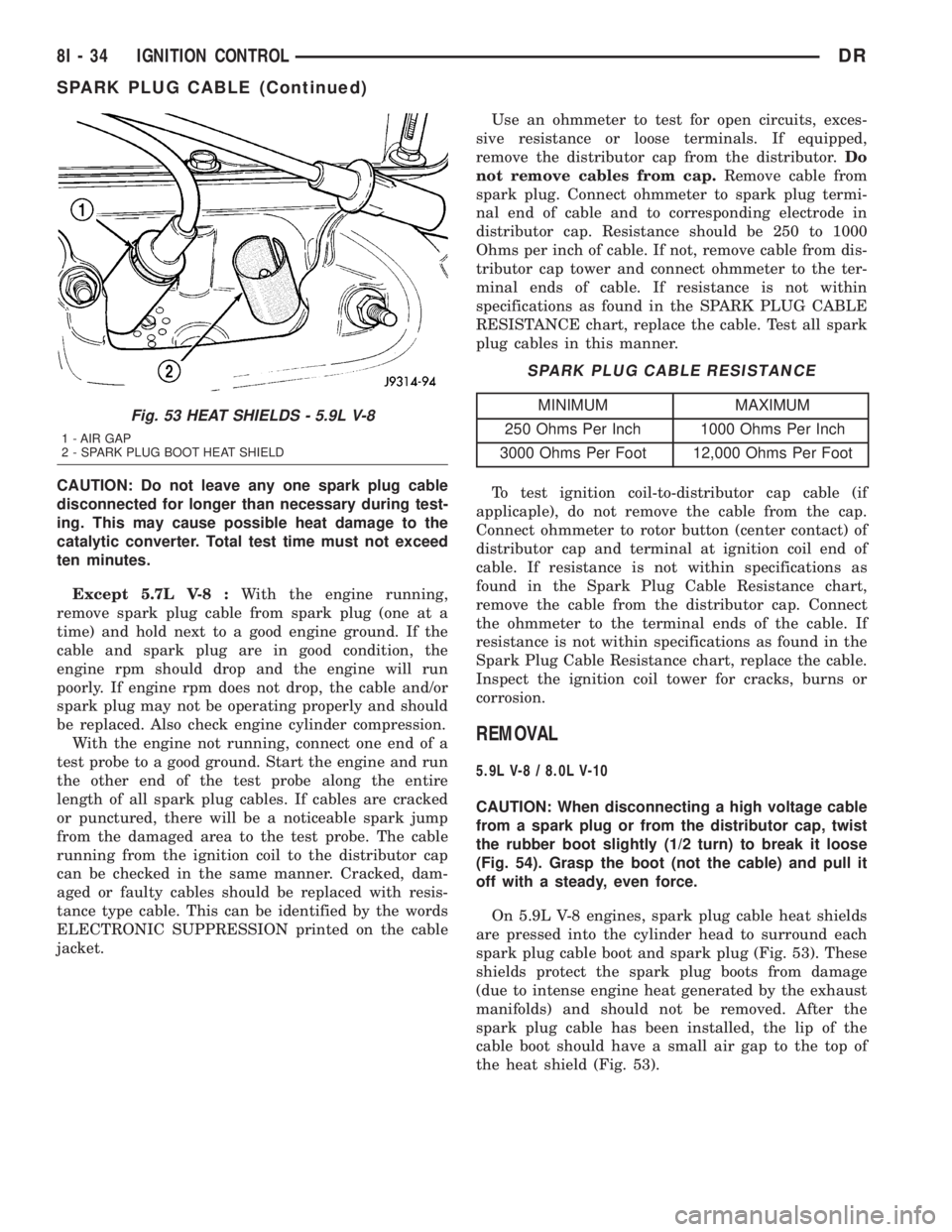
On 5.9L V-8 engines, spark plug cable heat shields
are pressed into the cylinder head to surround each
spark plug cable boot and spark plug (Fig. 53). These
shields protect the spark plug boots from damage
(due to intense engine heat generated by the exhaust
manifolds) and should not be removed. After the
spark plug cable has been installed, the lip of the
cable boot should have a small air gap to the top of
the heat shield (Fig. 53).
Fig. 53 HEAT SHIELDS - 5.9L V-8
1 - AIR GAP
2 - SPARK PLUG BOOT HEAT SHIELD
8I - 34 IGNITION CONTROLDR
SPARK PLUG CABLE (Continued)
Page 498 of 2895

the vehicle speed remains greater than about twenty-
four kilometers-per-hour (fifteen miles-per-hour).
²Vacuum Fluorescent Display Synchroniza-
tion- The EMIC transmits electronic panel lamp
dimming level messages which allows all other elec-
tronic modules on the PCI data bus with Vacuum
Fluorescent Display (VFD) units to coordinate their
illumination intensity with that of the EMIC VFD
units.
²Vehicle Theft Security System- The EMIC
monitors inputs from the door cylinder lock switch-
(es), the door ajar switches, the ignition switch, and
the Remote Keyless Entry (RKE) receiver module,
then provides electronic horn and lighting request
messages to the Front Control Module (FCM) located
on the Integrated Power Module (IPM) for the appro-
priate VTSS alarm output features.
²Wiper/Washer System Control- The EMIC
provides electronic wiper and/or washer request mes-
sages to the Front Control Module (FCM) located on
the Integrated Power Module (IPM) for the appropri-
ate wiper and washer system features. (Refer to 8 -
ELECTRICAL/WIPERS/WASHERS - DESCRIP-
TION).
The EMIC houses six analog gauges and has pro-
visions for up to twenty-three indicators (Fig. 3) or
(Fig. 4). The EMIC includes the following analog
gauges:
²Coolant Temperature Gauge
²Fuel Gauge
²Oil Pressure Gauge
²Speedometer
²Tachometer
²Voltage Gauge
Some of the EMIC indicators are automatically
configured when the EMIC is connected to the vehi-
cle electrical system for compatibility with certain
optional equipment or equipment required for regula-
tory purposes in certain markets. While each EMIC
may have provisions for indicators to support every
available option, the configurable indicators will not
be functional in a vehicle that does not have the
equipment that an indicator supports. The EMIC
includes provisions for the following indicators (Fig.
3) or (Fig. 4):
²Airbag Indicator (with Airbag System only)
²Antilock Brake System (ABS) Indicator
(with ABS or Rear Wheel Anti-Lock [RWAL]
brakes only)
²Brake Indicator
²Cargo Lamp Indicator
²Check Gauges Indicator
²Cruise Indicator (with Speed Control only)
²Door Ajar Indicator
²Electronic Throttle Control (ETC) Indicator
(with 5.7L Gasoline Engine only)²Gear Selector Indicator (with Automatic
Transmission only)
²High Beam Indicator
²Lamp Out Indicator
²Low Fuel Indicator
²Malfunction Indicator Lamp (MIL)
²Overdrive-Off Indicator (with Automatic
Transmission only)
²Seatbelt Indicator
²Security Indicator (with Sentry Key Immo-
bilizer & Vehicle Theft Security Systems only)
²Service Four-Wheel Drive Indicator (with
Four-Wheel Drive only)
²Transmission Overtemp Indicator (with
Automatic Transmission only)
²Turn Signal (Right and Left) Indicators
²Upshift Indicator (with Manual Transmis-
sion only)
²Washer Fluid Indicator
²Wait-To-Start Indicator (with Diesel Engine
only)
²Water-In-Fuel Indicator (with Diesel Engine
only)
Each indicator in the EMIC, except those located
within one of the VFD units, is illuminated by a ded-
icated LED that is soldered onto the EMIC electronic
circuit board. The LED units are not available for
service replacement and, if damaged or faulty, the
entire EMIC must be replaced. Cluster illumination
is accomplished by dimmable incandescent back
lighting, which illuminates the gauges for visibility
when the exterior lighting is turned on. Each of the
incandescent bulbs is secured by an integral bulb
holder to the electronic circuit board from the back of
the cluster housing.
Hard wired circuitry connects the EMIC to the
electrical system of the vehicle. These hard wired cir-
cuits are integral to several wire harnesses, which
are routed throughout the vehicle and retained by
many different methods. These circuits may be con-
nected to each other, to the vehicle electrical system
and to the EMIC through the use of a combination of
soldered splices, splice block connectors, and many
different types of wire harness terminal connectors
and insulators. Refer to the appropriate wiring infor-
mation. The wiring information includes wiring dia-
grams, proper wire and connector repair procedures,
further details on wire harness routing and reten-
tion, as well as pin-out and location views for the
various wire harness connectors, splices and grounds.
The EMIC modules for this model are serviced only
as complete units. The EMIC module cannot be
adjusted or repaired. If a gauge, an LED indicator, a
VFD unit, the electronic circuit board, the circuit
board hardware, the cluster overlay, or the EMIC
housing are damaged or faulty, the entire EMIC mod-
DRINSTRUMENT CLUSTER 8J - 5
INSTRUMENT CLUSTER (Continued)
Page 544 of 2895

STANDARD PROCEDURE
SAFETY PRECAUTIONS
WARNING: EYE PROTECTION SHOULD BE USED
WHEN SERVICING GLASS COMPONENTS. PER-
SONAL INJURY CAN RESULT.
CAUTION: Do not touch the glass of halogen bulbs
with fingers or other possibly oily surface, reduced
bulb life will result.Do not use bulbs with higher
candle power than indicated in the Bulb Application
table . Damage to lamp and/or Daytime Running
Lamp Module can result.Do not use fuses, circuit
breakers or relays having greater amperage value
than indicated on the fuse panel or in the Owners
Manual.
When it is necessary to remove components to ser-
vice another, it should not be necessary to apply
excessive force or bend a component to remove it.
Before damaging a trim component, verify hidden
fasteners or captured edges are not holding the com-
ponent in place.
SPECIFICATIONS
EXTERIOR LAMPS
CAUTION: Do not use bulbs that have a higher can-
dle power than the bulb listed in the Bulb Applica-
tion Table. Damage to lamp can result. Do not touch
halogen bulbs with fingers or other oily surfaces.
Bulb life will be reduced.
The following Bulb Application Table lists the lamp
title on the left side of the column and trade number
or part number on the right.
BULB APPLICATION TABLE
LAMP BULB
Back-up 3157
Center High Mounted
Stop lamp912
Fog lamp 9006LL
Front Park/Turn Signal 4157NAK
Head lamp 9007
License Plate 7F69
Tail, Brake, Turn Signal 3157
Side Marker, Tail Gate,
Cab Clearance168
SPECIAL TOOLS - HEADLAMP ALIGNMENT
BACKUP LAMP
REMOVAL
(1) Remove and isolate the negitive battery cable.
(2) Remove the taillamp unit (Refer to 8 - ELEC-
TRICAL/LAMPS/LIGHTING - EXTERIOR/TAIL
LAMP UNIT - REMOVAL).
(3) Remove the bulb back plate from the tail lamp
unit.
(4) Separate the bulb from the socket.
INSTALLATION
(1) Install the bulb into the socket.
(2) Install the bulb back plate to the tail lamp
unit.
(3) Install the tail lamp unit (Refer to 8 - ELEC-
TRICAL/LAMPS/LIGHTING - EXTERIOR/TAIL
LAMP UNIT - INSTALLATION).
(4) Reconnect the negative battery cable.
BACKUP LAMP SWITCH
DESCRIPTION
Vehicles equipped with a manual transmission
have a normally open, spring-loaded plunger type
back-up lamp switch (Fig. 1). The backup lamp
switch is located in a threaded hole on the side of the
manual transmission housing. The backup lamp
switch has a threaded body and a hex formation near
the plunger end of the switch, and an integral con-
nector at the opposite end of the switch. When
installed, only the connector and the hex formation
are visible on the outside of the transmission hous-
ing. Vehicles with an optional electronic automatic
transmission have a Transmission Range Sensor
(TRS) that is used to perform several functions,
including that of the backup lamp switch. The TRS is
described in further detail elsewhere in this service
information. The backup lamp switch cannot be
adjusted or repaired and, if faulty or damaged, the
entire switch unit must be replaced.
Headlamp Aiming Kit C-4466±A
DRLAMPS/LIGHTING - EXTERIOR 8L - 7
LAMPS/LIGHTING - EXTERIOR (Continued)
Page 549 of 2895

(ISO) micro relay (Fig. 7). Relays conforming to the
ISO specifications have common physical dimensions,
current capacities, terminal patterns, and terminal
functions. The relay is contained within a small, rect-
angular, molded plastic housing and is connected to
all of the required inputs and outputs by five integral
male spade-type terminals that extend from the bot-
tom of the relay base.
The front fog lamp relay cannot be adjusted or
repaired and, if faulty or damaged, the unit must be
replaced.
OPERATION
The front fog lamp relay is an electromechanical
switch that uses a low current input from the Front
Control Module (FCM) to control a high current out-
put to the front fog lamps. The movable common feed
contact point is held against the fixed normally
closed contact point by spring pressure. When the
relay coil is energized, an electromagnetic field is
produced by the coil windings. This electromagnetic
field draws the movable relay contact point away
from the fixed normally closed contact point, and
holds it against the fixed normally open contact
point. When the relay coil is de-energized, spring
pressure returns the movable contact point back
against the fixed normally closed contact point. A
resistor is connected in parallel with the relay coil in
the relay, and helps to dissipate voltage spikes and
electromagnetic interference that can be generated as
the electromagnetic field of the relay coil collapses.
The front fog lamp relay terminals are connected
to the vehicle electrical system through a connector
receptacle in the Power Distribution Center (PDC).
The inputs and outputs of the front fog lamp relay
include:
²Common Feed Terminal- The common feed
terminal (30) receives battery voltage at all times
from a fuse in the PDC through a fused B(+) circuit.
²Coil Ground Terminal- The coil ground termi-
nal (85) is connected to a control output of the Front
Control Module (FCM) through a front fog lamp relay
control circuit. The FCM controls front fog lamp oper-
ation by controlling a ground path through this cir-
cuit.
²Coil Battery Terminal- The coil battery ter-
minal (86) receives battery voltage at all times from
a fuse in the PDC through a fused B(+) circuit.
²Normally Open Terminal- The normally open
terminal (87) is connected to the front fog lamps
through a front fog lamp relay output circuit and
provides battery voltage to the front fog lamps when-
ever the relay is energized.
²Normally Closed Terminal- The normally
closed terminal (87A) is not connected in this appli-
cation.The front fog lamp relay can be diagnosed using
conventional diagnostic tools and methods.
DIAGNOSIS AND TESTING - FRONT FOG LAMP
RELAY
The front fog lamp relay (Fig. 8) is located in the
Power Distribution Center in the engine compart-
ment. Refer to the appropriate wiring information.
WARNING: ON VEHICLES EQUIPPED WITH AIR-
BAGS, DISABLE THE SUPPLEMENTAL RESTRAINT
SYSTEM BEFORE ATTEMPTING ANY STEERING
WHEEL, STEERING COLUMN, DRIVER AIRBAG,
PASSENGER AIRBAG, SEAT BELT TENSIONER,
FRONT IMPACT SENSORS, SIDE CURTAIN AIRBAG,
OR INSTRUMENT PANEL COMPONENT DIAGNOSIS
OR SERVICE. DISCONNECT AND ISOLATE THE
BATTERY NEGATIVE (GROUND) CABLE, THEN
WAIT TWO MINUTES FOR THE SYSTEM CAPACI-
TOR TO DISCHARGE BEFORE PERFORMING FUR-
THER DIAGNOSIS OR SERVICE. THIS IS THE ONLY
SURE WAY TO DISABLE THE SUPPLEMENTAL
RESTRAINT SYSTEM. FAILURE TO TAKE THE
PROPER PRECAUTIONS COULD RESULT IN ACCI-
DENTAL AIRBAG DEPLOYMENT AND POSSIBLE
PERSONAL INJURY.
(1) Remove the front fog lamp relay from the PDC.
(Refer to 8 - ELECTRICAL/LAMPS/LIGHTING -
EXTERIOR/FRONT FOG LAMP RELAY - REMOV-
AL).
(2) A relay in the de-energized position should
have continuity between terminals 87A and 30, and
no continuity between terminals 87 and 30. If OK, go
to Step 3. If not OK, replace the faulty relay.
Fig. 8 ISO Micro Relay
30 - COMMON FEED
85 - COIL GROUND
86 - COIL BATTERY
87 - NORMALLY OPEN
87A - NORMALLY CLOSED
8L - 12 LAMPS/LIGHTING - EXTERIORDR
FOG LAMP RELAY (Continued)
Page 695 of 2895
(3) Extract the hook formation on the tip of the
wiper arm through the opening in the wiper blade
superstructure just ahead of the wiper blade pivot
block/latch unit.
CAUTION: Do not allow the wiper arm to spring
back against the glass without the wiper blade in
place or the glass may be damaged.
(4) Gently lower the tip of the wiper arm onto the
glass.
INSTALLATION
NOTE: The notched end of the wiper element flexor
should always be oriented towards the end of the
wiper blade that is nearest to the wiper pivot.
(1)
Lift the wiper arm off of the windshield glass,
until the wiper arm hinge is in its over-center position.
(2) Position the wiper blade near the hook forma-
tion on the tip of the arm with the notched end of the
wiper element flexor oriented towards the end of the
wiper arm that is nearest to the wiper pivot.
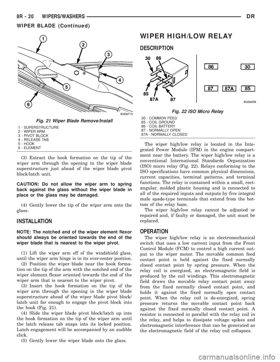
(3) Insert the hook formation on the tip of the
wiper arm through the opening in the wiper blade
superstructure ahead of the wiper blade pivot block/
latch unit far enough to engage the pivot block into
the hook (Fig. 21).
(4) Slide the wiper blade pivot block/latch up into
the hook formation on the tip of the wiper arm until
the latch release tab snaps into its locked position.
Latch engagement will be accompanied by an audible
click.
(5) Gently lower the wiper blade onto the glass.
WIPER HIGH/LOW RELAY
DESCRIPTION
The wiper high/low relay is located in the Inte-
grated Power Module (IPM) in the engine compart-
ment near the battery. The wiper high/low relay is a
conventional International Standards Organization
(ISO) micro relay (Fig. 22). Relays conforming to the
ISO specifications have common physical dimensions,
current capacities, terminal patterns, and terminal
functions. The relay is contained within a small, rect-
angular, molded plastic housing and is connected to
all of the required inputs and outputs by five integral
male spade-type terminals that extend from the bot-
tom of the relay base.
The wiper high/low relay cannot be adjusted or
repaired and, if faulty or damaged, the unit must be
replaced.
OPERATION
The wiper high/low relay is an electromechanical
switch that uses a low current input from the Front
Control Module (FCM) to control a high current out-
put to the wiper motor. The movable common feed
contact point is held against the fixed normally
closed contact point by spring pressure. When the
relay coil is energized, an electromagnetic field is
produced by the coil windings. This electromagnetic
field draws the movable relay contact point away
from the fixed normally closed contact point, and
holds it against the fixed normally open contact
point. When the relay coil is de-energized, spring
pressure returns the movable contact point back
against the fixed normally closed contact point. A
resistor is connected in parallel with the relay coil in
the relay, and helps to dissipate voltage spikes and
electromagnetic interference that can be generated as
the electromagnetic field of the relay coil collapses.
Fig. 21 Wiper Blade Remove/Install
1 - SUPERSTRUCTURE
2 - WIPER ARM
3 - PIVOT BLOCK
4 - RELEASE TAB
5 - HOOK
6 - ELEMENT
Fig. 22 ISO Micro Relay
30 - COMMON FEED
85 - COIL GROUND
86 - COIL BATTERY
87 - NORMALLY OPEN
87A - NORMALLY CLOSED
8R - 20 WIPERS/WASHERSDR
WIPER BLADE (Continued)
Page 700 of 2895
WIPER ON/OFF RELAY
DESCRIPTION
The wiper on/off relay is located in the Integrated
Power Module (IPM) in the engine compartment near
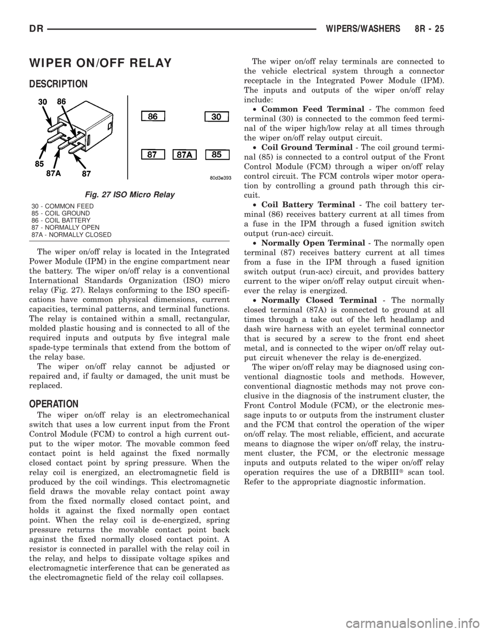
the battery. The wiper on/off relay is a conventional
International Standards Organization (ISO) micro
relay (Fig. 27). Relays conforming to the ISO specifi-
cations have common physical dimensions, current
capacities, terminal patterns, and terminal functions.
The relay is contained within a small, rectangular,
molded plastic housing and is connected to all of the
required inputs and outputs by five integral male
spade-type terminals that extend from the bottom of
the relay base.
The wiper on/off relay cannot be adjusted or
repaired and, if faulty or damaged, the unit must be
replaced.
OPERATION
The wiper on/off relay is an electromechanical
switch that uses a low current input from the Front
Control Module (FCM) to control a high current out-
put to the wiper motor. The movable common feed
contact point is held against the fixed normally
closed contact point by spring pressure. When the
relay coil is energized, an electromagnetic field is
produced by the coil windings. This electromagnetic
field draws the movable relay contact point away
from the fixed normally closed contact point, and
holds it against the fixed normally open contact
point. When the relay coil is de-energized, spring
pressure returns the movable contact point back
against the fixed normally closed contact point. A
resistor is connected in parallel with the relay coil in
the relay, and helps to dissipate voltage spikes and
electromagnetic interference that can be generated as
the electromagnetic field of the relay coil collapses.The wiper on/off relay terminals are connected to
the vehicle electrical system through a connector
receptacle in the Integrated Power Module (IPM).
The inputs and outputs of the wiper on/off relay
include:
²Common Feed Terminal- The common feed
terminal (30) is connected to the common feed termi-
nal of the wiper high/low relay at all times through
the wiper on/off relay output circuit.
²Coil Ground Terminal- The coil ground termi-
nal (85) is connected to a control output of the Front
Control Module (FCM) through a wiper on/off relay
control circuit. The FCM controls wiper motor opera-
tion by controlling a ground path through this cir-
cuit.
²Coil Battery Terminal- The coil battery ter-
minal (86) receives battery current at all times from
a fuse in the IPM through a fused ignition switch
output (run-acc) circuit.
²Normally Open Terminal- The normally open
terminal (87) receives battery current at all times
from a fuse in the IPM through a fused ignition
switch output (run-acc) circuit, and provides battery
current to the wiper on/off relay output circuit when-
ever the relay is energized.
²Normally Closed Terminal- The normally
closed terminal (87A) is connected to ground at all
times through a take out of the left headlamp and
dash wire harness with an eyelet terminal connector
that is secured by a screw to the front end sheet
metal, and is connected to the wiper on/off relay out-
put circuit whenever the relay is de-energized.
The wiper on/off relay may be diagnosed using con-
ventional diagnostic tools and methods. However,
conventional diagnostic methods may not prove con-
clusive in the diagnosis of the instrument cluster, the
Front Control Module (FCM), or the electronic mes-
sage inputs to or outputs from the instrument cluster
and the FCM that control the operation of the wiper
on/off relay. The most reliable, efficient, and accurate
means to diagnose the wiper on/off relay, the instru-
ment cluster, the FCM, or the electronic message
inputs and outputs related to the wiper on/off relay
operation requires the use of a DRBIIItscan tool.
Refer to the appropriate diagnostic information.
Fig. 27 ISO Micro Relay
30 - COMMON FEED
85 - COIL GROUND
86 - COIL BATTERY
87 - NORMALLY OPEN
87A - NORMALLY CLOSED
DRWIPERS/WASHERS 8R - 25
Page 1248 of 2895
DIAGNOSIS & TESTING - RELAY CIRCUIT TEST
(1) The relay common feed terminal cavity (30) of
the integrated power module is connected to battery
voltage and should be hot at all times. Check for bat-
tery voltage at the fused B(+) circuit cavity in the
integrated power module receptacle for the relay. If
OK, go to Step 2. If not OK, repair the fused B(+) cir-
cuit to the integrated power module fuse as required.
(2) The relay normally closed terminal (87A) is
connected to terminal 30 in the de-energized position,
but is not used for this application. Go to Step 3.
(3) The relay normally open terminal (87) is con-
nected to the common feed terminal (30) in the ener-
gized position. This terminal supplies battery voltage
to the fused B(+) fuse in the integrated power module
that feeds the accessory when the relay is energized
by the ignition switch. There should be continuity
between the integrated power module cavity for relay
terminal 87 and the fused B(+) fuse in the integrated
power module at all times. If OK, go to Step 4. If not
OK, repair the open fused B(+) circuit to the inte-
grated power module fuse as required.
(4) The coil ground terminal (85) is connected to
the electromagnet in the relay. It receives battery
feed to energize the relay when the ignition switch is
in the Accessory or Run positions. Turn the ignition
switch to the On position. Check for battery voltage
at the fused ignition switch output (acc/run) circuit
cavity for relay terminal 85 in the integrated power
module receptacle for the relay. If OK, go to Step 5. If
not OK, repair the open fused ignition switch output
(acc/run) circuit to the ignition switch as required.
(5) The coil battery terminal (86) is connected to
the electromagnet in the relay. The integrated power
module cavity for this terminal should have continu-
ity to ground at all times. If not OK, repair the open
ground circuit to ground as required.
REMOVAL
(1) Disconnect and isolate the negative battery
cable.
(2) Remove the relay by grasping it firmly and
pulling it straight out from its receptacle. A slight
back and fourth rocking motion may help the
removal process.
INSTALLATION
(1) Position the relay to the proper receptacle.
(2) Align the relay terminals with the terminal
cavities in the receptacle.
(3) Push firmly and evenly on the top of the relay
until the terminals are fully seated in the terminal
cavities in the receptacle.
(4) Connect the negative battery cable.
MICRO RELAY
DESCRIPTION
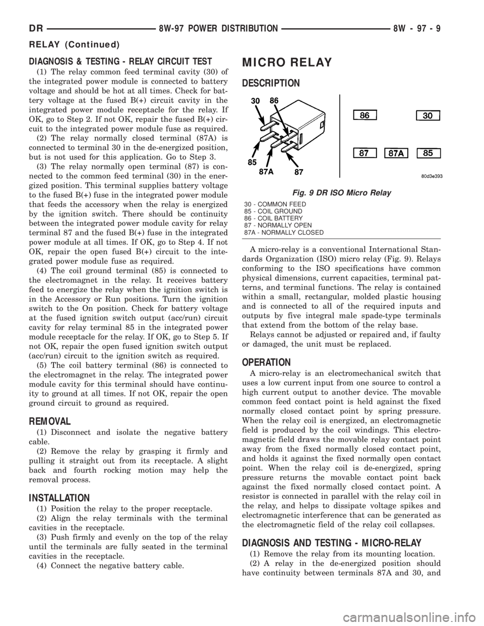
A micro-relay is a conventional International Stan-
dards Organization (ISO) micro relay (Fig. 9). Relays
conforming to the ISO specifications have common
physical dimensions, current capacities, terminal pat-
terns, and terminal functions. The relay is contained
within a small, rectangular, molded plastic housing
and is connected to all of the required inputs and
outputs by five integral male spade-type terminals
that extend from the bottom of the relay base.
Relays cannot be adjusted or repaired and, if faulty
or damaged, the unit must be replaced.
OPERATION
A micro-relay is an electromechanical switch that
uses a low current input from one source to control a
high current output to another device. The movable
common feed contact point is held against the fixed
normally closed contact point by spring pressure.
When the relay coil is energized, an electromagnetic
field is produced by the coil windings. This electro-
magnetic field draws the movable relay contact point
away from the fixed normally closed contact point,
and holds it against the fixed normally open contact
point. When the relay coil is de-energized, spring
pressure returns the movable contact point back
against the fixed normally closed contact point. A
resistor is connected in parallel with the relay coil in
the relay, and helps to dissipate voltage spikes and
electromagnetic interference that can be generated as
the electromagnetic field of the relay coil collapses.
DIAGNOSIS AND TESTING - MICRO-RELAY
(1) Remove the relay from its mounting location.
(2) A relay in the de-energized position should
have continuity between terminals 87A and 30, and
Fig. 9 DR ISO Micro Relay
30 - COMMON FEED
85 - COIL GROUND
86 - COIL BATTERY
87 - NORMALLY OPEN
87A - NORMALLY CLOSED
DR8W-97 POWER DISTRIBUTION 8W - 97 - 9
RELAY (Continued)
Page 1258 of 2895
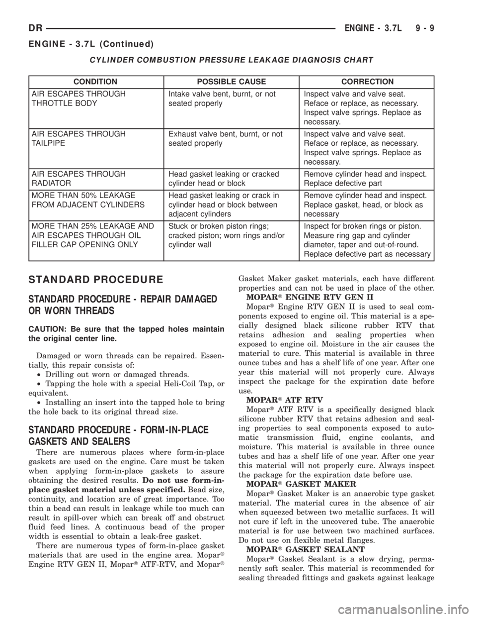
CYLINDER COMBUSTION PRESSURE LEAKAGE DIAGNOSIS CHART
CONDITION POSSIBLE CAUSE CORRECTION
AIR ESCAPES THROUGH
THROTTLE BODYIntake valve bent, burnt, or not
seated properlyInspect valve and valve seat.
Reface or replace, as necessary.
Inspect valve springs. Replace as
necessary.
AIR ESCAPES THROUGH
TAILPIPEExhaust valve bent, burnt, or not
seated properlyInspect valve and valve seat.
Reface or replace, as necessary.
Inspect valve springs. Replace as
necessary.
AIR ESCAPES THROUGH
RADIATORHead gasket leaking or cracked
cylinder head or blockRemove cylinder head and inspect.
Replace defective part
MORE THAN 50% LEAKAGE
FROM ADJACENT CYLINDERSHead gasket leaking or crack in
cylinder head or block between
adjacent cylindersRemove cylinder head and inspect.
Replace gasket, head, or block as
necessary
MORE THAN 25% LEAKAGE AND
AIR ESCAPES THROUGH OIL
FILLER CAP OPENING ONLYStuck or broken piston rings;
cracked piston; worn rings and/or
cylinder wallInspect for broken rings or piston.
Measure ring gap and cylinder
diameter, taper and out-of-round.
Replace defective part as necessary
STANDARD PROCEDURE
STANDARD PROCEDURE - REPAIR DAMAGED
OR WORN THREADS
CAUTION: Be sure that the tapped holes maintain
the original center line.
Damaged or worn threads can be repaired. Essen-
tially, this repair consists of:
²Drilling out worn or damaged threads.
²Tapping the hole with a special Heli-Coil Tap, or
equivalent.
²Installing an insert into the tapped hole to bring
the hole back to its original thread size.
STANDARD PROCEDURE - FORM-IN-PLACE
GASKETS AND SEALERS
There are numerous places where form-in-place
gaskets are used on the engine. Care must be taken
when applying form-in-place gaskets to assure
obtaining the desired results.Do not use form-in-
place gasket material unless specified.Bead size,
continuity, and location are of great importance. Too
thin a bead can result in leakage while too much can
result in spill-over which can break off and obstruct
fluid feed lines. A continuous bead of the proper
width is essential to obtain a leak-free gasket.
There are numerous types of form-in-place gasket
materials that are used in the engine area. Mopart
Engine RTV GEN II, MopartATF-RTV, and MopartGasket Maker gasket materials, each have different
properties and can not be used in place of the other.
MOPARtENGINE RTV GEN II
MopartEngine RTV GEN II is used to seal com-
ponents exposed to engine oil. This material is a spe-
cially designed black silicone rubber RTV that
retains adhesion and sealing properties when
exposed to engine oil. Moisture in the air causes the
material to cure. This material is available in three
ounce tubes and has a shelf life of one year. After one
year this material will not properly cure. Always
inspect the package for the expiration date before
use.
MOPARtATF RTV
MopartATF RTV is a specifically designed black
silicone rubber RTV that retains adhesion and seal-
ing properties to seal components exposed to auto-
matic transmission fluid, engine coolants, and
moisture. This material is available in three ounce
tubes and has a shelf life of one year. After one year
this material will not properly cure. Always inspect
the package for the expiration date before use.
MOPARtGASKET MAKER
MopartGasket Maker is an anaerobic type gasket
material. The material cures in the absence of air
when squeezed between two metallic surfaces. It will
not cure if left in the uncovered tube. The anaerobic
material is for use between two machined surfaces.
Do not use on flexible metal flanges.
MOPARtGASKET SEALANT
MopartGasket Sealant is a slow drying, perma-
nently soft sealer. This material is recommended for
sealing threaded fittings and gaskets against leakage
DRENGINE - 3.7L 9 - 9
ENGINE - 3.7L (Continued)