2003 DODGE RAM Blend door
[x] Cancel search: Blend doorPage 2795 of 2895
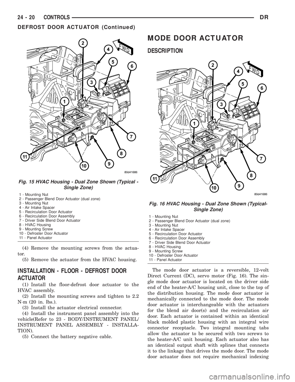
(4) Remove the mounting screws from the actua-
tor.
(5) Remove the actuator from the HVAC housing.
INSTALLATION - FLOOR - DEFROST DOOR
ACTUATOR
(1) Install the floor-defrost door actuator to the
HVAC assembly.
(2) Install the mounting screws and tighten to 2.2
N´m (20 in. lbs.).
(3) Install the actuator electrical connector.
(4) Install the instrument panel assembly into the
vehicle(Refer to 23 - BODY/INSTRUMENT PANEL/
INSTRUMENT PANEL ASSEMBLY - INSTALLA-
TION).
(5) Connect the battery negative cable.
MODE DOOR ACTUATOR
DESCRIPTION
The mode door actuator is a reversible, 12-volt
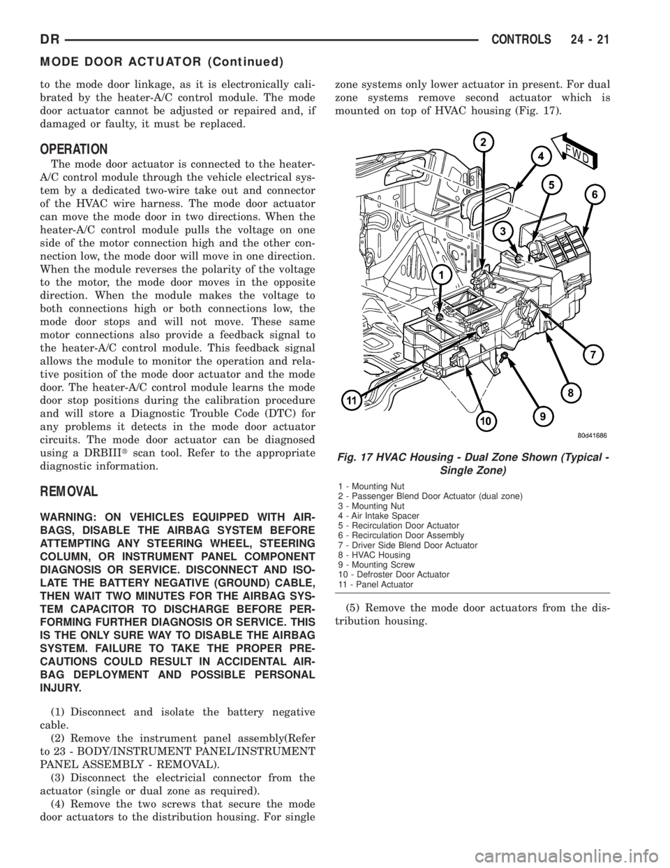
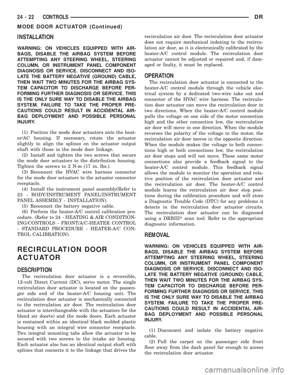
Direct Current (DC), servo motor (Fig. 16). The sin-
gle mode door actuator is located on the driver side
end of the heater-A/C housing unit, close to the top of
the distribution housing. The mode door actuator is
mechanically connected to the mode door. The mode
door actuator is interchangeable with the actuators
for the blend air door(s) and the recirculation air
door. Each actuator is contained within an identical
black molded plastic housing with an integral wire
connector receptacle. Two integral mounting tabs
allow the actuator to be secured with two screws to
the heater-A/C unit housing. Each actuator also has
an identical output shaft with splines that connects
it to the linkage that drives the mode door. The mode
door actuator does not require mechanical indexing
Fig. 15 HVAC Housing - Dual Zone Shown (Typical -
Single Zone)
1 - Mounting Nut
2 - Passenger Blend Door Actuator (dual zone)
3 - Mounting Nut
4 - Air Intake Spacer
5 - Recirculation Door Actuator
6 - Recirculation Door Assembly
7 - Driver Side Blend Door Actuator
8 - HVAC Housing
9 - Mounting Screw
10 - Defroster Door Actuator
11 - Panel Actuator
Fig. 16 HVAC Housing - Dual Zone Shown (Typical-
Single Zone)
1 - Mounting Nut
2 - Passenger Blend Door Actuator (dual zone)
3 - Mounting Nut
4 - Air Intake Spacer
5 - Recirculation Door Actuator
6 - Recirculation Door Assembly
7 - Driver Side Blend Door Actuator
8 - HVAC Housing
9 - Mounting Screw
10 - Defroster Door Actuator
11 - Panel Actuator
24 - 20 CONTROLSDR
DEFROST DOOR ACTUATOR (Continued)
Page 2796 of 2895
to the mode door linkage, as it is electronically cali-
brated by the heater-A/C control module. The mode
door actuator cannot be adjusted or repaired and, if
damaged or faulty, it must be replaced.
OPERATION
The mode door actuator is connected to the heater-
A/C control module through the vehicle electrical sys-
tem by a dedicated two-wire take out and connector
of the HVAC wire harness. The mode door actuator
can move the mode door in two directions. When the
heater-A/C control module pulls the voltage on one
side of the motor connection high and the other con-
nection low, the mode door will move in one direction.
When the module reverses the polarity of the voltage
to the motor, the mode door moves in the opposite
direction. When the module makes the voltage to
both connections high or both connections low, the
mode door stops and will not move. These same
motor connections also provide a feedback signal to
the heater-A/C control module. This feedback signal
allows the module to monitor the operation and rela-
tive position of the mode door actuator and the mode
door. The heater-A/C control module learns the mode
door stop positions during the calibration procedure
and will store a Diagnostic Trouble Code (DTC) for
any problems it detects in the mode door actuator
circuits. The mode door actuator can be diagnosed
using a DRBIIItscan tool. Refer to the appropriate
diagnostic information.
REMOVAL
WARNING: ON VEHICLES EQUIPPED WITH AIR-
BAGS, DISABLE THE AIRBAG SYSTEM BEFORE
ATTEMPTING ANY STEERING WHEEL, STEERING
COLUMN, OR INSTRUMENT PANEL COMPONENT
DIAGNOSIS OR SERVICE. DISCONNECT AND ISO-
LATE THE BATTERY NEGATIVE (GROUND) CABLE,
THEN WAIT TWO MINUTES FOR THE AIRBAG SYS-
TEM CAPACITOR TO DISCHARGE BEFORE PER-
FORMING FURTHER DIAGNOSIS OR SERVICE. THIS
IS THE ONLY SURE WAY TO DISABLE THE AIRBAG
SYSTEM. FAILURE TO TAKE THE PROPER PRE-
CAUTIONS COULD RESULT IN ACCIDENTAL AIR-
BAG DEPLOYMENT AND POSSIBLE PERSONAL
INJURY.
(1) Disconnect and isolate the battery negative
cable.
(2) Remove the instrument panel assembly(Refer
to 23 - BODY/INSTRUMENT PANEL/INSTRUMENT
PANEL ASSEMBLY - REMOVAL).
(3) Disconnect the electricial connector from the
actuator (single or dual zone as required).
(4) Remove the two screws that secure the mode
door actuators to the distribution housing. For singlezone systems only lower actuator in present. For dual
zone systems remove second actuator which is
mounted on top of HVAC housing (Fig. 17).
(5) Remove the mode door actuators from the dis-
tribution housing.
Fig. 17 HVAC Housing - Dual Zone Shown (Typical -
Single Zone)
1 - Mounting Nut
2 - Passenger Blend Door Actuator (dual zone)
3 - Mounting Nut
4 - Air Intake Spacer
5 - Recirculation Door Actuator
6 - Recirculation Door Assembly
7 - Driver Side Blend Door Actuator
8 - HVAC Housing
9 - Mounting Screw
10 - Defroster Door Actuator
11 - Panel Actuator
DRCONTROLS 24 - 21
MODE DOOR ACTUATOR (Continued)
Page 2797 of 2895
INSTALLATION
WARNING: ON VEHICLES EQUIPPED WITH AIR-
BAGS, DISABLE THE AIRBAG SYSTEM BEFORE
ATTEMPTING ANY STEERING WHEEL, STEERING
COLUMN, OR INSTRUMENT PANEL COMPONENT
DIAGNOSIS OR SERVICE. DISCONNECT AND ISO-
LATE THE BATTERY NEGATIVE (GROUND) CABLE,
THEN WAIT TWO MINUTES FOR THE AIRBAG SYS-
TEM CAPACITOR TO DISCHARGE BEFORE PER-
FORMING FURTHER DIAGNOSIS OR SERVICE. THIS
IS THE ONLY SURE WAY TO DISABLE THE AIRBAG
SYSTEM. FAILURE TO TAKE THE PROPER PRE-
CAUTIONS COULD RESULT IN ACCIDENTAL AIR-
BAG DEPLOYMENT AND POSSIBLE PERSONAL
INJURY.
(1) Position the mode door actuators onto the heat-
er/AC housing. If necessary, rotate the actuator
slightly to align the splines on the actuator output
shaft with those in the mode door linkage.
(2) Install and tighten the two screws that secure
the mode door actuators to the distribution housing.
Tighten the screws to 2 N´m (17 in. lbs.).
(3) Reconnect the HVAC wire harness connector
for the mode door actuators to the actuator connector
receptacle.
(4) Install the instrument panel assembly(Refer to
23 - BODY/INSTRUMENT PANEL/INSTRUMENT
PANEL ASSEMBLY - INSTALLATION).
(5) Reconnect the battery negative cable.
(6) Perform the heater-A/C control calibration pro-
cedure. (Refer to 24 - HEATING & AIR CONDITION-
ING/CONTROLS - FRONT/A/C-HEATER CONTROL
- STANDARD PROCEDURE - HEATER-A/C CON-
TROL CALIBRATION).
RECIRCULATION DOOR
ACTUATOR
DESCRIPTION
The recirculation door actuator is a reversible,
12-volt Direct Current (DC), servo motor. The single
recirculation door actuator is located on the passen-
ger side end of the heater-A/C housing unit. The
recirculation door actuator is mechanically connected
to the recirculation air door. The recirculation door
actuator is interchangeable with the actuators for the
blend air door(s) and the mode doors. Each actuator
is contained within an identical black molded plastic
housing with an integral wire connector receptacle.
Two integral mounting tabs allow the actuator to be
secured with two screws to the intake air housing.
Each actuator also has an identical output shaft with
splines that connects it to the linkage that drives therecirculation air door. The recirculation door actuator
does not require mechanical indexing to the recircu-
lation air door, as it is electronically calibrated by the
heater-A/C control module. The recirculation door
actuator cannot be adjusted or repaired and, if dam-
aged or faulty, it must be replaced.
OPERATION
The recirculation door actuator is connected to the
heater-A/C control module through the vehicle elec-
trical system by a dedicated two-wire take out and
connector of the HVAC wire harness. The recircula-
tion door actuator can move the recirculation door in
two directions. When the heater-A/C control module
pulls the voltage on one side of the motor connection
high and the other connection low, the recirculation
air door will move in one direction. When the module
reverses the polarity of the voltage to the motor, the
recirculation air door moves in the opposite direction.
When the module makes the voltage to both connec-
tions high or both connections low, the recirculation
air door stops and will not move. These same motor
connections also provide a feedback signal to the
heater-A/C control module. This feedback signal
allows the module to monitor the operation and rela-
tive position of the recirculation door actuator and
the recirculation air door. The heater-A/C control
module learns the recirculation air door stop posi-
tions during the calibration procedure and will store
a Diagnostic Trouble Code (DTC) for any problems it
detects in the recirculation door actuator circuits.
The recirculation door actuator can be diagnosed
using a DRBIIItscan tool. Refer to the appropriate
diagnostic information.
REMOVAL
WARNING: ON VEHICLES EQUIPPED WITH AIR-
BAGS, DISABLE THE AIRBAG SYSTEM BEFORE
ATTEMPTING ANY STEERING WHEEL, STEERING
COLUMN, OR INSTRUMENT PANEL COMPONENT
DIAGNOSIS OR SERVICE. DISCONNECT AND ISO-
LATE THE BATTERY NEGATIVE (GROUND) CABLE,
THEN WAIT TWO MINUTES FOR THE AIRBAG SYS-
TEM CAPACITOR TO DISCHARGE BEFORE PER-
FORMING FURTHER DIAGNOSIS OR SERVICE. THIS
IS THE ONLY SURE WAY TO DISABLE THE AIRBAG
SYSTEM. FAILURE TO TAKE THE PROPER PRE-
CAUTIONS COULD RESULT IN ACCIDENTAL AIR-
BAG DEPLOYMENT AND POSSIBLE PERSONAL
INJURY.
(1) Disconnect and isolate the battery negative
cable.
(2) Pull the carpet on the passenger side front
floor away from the dash panel far enough to access
the recirculation door actuator.
24 - 22 CONTROLSDR
MODE DOOR ACTUATOR (Continued)
Page 2798 of 2895
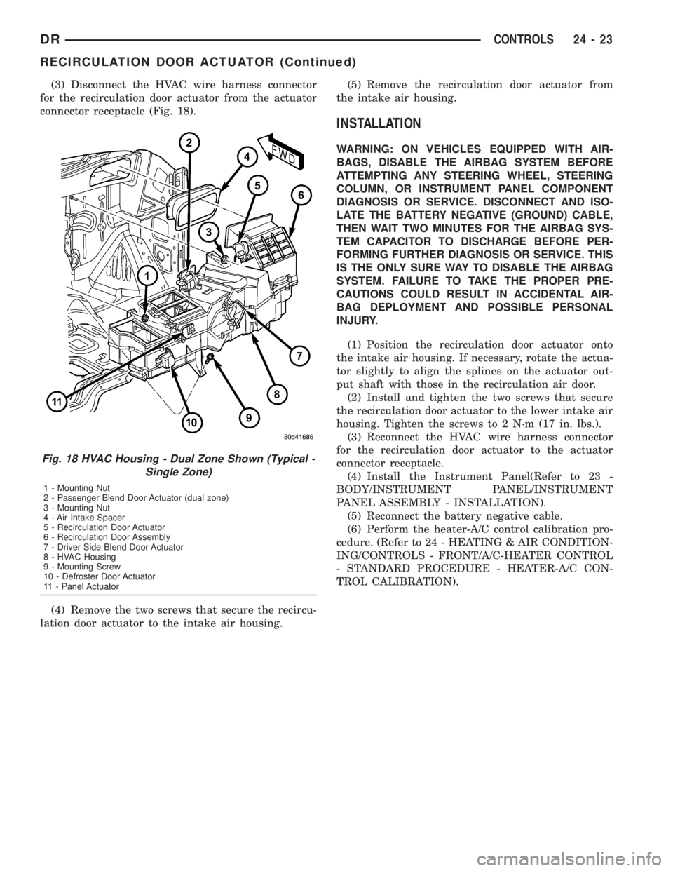
(3) Disconnect the HVAC wire harness connector
for the recirculation door actuator from the actuator
connector receptacle (Fig. 18).
(4) Remove the two screws that secure the recircu-
lation door actuator to the intake air housing.(5) Remove the recirculation door actuator from
the intake air housing.
INSTALLATION
WARNING: ON VEHICLES EQUIPPED WITH AIR-
BAGS, DISABLE THE AIRBAG SYSTEM BEFORE
ATTEMPTING ANY STEERING WHEEL, STEERING
COLUMN, OR INSTRUMENT PANEL COMPONENT
DIAGNOSIS OR SERVICE. DISCONNECT AND ISO-
LATE THE BATTERY NEGATIVE (GROUND) CABLE,
THEN WAIT TWO MINUTES FOR THE AIRBAG SYS-
TEM CAPACITOR TO DISCHARGE BEFORE PER-
FORMING FURTHER DIAGNOSIS OR SERVICE. THIS
IS THE ONLY SURE WAY TO DISABLE THE AIRBAG
SYSTEM. FAILURE TO TAKE THE PROPER PRE-
CAUTIONS COULD RESULT IN ACCIDENTAL AIR-
BAG DEPLOYMENT AND POSSIBLE PERSONAL
INJURY.
(1) Position the recirculation door actuator onto
the intake air housing. If necessary, rotate the actua-
tor slightly to align the splines on the actuator out-
put shaft with those in the recirculation air door.
(2) Install and tighten the two screws that secure
the recirculation door actuator to the lower intake air
housing. Tighten the screws to 2 N´m (17 in. lbs.).
(3) Reconnect the HVAC wire harness connector
for the recirculation door actuator to the actuator
connector receptacle.
(4) Install the Instrument Panel(Refer to 23 -
BODY/INSTRUMENT PANEL/INSTRUMENT
PANEL ASSEMBLY - INSTALLATION).
(5) Reconnect the battery negative cable.
(6) Perform the heater-A/C control calibration pro-
cedure. (Refer to 24 - HEATING & AIR CONDITION-
ING/CONTROLS - FRONT/A/C-HEATER CONTROL
- STANDARD PROCEDURE - HEATER-A/C CON-
TROL CALIBRATION).
Fig. 18 HVAC Housing - Dual Zone Shown (Typical -
Single Zone)
1 - Mounting Nut
2 - Passenger Blend Door Actuator (dual zone)
3 - Mounting Nut
4 - Air Intake Spacer
5 - Recirculation Door Actuator
6 - Recirculation Door Assembly
7 - Driver Side Blend Door Actuator
8 - HVAC Housing
9 - Mounting Screw
10 - Defroster Door Actuator
11 - Panel Actuator
DRCONTROLS 24 - 23
RECIRCULATION DOOR ACTUATOR (Continued)
Page 2799 of 2895
DISTRIBUTION
TABLE OF CONTENTS
page page
AIR OUTLETS
REMOVAL - PANEL OUTLETS.............24
INSTALLATION - PANEL OUTLETS..........24
BLEND DOOR
REMOVAL.............................24
INSTALLATION.........................25
BLOWER MOTOR
DESCRIPTION.........................25
OPERATION...........................25
DIAGNOSIS AND TESTING - BLOWER
MOTOR .............................26
REMOVAL.............................26
INSTALLATION.........................26
DEFROST DOOR
REMOVAL - DEFROST DOOR.............27
INSTALLATION - DEFROST DOOR..........27
FLOOR DISTRIBUTION DUCTS
REMOVAL.............................27INSTALLATION.........................27
HVAC HOUSING
REMOVAL.............................27
DISASSEMBLY.........................28
ASSEMBLY............................28
INSTALLATION.........................29
INSTRUMENT PANEL DUCTS
REMOVAL.............................29
INSTALLATION.........................29
MODE DOOR
REMOVAL - FLOOR - DEFROST DOOR......30
INSTALLATION - FLOOR - DEFROST DOOR . . 30
RECIRC DOOR
REMOVAL.............................30
INSTALLATION.........................30
AIR OUTLETS
REMOVAL - PANEL OUTLETS
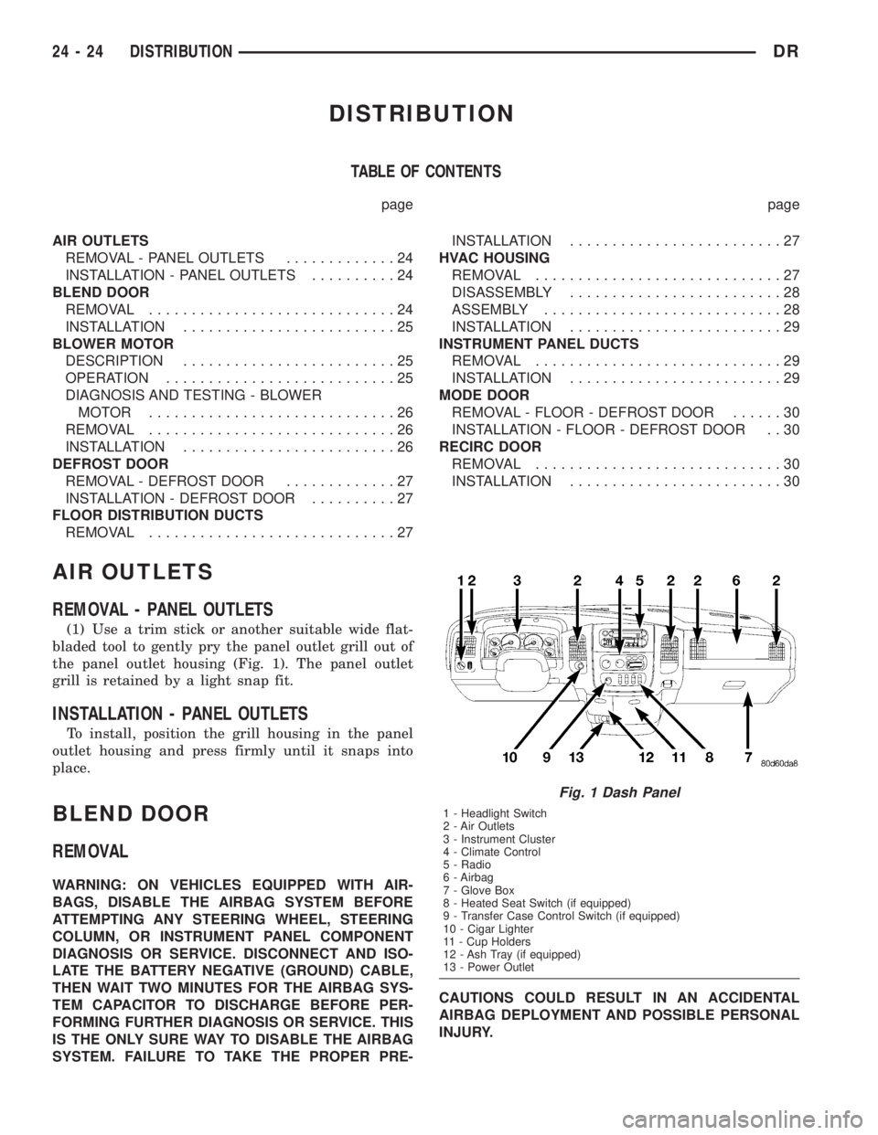
(1) Use a trim stick or another suitable wide flat-
bladed tool to gently pry the panel outlet grill out of
the panel outlet housing (Fig. 1). The panel outlet
grill is retained by a light snap fit.
INSTALLATION - PANEL OUTLETS
To install, position the grill housing in the panel
outlet housing and press firmly until it snaps into
place.
BLEND DOOR
REMOVAL
WARNING: ON VEHICLES EQUIPPED WITH AIR-
BAGS, DISABLE THE AIRBAG SYSTEM BEFORE
ATTEMPTING ANY STEERING WHEEL, STEERING
COLUMN, OR INSTRUMENT PANEL COMPONENT
DIAGNOSIS OR SERVICE. DISCONNECT AND ISO-
LATE THE BATTERY NEGATIVE (GROUND) CABLE,
THEN WAIT TWO MINUTES FOR THE AIRBAG SYS-
TEM CAPACITOR TO DISCHARGE BEFORE PER-
FORMING FURTHER DIAGNOSIS OR SERVICE. THIS
IS THE ONLY SURE WAY TO DISABLE THE AIRBAG
SYSTEM. FAILURE TO TAKE THE PROPER PRE-CAUTIONS COULD RESULT IN AN ACCIDENTAL
AIRBAG DEPLOYMENT AND POSSIBLE PERSONAL
INJURY.
Fig. 1 Dash Panel
1 - Headlight Switch
2 - Air Outlets
3 - Instrument Cluster
4 - Climate Control
5 - Radio
6 - Airbag
7 - Glove Box
8 - Heated Seat Switch (if equipped)
9 - Transfer Case Control Switch (if equipped)
10 - Cigar Lighter
11 - Cup Holders
12 - Ash Tray (if equipped)
13 - Power Outlet
24 - 24 DISTRIBUTIONDR
Page 2800 of 2895
(1) Recover refrigerant(Refer to 24 - HEATING &
AIR CONDITIONING/PLUMBING - STANDARD
PROCEDURE).
(2) Remove and disassemble the HVAC housing.
(Refer to 24 - HEATING & AIR CONDITIONING/
DISTRIBUTION/HVAC HOUSING - REMOVAL)
(Refer to 24 - HEATING & AIR CONDITIONING/
DISTRIBUTION/HVAC HOUSING - DISASSEMBLY)
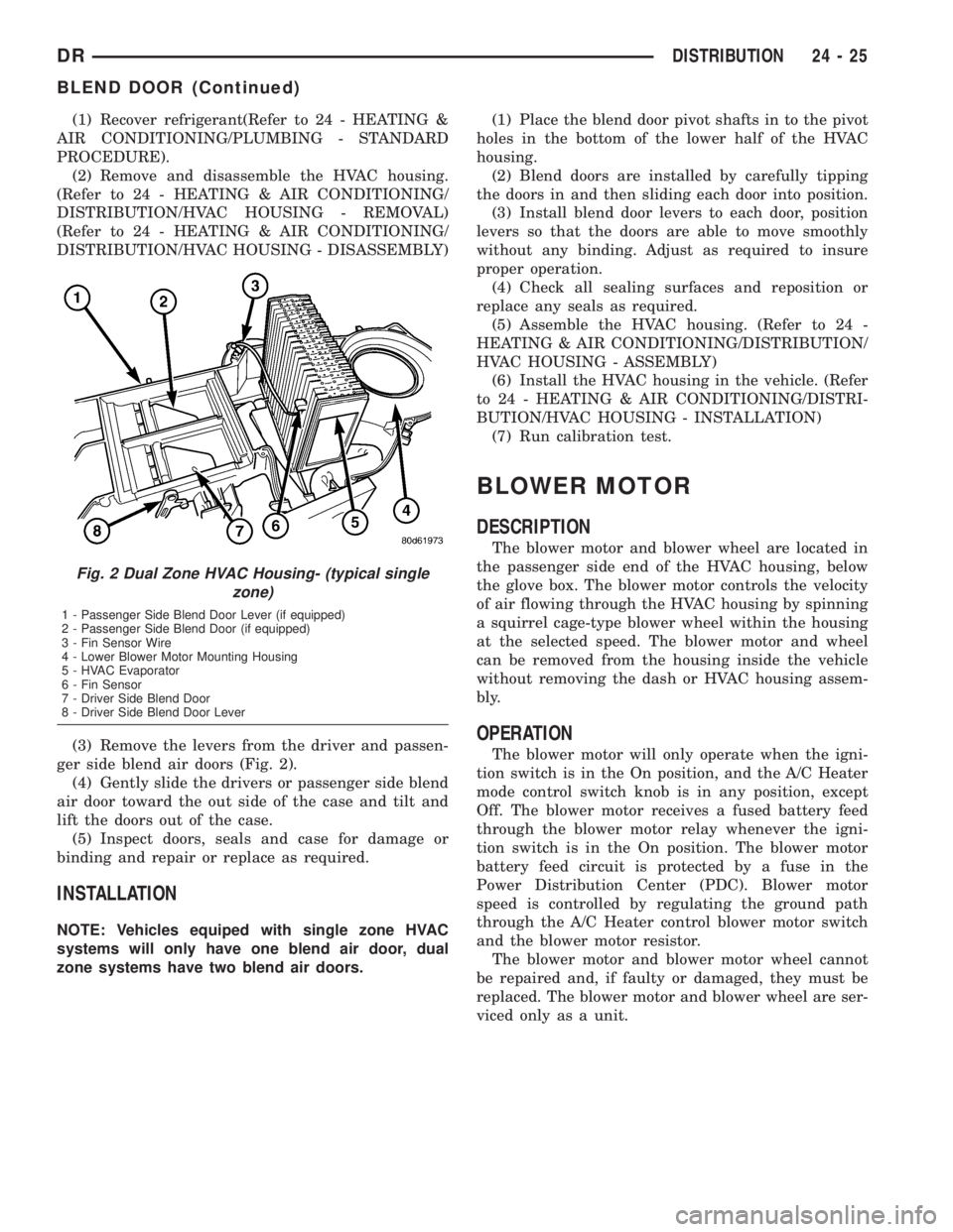
(3) Remove the levers from the driver and passen-
ger side blend air doors (Fig. 2).
(4) Gently slide the drivers or passenger side blend
air door toward the out side of the case and tilt and
lift the doors out of the case.
(5) Inspect doors, seals and case for damage or
binding and repair or replace as required.
INSTALLATION
NOTE: Vehicles equiped with single zone HVAC
systems will only have one blend air door, dual
zone systems have two blend air doors.(1) Place the blend door pivot shafts in to the pivot
holes in the bottom of the lower half of the HVAC
housing.
(2) Blend doors are installed by carefully tipping
the doors in and then sliding each door into position.
(3) Install blend door levers to each door, position
levers so that the doors are able to move smoothly
without any binding. Adjust as required to insure
proper operation.
(4) Check all sealing surfaces and reposition or
replace any seals as required.
(5) Assemble the HVAC housing. (Refer to 24 -
HEATING & AIR CONDITIONING/DISTRIBUTION/
HVAC HOUSING - ASSEMBLY)
(6) Install the HVAC housing in the vehicle. (Refer
to 24 - HEATING & AIR CONDITIONING/DISTRI-
BUTION/HVAC HOUSING - INSTALLATION)
(7) Run calibration test.
BLOWER MOTOR
DESCRIPTION
The blower motor and blower wheel are located in
the passenger side end of the HVAC housing, below
the glove box. The blower motor controls the velocity
of air flowing through the HVAC housing by spinning
a squirrel cage-type blower wheel within the housing
at the selected speed. The blower motor and wheel
can be removed from the housing inside the vehicle
without removing the dash or HVAC housing assem-
bly.
OPERATION
The blower motor will only operate when the igni-
tion switch is in the On position, and the A/C Heater
mode control switch knob is in any position, except
Off. The blower motor receives a fused battery feed
through the blower motor relay whenever the igni-
tion switch is in the On position. The blower motor
battery feed circuit is protected by a fuse in the
Power Distribution Center (PDC). Blower motor
speed is controlled by regulating the ground path
through the A/C Heater control blower motor switch
and the blower motor resistor.
The blower motor and blower motor wheel cannot
be repaired and, if faulty or damaged, they must be
replaced. The blower motor and blower wheel are ser-
viced only as a unit.
Fig. 2 Dual Zone HVAC Housing- (typical single
zone)
1 - Passenger Side Blend Door Lever (if equipped)
2 - Passenger Side Blend Door (if equipped)
3 - Fin Sensor Wire
4 - Lower Blower Motor Mounting Housing
5 - HVAC Evaporator
6 - Fin Sensor
7 - Driver Side Blend Door
8 - Driver Side Blend Door Lever
DRDISTRIBUTION 24 - 25
BLEND DOOR (Continued)
Page 2803 of 2895
(3) Recover the refrigerant from the refrigerant
system. (Refer to 24 - HEATING & AIR CONDI-
TIONING/PLUMBING - STANDARD PROCEDURE -
REFRIGERANT RECOVERY)
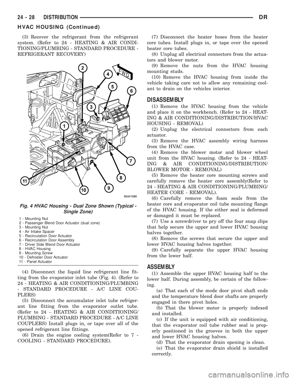
(4) Disconnect the liquid line refrigerant line fit-
ting from the evaporator inlet tube (Fig. 4). (Refer to
24 - HEATING & AIR CONDITIONING/PLUMBING
- STANDARD PROCEDURE - A/C LINE COU-
PLERS)
(5) Disconnect the accumulator inlet tube refriger-
ant line fitting from the evaporator outlet tube.
(Refer to 24 - HEATING & AIR CONDITIONING/
PLUMBING - STANDARD PROCEDURE - A/C LINE
COUPLERS) Install plugs in, or tape over all of the
opened refrigerant line fittings.
(6) Drain the engine cooling system(Refer to 7 -
COOLING - STANDARD PROCEDURE).(7) Disconnect the heater hoses from the heater
core tubes. Install plugs in, or tape over the opened
heater core tubes.
(8) Unplug all electrical connectors from the actua-
tors and blower motor.
(9) Remove the nuts from the HVAC housing
mounting studs.
(10) Remove the HVAC housing from inside the
vehicle taking care not to allow any remaining cool-
ant to drain on the vehicles interior.
DISASSEMBLY
(1) Remove the HVAC housing from the vehicle
and place it on the workbench. (Refer to 24 - HEAT-
ING & AIR CONDITIONING/DISTRIBUTION/HVAC
HOUSING - REMOVAL)
(2) Unplug the electrical connectors from each
actuator.
(3) Remove the HVAC assembly wiring harness
from the HVAC case.
(4) Remove the blower motor and blower wheel
unit from the HVAC housing. (Refer to 24 - HEAT-
ING & AIR CONDITIONING/DISTRIBUTION/
BLOWER MOTOR - REMOVAL)
(5) Remove the heater core mounting screws and
carefully remove the heater core assembly(Refer to
24 - HEATING & AIR CONDITIONING/PLUMBING/
HEATER CORE - REMOVAL).
(6) Carefully remove the foam seals from the
heater core and evaporator coil tube mounting flange
of the HVAC housing. If the either seal is deformed
or damaged it must be replaced.
(7) Use a screwdriver to pry off the four snap clips
that help secure the upper and lower HVAC housing
halves together.
(8) Remove the screws that secure the upper and
lower HVAC housing halves together.
(9) Carefully separate the upper HVAC housing
from the lower half.
ASSEMBLY
(1) Assemble the upper HVAC housing half to the
lower half. During assembly, be certain of the follow-
ing.
(a) That each of the mode door pivot shaft ends
and the temperature blend door shafts are properly
engaged in there pivot holes.
(b) That the blower motor is properly indexed
and installed.
(c) If the unit is equipped with air conditioning,
that the evaporator coil tube rubber seal is prop-
erly positioned in the grooves in both the upper
and lower HVAC housing halves.
(d) That the evaporator drain opening is clean.
(e) That the evaporator drain shield is installed
correctly.
Fig. 4 HVAC Housing - Dual Zone Shown (Typical -
Single Zone)
1 - Mounting Nut
2 - Passenger Blend Door Actuator (dual zone)
3 - Mounting Nut
4 - Air Intake Spacer
5 - Recirculation Door Actuator
6 - Recirculation Door Assembly
7 - Driver Side Blend Door Actuator
8 - HVAC Housing
9 - Mounting Screw
10 - Defroster Door Actuator
11 - Panel Actuator
24 - 28 DISTRIBUTIONDR
HVAC HOUSING (Continued)
Page 2823 of 2895
(1) Insert the evaporator coil into the bottom of the
HVAC housing. Make sure that the evaporator drain
is clean and unrestricted and evaporator deflector
shield is also installed.
(2) Reassemble and reinstall the HVAC housing in
the vehicle. (Refer to 24 - HEATING & AIR CONDI-
TIONING/DISTRIBUTION/HVAC HOUSING -
ASSEMBLY) (Refer to 24 - HEATING & AIR CON-
DITIONING/DISTRIBUTION/HVAC HOUSING -
INSTALLATION)
NOTE: If the evaporator is replaced, add 60 millili-
ters (2 fluid ounces) of refrigerant oil to the refrig-
erant system.
A/C ORIFICE TUBE
DESCRIPTION
The fixed orifice tube is installed in the liquid line
between the outlet of the condenser and the inlet of
the evaporator. The fixed orifice tube is only serviced
as an integral part of the liquid line.
OPERATION
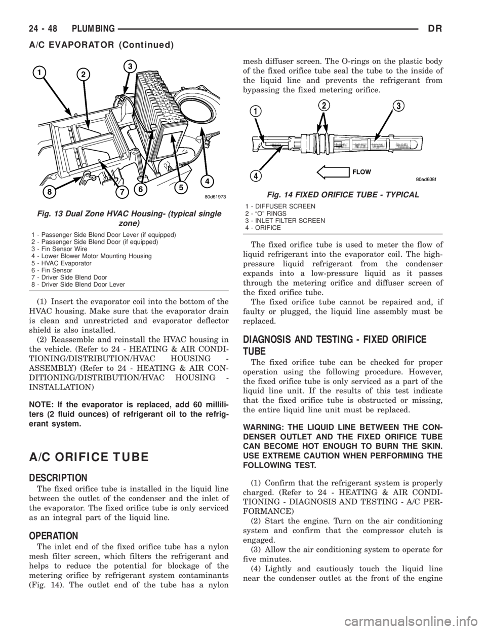
The inlet end of the fixed orifice tube has a nylon
mesh filter screen, which filters the refrigerant and
helps to reduce the potential for blockage of the
metering orifice by refrigerant system contaminants
(Fig. 14). The outlet end of the tube has a nylonmesh diffuser screen. The O-rings on the plastic body
of the fixed orifice tube seal the tube to the inside of
the liquid line and prevents the refrigerant from
bypassing the fixed metering orifice.
The fixed orifice tube is used to meter the flow of
liquid refrigerant into the evaporator coil. The high-
pressure liquid refrigerant from the condenser
expands into a low-pressure liquid as it passes
through the metering orifice and diffuser screen of
the fixed orifice tube.
The fixed orifice tube cannot be repaired and, if
faulty or plugged, the liquid line assembly must be
replaced.
DIAGNOSIS AND TESTING - FIXED ORIFICE
TUBE
The fixed orifice tube can be checked for proper
operation using the following procedure. However,
the fixed orifice tube is only serviced as a part of the
liquid line unit. If the results of this test indicate
that the fixed orifice tube is obstructed or missing,
the entire liquid line unit must be replaced.
WARNING: THE LIQUID LINE BETWEEN THE CON-
DENSER OUTLET AND THE FIXED ORIFICE TUBE
CAN BECOME HOT ENOUGH TO BURN THE SKIN.
USE EXTREME CAUTION WHEN PERFORMING THE
FOLLOWING TEST.
(1) Confirm that the refrigerant system is properly
charged. (Refer to 24 - HEATING & AIR CONDI-
TIONING - DIAGNOSIS AND TESTING - A/C PER-
FORMANCE)
(2) Start the engine. Turn on the air conditioning
system and confirm that the compressor clutch is
engaged.
(3) Allow the air conditioning system to operate for
five minutes.
(4) Lightly and cautiously touch the liquid line
near the condenser outlet at the front of the engine
Fig. 13 Dual Zone HVAC Housing- (typical single
zone)
1 - Passenger Side Blend Door Lever (if equipped)
2 - Passenger Side Blend Door (if equipped)
3 - Fin Sensor Wire
4 - Lower Blower Motor Mounting Housing
5 - HVAC Evaporator
6 - Fin Sensor
7 - Driver Side Blend Door
8 - Driver Side Blend Door Lever
Fig. 14 FIXED ORIFICE TUBE - TYPICAL
1 - DIFFUSER SCREEN
2 - ªOº RINGS
3 - INLET FILTER SCREEN
4 - ORIFICE
24 - 48 PLUMBINGDR
A/C EVAPORATOR (Continued)