2003 DODGE RAM ignition
[x] Cancel search: ignitionPage 1604 of 2895
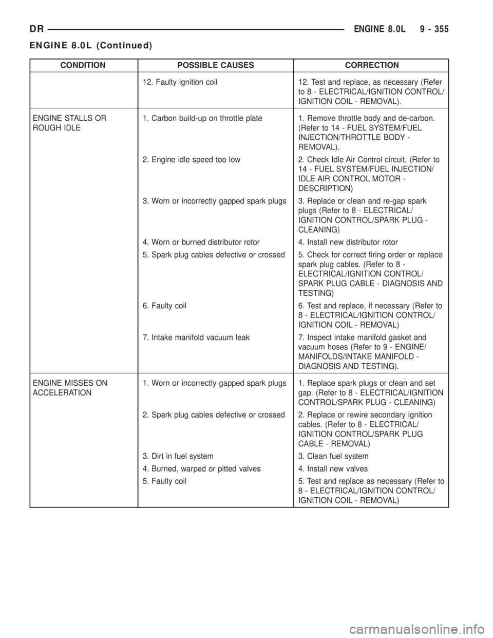
CONDITION POSSIBLE CAUSES CORRECTION
12. Faulty ignition coil 12. Test and replace, as necessary (Refer
to 8 - ELECTRICAL/IGNITION CONTROL/
IGNITION COIL - REMOVAL).
ENGINE STALLS OR
ROUGH IDLE1. Carbon build-up on throttle plate 1. Remove throttle body and de-carbon.
(Refer to 14 - FUEL SYSTEM/FUEL
INJECTION/THROTTLE BODY -
REMOVAL).
2. Engine idle speed too low 2. Check Idle Air Control circuit. (Refer to
14 - FUEL SYSTEM/FUEL INJECTION/
IDLE AIR CONTROL MOTOR -
DESCRIPTION)
3. Worn or incorrectly gapped spark plugs 3. Replace or clean and re-gap spark
plugs (Refer to 8 - ELECTRICAL/
IGNITION CONTROL/SPARK PLUG -
CLEANING)
4. Worn or burned distributor rotor 4. Install new distributor rotor
5. Spark plug cables defective or crossed 5. Check for correct firing order or replace
spark plug cables. (Refer to 8 -
ELECTRICAL/IGNITION CONTROL/
SPARK PLUG CABLE - DIAGNOSIS AND
TESTING)
6. Faulty coil 6. Test and replace, if necessary (Refer to
8 - ELECTRICAL/IGNITION CONTROL/
IGNITION COIL - REMOVAL)
7. Intake manifold vacuum leak 7. Inspect intake manifold gasket and
vacuum hoses (Refer to 9 - ENGINE/
MANIFOLDS/INTAKE MANIFOLD -
DIAGNOSIS AND TESTING).
ENGINE MISSES ON
ACCELERATION1. Worn or incorrectly gapped spark plugs 1. Replace spark plugs or clean and set
gap. (Refer to 8 - ELECTRICAL/IGNITION
CONTROL/SPARK PLUG - CLEANING)
2. Spark plug cables defective or crossed 2. Replace or rewire secondary ignition
cables. (Refer to 8 - ELECTRICAL/
IGNITION CONTROL/SPARK PLUG
CABLE - REMOVAL)
3. Dirt in fuel system 3. Clean fuel system
4. Burned, warped or pitted valves 4. Install new valves
5. Faulty coil 5. Test and replace as necessary (Refer to
8 - ELECTRICAL/IGNITION CONTROL/
IGNITION COIL - REMOVAL)
DRENGINE 8.0L 9 - 355
ENGINE 8.0L (Continued)
Page 1608 of 2895
DIAGNOSIS AND TESTINGÐCYLINDER
COMPRESSION PRESSURE
The results of a cylinder compression pressure test
can be utilized to diagnose several engine malfunc-
tions.
Ensure the battery is completely charged and the
engine starter motor is in good operating condition.
Otherwise, the indicated compression pressures may
not be valid for diagnosis purposes.
(1) Clean the spark plug recesses with compressed
air.
(2) Remove the spark plugs (Refer to 8 - ELEC-
TRICAL/IGNITION CONTROL/SPARK PLUG -
REMOVAL).
(3) Secure the throttle in the wide-open position.
(4) Disconnect the ignition coil.
(5) Insert a compression pressure gauge and rotate
the engine with the engine starter motor for three
revolutions.
(6) Record the compression pressure on the third
revolution. Continue the test for the remaining cylin-
ders.
(Refer to 9 - ENGINE - SPECIFICATIONS) for the
correct engine compression pressures.
DIAGNOSIS AND TESTING - CYLINDER
COMBUSTION PRESSURE LEAKAGE
The combustion pressure leakage test provides an
accurate means for determining engine condition.
Combustion pressure leakage testing will detect:
²Exhaust and intake valve leaks (improper seat-
ing)
²Leaks between adjacent cylinders or into water
jacket²Any causes for combustion/compression pressure
loss
WARNING: DO NOT REMOVE THE RADIATOR CAP
WITH THE SYSTEM HOT AND UNDER PRESSURE.
SERIOUS BURNS FROM HOT COOLANT CAN
OCCUR.
Check the coolant level and fill as required. DO
NOT install the radiator cap.
Start and operate the engine until it attains nor-
mal operating temperature, then turn OFF the
engine.
Remove the spark plugs.
Remove the oil filler cap.
Remove the air cleaner.
Calibrate the tester according to the manufactur-
er's instructions. The shop air source for testing
should maintain 483 kPa (70 psi) minimum, 1,379
kPa (200 psi) maximum and 552 kPa (80 psi) recom-
mended.
Perform the test procedure on each cylinder accord-
ing to the tester manufacturer's instructions. While
testing, listen for pressurized air escaping through
the throttle body, tailpipe or oil filler cap opening.
Check for bubbles in the radiator coolant.
All gauge pressure indications should be equal,
with no more than 25% leakage.
FOR EXAMPLE:At 552 kPa (80 psi) input pres-
sure, a minimum of 414 kPa (60 psi) should be main-
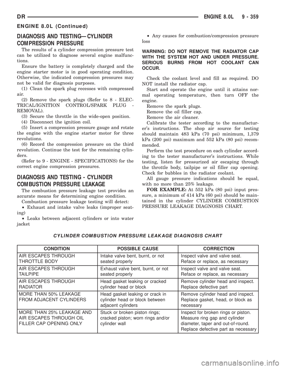
tained in the cylinder CYLINDER COMBUSTION
PRESSURE LEAKAGE DIAGNOSIS CHART.
CYLINDER COMBUSTION PRESSURE LEAKAGE DIAGNOSIS CHART
CONDITION POSSIBLE CAUSE CORRECTION
AIR ESCAPES THROUGH
THROTTLE BODYIntake valve bent, burnt, or not
seated properlyInspect valve and valve seat.
Reface or replace, as necessary
AIR ESCAPES THROUGH
TAILPIPEExhaust valve bent, burnt, or not
seated properlyInspect valve and valve seat.
Reface or replace, as necessary
AIR ESCAPES THROUGH
RADIATORHead gasket leaking or cracked
cylinder head or blockRemove cylinder head and inspect.
Replace defective part
MORE THAN 50% LEAKAGE
FROM ADJACENT CYLINDERSHead gasket leaking or crack in
cylinder head or block between
adjacent cylindersRemove cylinder head and inspect.
Replace gasket, head, or block as
necessary
MORE THAN 25% LEAKAGE AND
AIR ESCAPES THROUGH OIL
FILLER CAP OPENING ONLYStuck or broken piston rings;
cracked piston; worn rings and/or
cylinder wallInspect for broken rings or piston.
Measure ring gap and cylinder
diameter, taper and out-of-round.
Replace defective part as necessary
DRENGINE 8.0L 9 - 359
ENGINE 8.0L (Continued)
Page 1611 of 2895
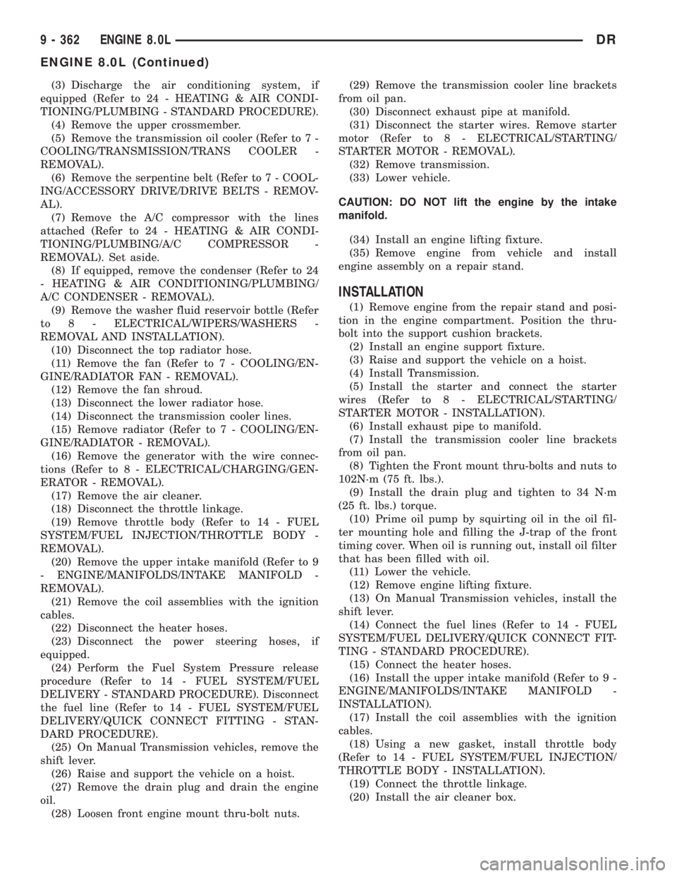
(3) Discharge the air conditioning system, if
equipped (Refer to 24 - HEATING & AIR CONDI-
TIONING/PLUMBING - STANDARD PROCEDURE).
(4) Remove the upper crossmember.
(5) Remove the transmission oil cooler (Refer to 7 -
COOLING/TRANSMISSION/TRANS COOLER -
REMOVAL).
(6) Remove the serpentine belt (Refer to 7 - COOL-
ING/ACCESSORY DRIVE/DRIVE BELTS - REMOV-
AL).
(7) Remove the A/C compressor with the lines
attached (Refer to 24 - HEATING & AIR CONDI-
TIONING/PLUMBING/A/C COMPRESSOR -
REMOVAL). Set aside.
(8) If equipped, remove the condenser (Refer to 24
- HEATING & AIR CONDITIONING/PLUMBING/
A/C CONDENSER - REMOVAL).
(9) Remove the washer fluid reservoir bottle (Refer
to 8 - ELECTRICAL/WIPERS/WASHERS -
REMOVAL AND INSTALLATION).
(10) Disconnect the top radiator hose.
(11) Remove the fan (Refer to 7 - COOLING/EN-
GINE/RADIATOR FAN - REMOVAL).
(12) Remove the fan shroud.
(13) Disconnect the lower radiator hose.
(14) Disconnect the transmission cooler lines.
(15) Remove radiator (Refer to 7 - COOLING/EN-
GINE/RADIATOR - REMOVAL).
(16) Remove the generator with the wire connec-
tions (Refer to 8 - ELECTRICAL/CHARGING/GEN-
ERATOR - REMOVAL).
(17) Remove the air cleaner.
(18) Disconnect the throttle linkage.
(19) Remove throttle body (Refer to 14 - FUEL
SYSTEM/FUEL INJECTION/THROTTLE BODY -
REMOVAL).
(20) Remove the upper intake manifold (Refer to 9
- ENGINE/MANIFOLDS/INTAKE MANIFOLD -
REMOVAL).
(21) Remove the coil assemblies with the ignition
cables.
(22) Disconnect the heater hoses.
(23) Disconnect the power steering hoses, if
equipped.
(24) Perform the Fuel System Pressure release
procedure (Refer to 14 - FUEL SYSTEM/FUEL
DELIVERY - STANDARD PROCEDURE). Disconnect
the fuel line (Refer to 14 - FUEL SYSTEM/FUEL
DELIVERY/QUICK CONNECT FITTING - STAN-
DARD PROCEDURE).
(25) On Manual Transmission vehicles, remove the
shift lever.
(26) Raise and support the vehicle on a hoist.
(27) Remove the drain plug and drain the engine
oil.
(28) Loosen front engine mount thru-bolt nuts.(29) Remove the transmission cooler line brackets
from oil pan.
(30) Disconnect exhaust pipe at manifold.
(31) Disconnect the starter wires. Remove starter
motor (Refer to 8 - ELECTRICAL/STARTING/
STARTER MOTOR - REMOVAL).
(32) Remove transmission.
(33) Lower vehicle.
CAUTION: DO NOT lift the engine by the intake
manifold.
(34) Install an engine lifting fixture.
(35) Remove engine from vehicle and install
engine assembly on a repair stand.
INSTALLATION
(1) Remove engine from the repair stand and posi-
tion in the engine compartment. Position the thru-
bolt into the support cushion brackets.
(2) Install an engine support fixture.
(3) Raise and support the vehicle on a hoist.
(4) Install Transmission.
(5) Install the starter and connect the starter
wires (Refer to 8 - ELECTRICAL/STARTING/
STARTER MOTOR - INSTALLATION).
(6) Install exhaust pipe to manifold.
(7) Install the transmission cooler line brackets
from oil pan.
(8) Tighten the Front mount thru-bolts and nuts to
102N´m (75 ft. lbs.).
(9) Install the drain plug and tighten to 34 N´m
(25 ft. lbs.) torque.
(10) Prime oil pump by squirting oil in the oil fil-
ter mounting hole and filling the J-trap of the front
timing cover. When oil is running out, install oil filter
that has been filled with oil.
(11) Lower the vehicle.
(12) Remove engine lifting fixture.
(13) On Manual Transmission vehicles, install the
shift lever.
(14) Connect the fuel lines (Refer to 14 - FUEL
SYSTEM/FUEL DELIVERY/QUICK CONNECT FIT-
TING - STANDARD PROCEDURE).
(15) Connect the heater hoses.
(16) Install the upper intake manifold (Refer to 9 -
ENGINE/MANIFOLDS/INTAKE MANIFOLD -
INSTALLATION).
(17) Install the coil assemblies with the ignition
cables.
(18) Using a new gasket, install throttle body
(Refer to 14 - FUEL SYSTEM/FUEL INJECTION/
THROTTLE BODY - INSTALLATION).
(19) Connect the throttle linkage.
(20) Install the air cleaner box.
9 - 362 ENGINE 8.0LDR
ENGINE 8.0L (Continued)
Page 1622 of 2895
(4) Install push rods and rocker arm assemblies in
their original position (Refer to 9 - ENGINE/CYLIN-
DER HEAD/ROCKER ARM / ADJUSTER ASSY -
INSTALLATION).
(5) Install lower intake manifold (Refer to 9 -
ENGINE/MANIFOLDS/INTAKE MANIFOLD -
INSTALLATION).
(6) Install the upper intake manifold onto the
lower intake manifold (Refer to 9 - ENGINE/MANI-
FOLDS/INTAKE MANIFOLD - INSTALLATION).
(7) Install the exhaust manifolds and new gaskets
(Refer to 9 - ENGINE/MANIFOLDS/EXHAUST
MANIFOLD - INSTALLATION).
(8) Install exhaust pipe to the exhaust manifold.
Tighten the bolts to 34 n´m (25 ft. lbs.) torque.
(9) Using a new gasket, position the EGR tube to
the intake manifold and the exhaust manifold.
Tighten the EGR tube nut to 34 N´m (25 ft. lbs.)
torque. Tighten the bolts to 20 N´m (174 in. lbs.)
torque.
(10) Install the heat shields and the washers.
Make sure that heat shields tabs hook over the
exhaust gasket.Tighten the nuts to 15 N´m (132 in.
lbs.) torque.
(11) Adjust and Install the spark plugs (Refer to 8
- ELECTRICAL/IGNITION CONTROL/SPARK
PLUG - INSTALLATION).
(12) Install coil packs and bracket. Tighten the
bracket bolts to 21 N´m (190 in. lbs.) torque. Connect
the coil wires.
(13) Connect heat indicator sending unit wire.
(14) Connect the heater hoses and bypass hose.
(15) Connect the accelerator linkage and if so
equipped, the speed control and transmission kick-
down cables.
(16) Install the fuel line (Refer to 14 - FUEL SYS-
TEM/FUEL DELIVERY/QUICK CONNECT FIT-
TING - STANDARD PROCEDURE).
(17) Install the generator (Refer to 8 - ELECTRI-
CAL/CHARGING/GENERATOR - INSTALLATION)
and drive belt (Refer to 7 - COOLING/ACCESSORY
DRIVE/DRIVE BELTS - INSTALLATION).
(18) Install the intake manifold-to-generator
bracket support rod. Tighten the bolts to 41 N´m (30
ft. lbs.) torque.
(19) The cylinder head cover gasket can be used
again. Install the gasket onto the head rail.For the
left side the number tab is at the front of
engine with the number up. For the right side
the number tab is at the rear of engine with the
number up.
CAUTION: The cylinder head cover fasteners have a
special plating. DO NOT use alternative fasteners.(20) Install cylinder head cover (Refer to 9 -
ENGINE/CYLINDER HEAD/CYLINDER HEAD
COVER(S) - INSTALLATION).
(21) Install closed crankcase ventilation system.
(22) Connect the evaporation control system.
(23) Install the air cleaner.
(24) Fill cooling system (Refer to 7 - COOLING -
STANDARD PROCEDURE).
(25) Connect the negative cable to the battery.
(26) Check for leaks (fuel, oil, antifreeze, etc.).
CYLINDER HEAD COVER(S)
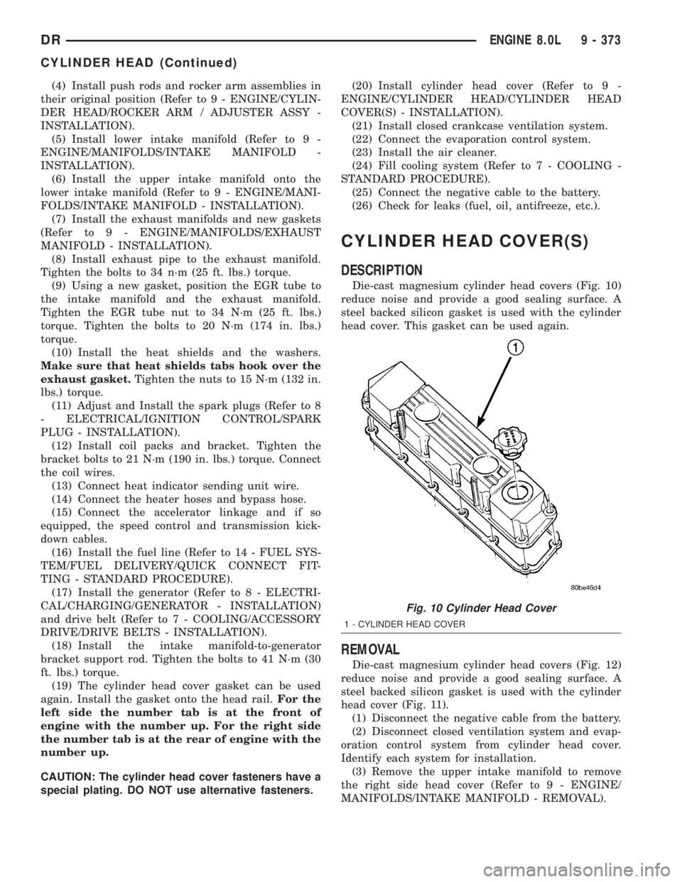
DESCRIPTION
Die-cast magnesium cylinder head covers (Fig. 10)
reduce noise and provide a good sealing surface. A
steel backed silicon gasket is used with the cylinder
head cover. This gasket can be used again.
REMOVAL
Die-cast magnesium cylinder head covers (Fig. 12)
reduce noise and provide a good sealing surface. A
steel backed silicon gasket is used with the cylinder
head cover (Fig. 11).
(1) Disconnect the negative cable from the battery.
(2) Disconnect closed ventilation system and evap-
oration control system from cylinder head cover.
Identify each system for installation.
(3) Remove the upper intake manifold to remove
the right side head cover (Refer to 9 - ENGINE/
MANIFOLDS/INTAKE MANIFOLD - REMOVAL).
Fig. 10 Cylinder Head Cover
1 - CYLINDER HEAD COVER
DRENGINE 8.0L 9 - 373
CYLINDER HEAD (Continued)
Page 1626 of 2895
REMOVAL
REMOVALÐVALVE STEM SEALS
NOTE: This procedure is done with the cylinder
head installed.
(1) Disconnect the negative cable from the battery.
(2) Set engine basic timing to Top Dead Center
(TDC) and remove air cleaner.
(3) Remove cylinder head covers (Refer to 9 -
ENGINE/CYLINDER HEAD/CYLINDER HEAD
COVER(S) - REMOVAL) and spark plugs (Refer to 8
- ELECTRICAL/IGNITION CONTROL/SPARK
PLUG - REMOVAL).
(4) Using suitable socket and flex handle at crank-
shaft retaining bolt, turn engine so that the piston of
the cylinder to be worked on, is at TDC on the com-
pression stroke.
(5) Remove rocker arms (Refer to 9 - ENGINE/
CYLINDER HEAD/ROCKER ARM / ADJUSTER
ASSY - REMOVAL).
(6) With air hose attached to an adapter installed
in the spark plug hole, apply 620-689 kPa (90-100
psi) air pressure.
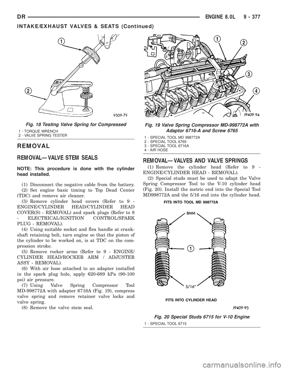
(7) Using Valve Spring Compressor Tool
MD-998772A with adapter 6716A (Fig. 19), compress
valve spring and remove retainer valve locks and
valve spring.
(8) Remove the valve stem seal.
REMOVALÐVALVES AND VALVE SPRINGS
(1) Remove the cylinder head (Refer to 9 -
ENGINE/CYLINDER HEAD - REMOVAL).
(2) Special studs must be used to adapt the Valve
Spring Compressor Tool to the V-10 cylinder head
(Fig. 20). Install the metric end into the Special Tool
MD998772A and the 5/16 end into the cylinder head.
Fig. 18 Testing Valve Spring for Compressed
1 - TORQUE WRENCH
2 - VALVE SPRING TESTER
Fig. 19 Valve Spring Compressor MD-998772A with
Adaptor 6716-A and Screw 6765
1 - SPECIAL TOOL MD 998772A
2 - SPECIAL TOOL 6765
3 - SPECIAL TOOL 6716A
4 - AIR HOSE
Fig. 20 Special Studs 6715 for V-10 Engine
1 - SPECIAL TOOL 6715
DRENGINE 8.0L 9 - 377
INTAKE/EXHAUST VALVES & SEATS (Continued)
Page 1650 of 2895
(7) Using a new pressure relief valve gasket,
install the relief valve plug. Tighten the plug to 20
N´m (15 ft. lbs.) torque.
(8) Install oil filter that has been filled with oil.
INTAKE MANIFOLD
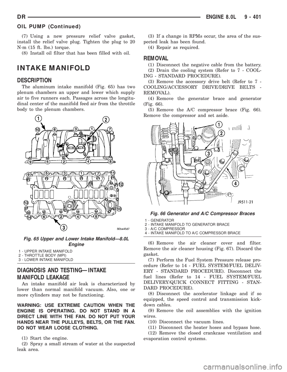
DESCRIPTION
The aluminum intake manifold (Fig. 65) has two
plenum chambers an upper and lower which supply
air to five runners each. Passages across the longitu-
dinal center of the manifold feed air from the throttle
body to the plenum chambers.
DIAGNOSIS AND TESTINGÐINTAKE
MANIFOLD LEAKAGE
An intake manifold air leak is characterized by
lower than normal manifold vacuum. Also, one or
more cylinders may not be functioning.
WARNING: USE EXTREME CAUTION WHEN THE
ENGINE IS OPERATING. DO NOT STAND IN A
DIRECT LINE WITH THE FAN. DO NOT PUT YOUR
HANDS NEAR THE PULLEYS, BELTS, OR THE FAN.
DO NOT WEAR LOOSE CLOTHING.
(1) Start the engine.
(2) Spray a small stream of water at the suspected
leak area.(3) If a change in RPMs occur, the area of the sus-
pected leak has been found.
(4) Repair as required.
REMOVAL
(1) Disconnect the negative cable from the battery.
(2) Drain the cooling system (Refer to 7 - COOL-
ING - STANDARD PROCEDURE).
(3) Remove the accessory drive belt (Refer to 7 -
COOLING/ACCESSORY DRIVE/DRIVE BELTS -
REMOVAL).
(4) Remove the generator brace and generator
(Fig. 66).
(5) Remove the A/C compressor brace (Fig. 66).
Remove the compressor and set aside.
(6) Remove the air cleaner cover and filter.
Remove the air cleaner housing (Fig. 67). Discard the
gasket.
(7) Perform the Fuel System Pressure release pro-
cedure (Refer to 14 - FUEL SYSTEM/FUEL DELIV-
ERY - STANDARD PROCEDURE). Disconnect the
fuel lines (Refer to 14 - FUEL SYSTEM/FUEL
DELIVERY/QUICK CONNECT FITTING - STAN-
DARD PROCEDURE).
(8) Disconnect the accelerator linkage and if so
equipped, the speed control and transmission kick-
down cables.
(9) Remove the coil assemblies with the ignition
wires.
(10) Disconnect the vacuum lines.
(11) Disconnect the heater hoses and bypass hose.
(12) Remove the closed crankcase ventilation and
evaporation control systems.
Fig. 65 Upper and Lower Intake ManifoldÐ8.0L
Engine
1 - UPPER INTAKE MANIFOLD
2 - THROTTLE BODY (MPI)
3 - LOWER INTAKE MANIFOLD
Fig. 66 Generator and A/C Compressor Braces
1 - GENERATOR
2 - INTAKE MANIFOLD TO GENERATOR BRACE
3 - A/C COMPRESSOR
4 - INTAKE MANIFOLD TO A/C COMPRESSOR BRACE
DRENGINE 8.0L 9 - 401
OIL PUMP (Continued)
Page 1652 of 2895

(2) Insert MopartGEN II Silicone Rubber Adhe-
sive Sealant, or equivalent, into the four corner joints
an excessive amount of sealant is not required to
ensure a leak proof seal. However, an excessive
amount of sealant may reduce the effectiveness of
the flange gasket. The sealant should be approxi-
mately 5 mm (0.2 in.) in diameter. (Fig. 70).
(3) Position the cross-over gaskets and press firmly
onto the block (Fig. 70).BE SURE THE BLOCK IS
OIL FREE..
(4) The lower intake manifold MUST be installed
within 3 minutes of sealant application. Carefully
lower intake manifold into position on the cylinder
block and heads. After intake manifold is in place,
inspect to make sure seals and gaskets are in place.
Finger start all the lower intake bolts.
(5) Tighten the lower intake manifold bolts in
sequence to 54 N´m (40 ft. lbs.) torque (Fig. 69).
Recheck all bolts are tightened to 54 N´m (40 ft. lbs.)
torque.
(6) Using a new gasket, position the upper intake
manifold onto the lower intake manifold.
(7) Finger start all bolts, alternate one side to the
other.
(8) Tighten upper intake manifold bolts in
sequence to 22 N´m (16 ft. lbs.) torque (Fig. 68).
(9) Using a new gasket, install the throttle body
onto the upper intake manifold. Tighten the bolts to
23 N´m (200 in. lbs.) torque.
(10) Install closed crankcase ventilation and evap-
oration control systems.
(11) Connect the heater hoses and bypass hose.
(12) Connect the vacuum lines.
(13) Install the coil assemblies and the ignition
wires.
(14) Connect the accelerator linkage and if so
equipped, the speed control and transmission kick-
down cables.(15) Install the fuel lines (Refer to 14 - FUEL SYS-
TEM/FUEL DELIVERY/QUICK CONNECT FIT-
TING - STANDARD PROCEDURE).
(16) Using a new gasket, install the air cleaner
housing. Tighten the nuts to 11 N´m (96 in. lbs.)
torque. Install the air cleaner filter and cover.
(17) Install the A/C compressor (Refer to 24 -
HEATING & AIR CONDITIONING/PLUMBING/A/C
COMPRESSOR - INSTALLATION). Position the com-
pressor brace and install the bolts. Tighten the brace
bolts to 41 N´m (30 ft. lbs.) torque.
(18) Install the generator (Refer to 8 - ELECTRI-
CAL/CHARGING/GENERATOR - INSTALLATION).
Position the generator brace and install the bolts.
Tighten the brace bolts to 41 N´m (30 ft. lbs.) torque.
(19) Install the accessory drive belt (Refer to 7 -
COOLING/ACCESSORY DRIVE/DRIVE BELTS -
INSTALLATION).
(20) Fill cooling system (Refer to 7 - COOLING -
STANDARD PROCEDURE).
(21) Connect the negative cable to the battery.
(22) Start engine check for leaks.
EXHAUST MANIFOLD
DESCRIPTION
Engine exhaust manifolds (Fig. 72) are made of
high molybdenum ductile cast iron. A special ribbed
design helps control permanent dimensional changes
during heat cycles.
OPERATION
The exhaust manifolds collect the engine exhaust
exiting the combustion chambers, then channels the
exhaust gases to the exhaust pipes attached to the
manifolds.
Fig. 71 Intake Manifold Flange
1 - LOCATOR DOWELS
2 - INTAKE MANIFOLD GASKETS
3 - LOCATOR DOWELS
Fig. 72 Exhaust ManifoldÐ8.0L Engine
1 - EXHAUST MANIFOLD
DRENGINE 8.0L 9 - 403
INTAKE MANIFOLD (Continued)
Page 1700 of 2895
(2) Remove fuel pump relay from Power Distribu-
tion Center (PDC). For location of relay, refer to label
on underside of PDC cover.
(3) Start and run engine until it stalls.
(4) Attempt restarting engine until it will no
longer run.
(5) Turn ignition key to OFF position.
CAUTION: Steps 1, 2, 3 and 4 must be performed to
relieve high pressure fuel from within fuel rail. Do
not attempt to use following steps to relieve this
pressure as excessive fuel will be forced into a cyl-
inder chamber.
(6) Unplug connector from any fuel injector.
(7) Attach one end of a jumper wire with alligator
clips (18 gauge or smaller) to either injector terminal.
(8) Connect other end of jumper wire to positive
side of battery.(9) Connect one end of a second jumper wire to
remaining injector terminal.
CAUTION: Powering an injector for more than a few
seconds will permanently damage the injector.
(10) Momentarily touch other end of jumper wire
to negative terminal of battery for no more than a
few seconds.
(11) Place a rag or towel below fuel line quick-con-
nect fitting at fuel rail.
(12) Disconnect quick-connect fitting at fuel rail.
Refer to Quick-Connect Fittings.
(13) Return fuel pump relay to PDC.
(14) One or more Diagnostic Trouble Codes (DTC's)
may have been stored in PCM memory due to fuel
pump relay removal. The DRBtscan tool must be
used to erase a DTC.
SPECIFICATIONS
FUEL SYSTEM PRESSURE
339 kPa +/- 34 kPa (49.2 psi +/- 2 psi).
TORQUE - FUEL SYSTEM
DESCRIPTION N-m Ft. Lbs. In. Lbs.
Accelerator Pedal Bracket
Mounting12 - 105
Accelerator Pedal Position
Sensor Bracket-to-Battery
Tray Bolts3-30
Crankshaft Position
Sensor - 3.7L28 21 -
Crankshaft Position
Sensor - 4.7L28 21 -
Crankshaft Position
Sensor - 5.7L12 - 105 (+/-20)
Crankshaft Position
Sensor - 5.9L8-70
Crankshaft Position
Sensor - 8.0L8-70
Camshaft Position Sensor
- 3.7L12 - 106
Camshaft Position Sensor
- 4.7L12 - 106
Camshaft Position Sensor
- 5.7L12 9 105 (+/-) 20
Camshaft Position Sensor
- 8.0L6-50
DRFUEL DELIVERY - GAS 14 - 3
FUEL DELIVERY - GAS (Continued)