2003 DODGE RAM ignition
[x] Cancel search: ignitionPage 1806 of 2895
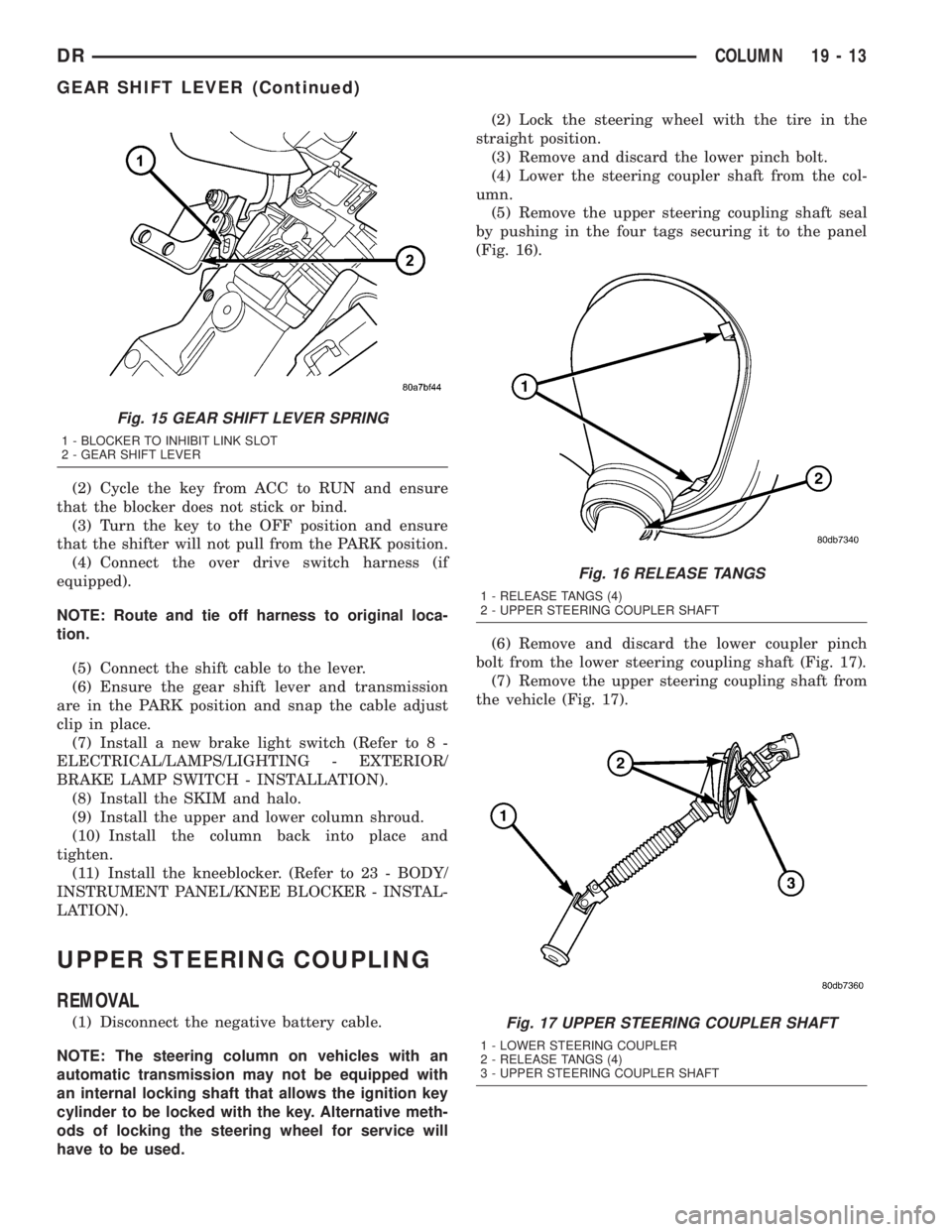
(2) Cycle the key from ACC to RUN and ensure
that the blocker does not stick or bind.
(3) Turn the key to the OFF position and ensure
that the shifter will not pull from the PARK position.
(4) Connect the over drive switch harness (if
equipped).
NOTE: Route and tie off harness to original loca-
tion.
(5) Connect the shift cable to the lever.
(6) Ensure the gear shift lever and transmission
are in the PARK position and snap the cable adjust
clip in place.
(7) Install a new brake light switch (Refer to 8 -
ELECTRICAL/LAMPS/LIGHTING - EXTERIOR/
BRAKE LAMP SWITCH - INSTALLATION).
(8) Install the SKIM and halo.
(9) Install the upper and lower column shroud.
(10) Install the column back into place and
tighten.
(11) Install the kneeblocker. (Refer to 23 - BODY/
INSTRUMENT PANEL/KNEE BLOCKER - INSTAL-
LATION).
UPPER STEERING COUPLING
REMOVAL
(1) Disconnect the negative battery cable.
NOTE: The steering column on vehicles with an
automatic transmission may not be equipped with
an internal locking shaft that allows the ignition key
cylinder to be locked with the key. Alternative meth-
ods of locking the steering wheel for service will
have to be used.(2) Lock the steering wheel with the tire in the
straight position.
(3) Remove and discard the lower pinch bolt.
(4) Lower the steering coupler shaft from the col-
umn.
(5) Remove the upper steering coupling shaft seal
by pushing in the four tags securing it to the panel
(Fig. 16).
(6) Remove and discard the lower coupler pinch
bolt from the lower steering coupling shaft (Fig. 17).
(7) Remove the upper steering coupling shaft from
the vehicle (Fig. 17).
Fig. 15 GEAR SHIFT LEVER SPRING
1 - BLOCKER TO INHIBIT LINK SLOT
2 - GEAR SHIFT LEVER
Fig. 16 RELEASE TANGS
1 - RELEASE TANGS (4)
2 - UPPER STEERING COUPLER SHAFT
Fig. 17 UPPER STEERING COUPLER SHAFT
1 - LOWER STEERING COUPLER
2 - RELEASE TANGS (4)
3 - UPPER STEERING COUPLER SHAFT
DRCOLUMN 19 - 13
GEAR SHIFT LEVER (Continued)
Page 1807 of 2895
INSTALLATION
(1) Install the upper steering coupling shaft to the
vehicle (Fig. 17).
(2) Install the upper steering coupling shaft seal
by pushing it in securing the four tangs to the panel
(Fig. 16).
NOTE: Note: A new steering coupling shaft pinch
bolt for the upper and lower shafts must be used.
(3) Install the steering coupler shaft to the column
(Fig. 17).
(4) Install the upper pinch bolt use new bolt and
tighten to 57 N.m (42 ft.lbs).
(5) Install the shaft to the lower coupler (Fig. 17).
(6) Install the lower pinch bolt use new bolt and
tighten to 57 N.m (42 ft.lbs).
(7) Unlock the steering wheel.
(8) Reconnect the negative battery cable.
LOWER STEERING COUPLING
REMOVAL
REMOVAL - ALL LD & HD EXCEPT 4X4 HD
(1) Disconnect the negative battery cable.
(2) Raise and support the vehicle.
NOTE: The steering column on vehicles with an
automatic transmission may not be equipped with
an internal locking shaft that allows the ignition key
cylinder to be locked with the key. Alternative meth-
ods of locking the steering wheel for service will
have to be used.
(3) Lock the steering wheel with the tire in the
straight position.
(4) Remove the left front tire and wheel assembly.
(5) Mark both coupler connections for proper
installation.
(6) Remove and discard the upper coupler pinch
bolt.
(7) Remove and discard the lower coupler pinch
bolt.
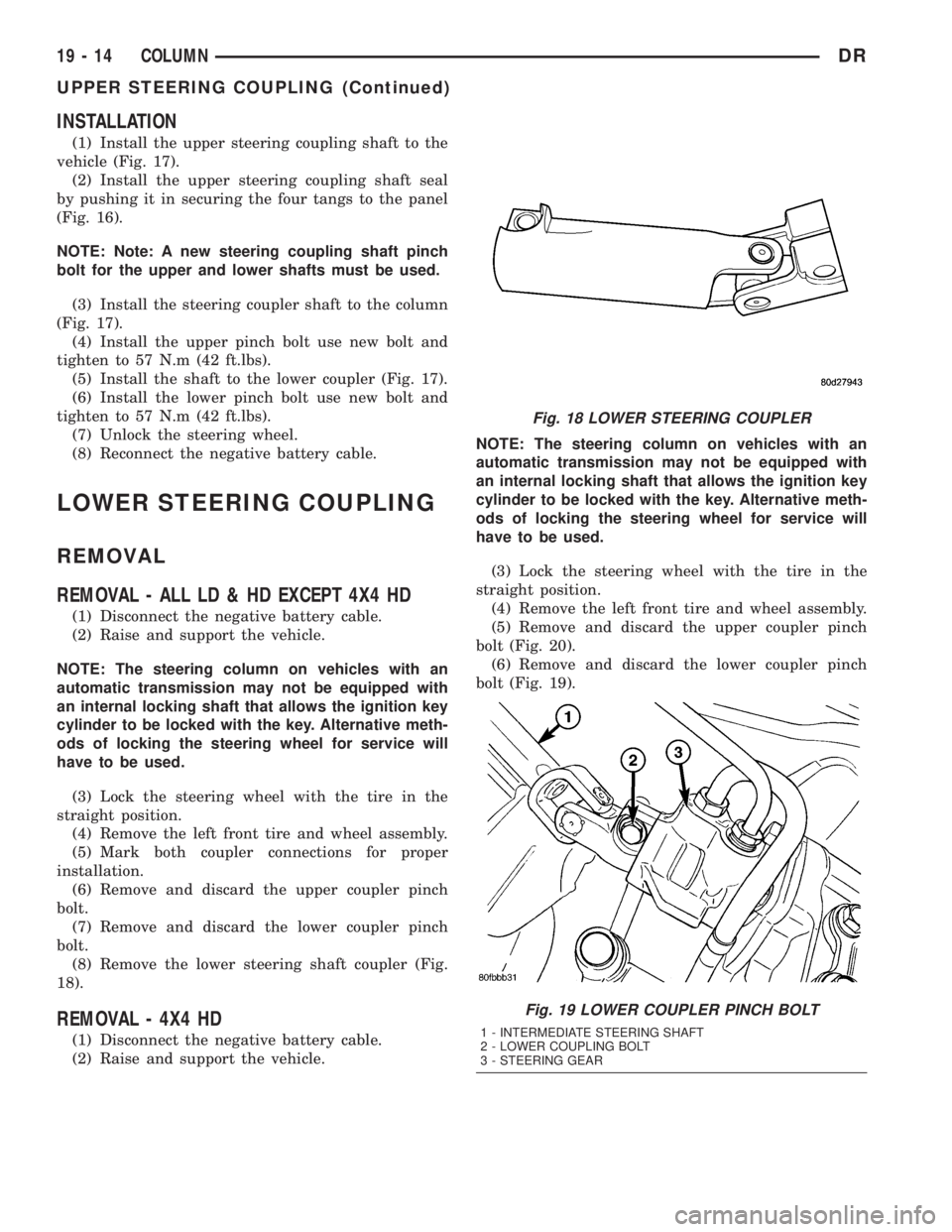
(8) Remove the lower steering shaft coupler (Fig.
18).
REMOVAL - 4X4 HD
(1) Disconnect the negative battery cable.
(2) Raise and support the vehicle.NOTE: The steering column on vehicles with an
automatic transmission may not be equipped with
an internal locking shaft that allows the ignition key
cylinder to be locked with the key. Alternative meth-
ods of locking the steering wheel for service will
have to be used.
(3) Lock the steering wheel with the tire in the
straight position.
(4) Remove the left front tire and wheel assembly.
(5) Remove and discard the upper coupler pinch
bolt (Fig. 20).
(6) Remove and discard the lower coupler pinch
bolt (Fig. 19).
Fig. 18 LOWER STEERING COUPLER
Fig. 19 LOWER COUPLER PINCH BOLT
1 - INTERMEDIATE STEERING SHAFT
2 - LOWER COUPLING BOLT
3 - STEERING GEAR
19 - 14 COLUMNDR
UPPER STEERING COUPLING (Continued)
Page 1809 of 2895
GEAR - INDEPENDENT FRONT SUSPENSION
TABLE OF CONTENTS
page page
GEAR - INDEPENDENT FRONT SUSPENSION
DESCRIPTION.........................16
REMOVAL.............................16
INSTALLATION.........................17
SPECIFICATIONS
TORQUE CHART......................18BUSHING
REMOVAL.............................18
INSTALLATION.........................18
GEAR - INDEPENDENT FRONT
SUSPENSION
DESCRIPTION
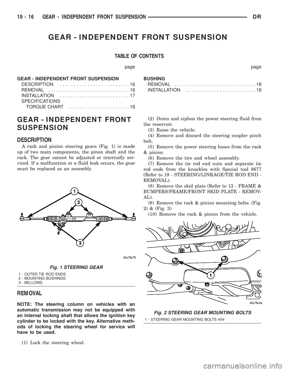
A rack and pinion steering gears (Fig. 1) is made
up of two main components, the pinon shaft and the
rack. The gear cannot be adjusted or internally ser-
viced. If a malfunction or a fluid leak occurs, the gear
must be replaced as an assembly.
REMOVAL
NOTE: The steering column on vehicles with an
automatic transmission may not be equipped with
an internal locking shaft that allows the ignition key
cylinder to be locked with the key. Alternative meth-
ods of locking the steering wheel for service will
have to be used.
(1) Lock the steering wheel.(2) Drain and siphon the power steering fluid from
the reservoir.
(3) Raise the vehicle.
(4) Remove and discard the steering coupler pinch
bolt.
(5) Remove the power steering hoses from the rack
& pinion.
(6) Remove the tire and wheel assembly.
(7) Remove the tie rod end nuts and separate tie
rod ends from the knuckles with Special tool 8677
(Refer to 19 - STEERING/LINKAGE/TIE ROD END -
REMOVAL).
(8) Remove the skid plate (Refer to 13 - FRAME &
BUMPERS/FRAME/FRONT SKID PLATE - REMOV-
AL).
(9) Remove the rack & pinion mounting bolts. (Fig.
2) & (Fig. 3)
(10) Remove the rack & pinion from the vehicle.
Fig. 1 STEERING GEAR
1 - OUTER TIE ROD ENDS
2 - MOUNTING BUSHINGS
3 - BELLOWS
Fig. 2 STEERING GEAR MOUNTING BOLTS
1 - STEERING GEAR MOUNTING BOLTS 4X4
19 - 16 GEAR - INDEPENDENT FRONT SUSPENSIONDR
Page 1812 of 2895
GEAR - LINK/COIL
TABLE OF CONTENTS
page page
GEAR - LINK/COIL
DESCRIPTION.........................19
OPERATION...........................19
REMOVAL.............................19
INSTALLATION.........................20
ADJUSTMENTS
ADJUSTMENT........................20
SPECIFICATIONS
POWER STEERING GEAR..............21
TORQUE CHART......................22
SPECIAL TOOLS
POWER STEERING GEAR..............22
PITMAN SHAFT SEAL
REMOVAL
REMOVAL - GAS ENGINE...............23REMOVAL - DIESEL...................24
INSTALLATION
INSTALLATION - GAS ENGINE...........24
INSTALLATION - DIESEL................25
STEERING GEAR INPUT SHAFT SEAL
REMOVAL.............................25
INSTALLATION.........................28
PITMAN SHAFT
REMOVAL
REMOVAL - GAS......................29
REMOVAL - DIESEL...................30
INSTALLATION
INSTALLATION - GAS..................30
INSTALLATION - DIESEL................30
GEAR - LINK/COIL
DESCRIPTION
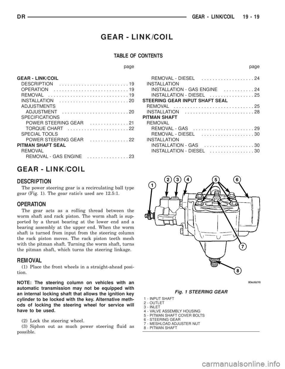
The power steering gear is a recirculating ball type
gear (Fig. 1). The gear ratio's used are 12.5:1.
OPERATION
The gear acts as a rolling thread between the
worm shaft and rack piston. The worm shaft is sup-
ported by a thrust bearing at the lower end and a
bearing assembly at the upper end. When the worm
shaft is turned from input from the steering column
the rack piston moves. The rack piston teeth mesh
with the pitman shaft. Turning the worm shaft, turns
the pitman shaft, which turns the steering linkage.
REMOVAL
(1) Place the front wheels in a straight-ahead posi-
tion.
NOTE: The steering column on vehicles with an
automatic transmission may not be equipped with
an internal locking shaft that allows the ignition key
cylinder to be locked with the key. Alternative meth-
ods of locking the steering wheel for service will
have to be used.
(2) Lock the steering wheel.
(3) Siphon out as much power steering fluid as
possible.
Fig. 1 STEERING GEAR
1 - INPUT SHAFT
2 - OUTLET
3 - INLET
4 - VALVE ASSEMBLY HOUSING
5 - PITMAN SHAFT COVER BOLTS
6 - STEERING GEAR
7 - MESHLOAD ADJUSTER NUT
8 - PITMAN SHAFT
DRGEAR - LINK/COIL 19 - 19
Page 2033 of 2895
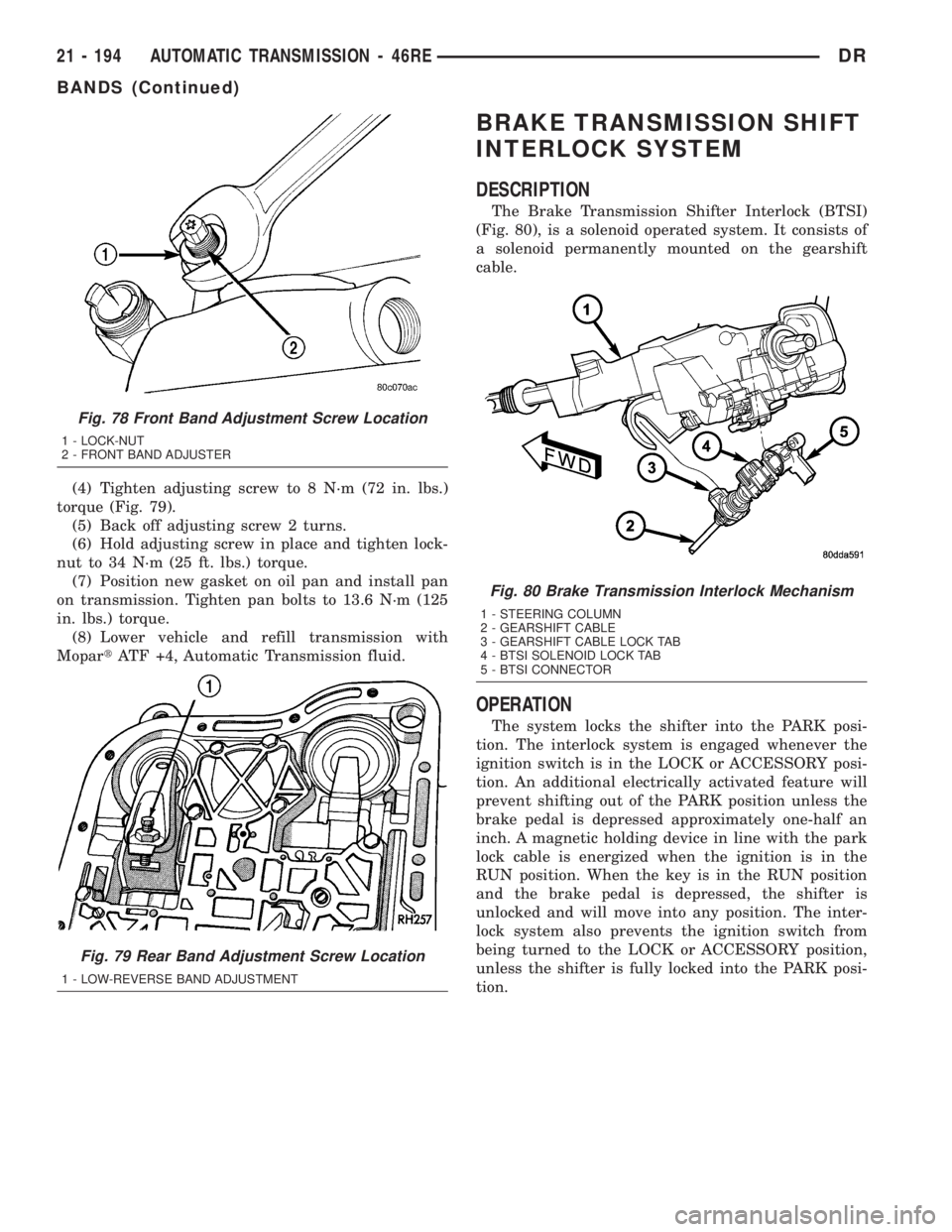
(4) Tighten adjusting screw to 8 N´m (72 in. lbs.)
torque (Fig. 79).
(5) Back off adjusting screw 2 turns.
(6) Hold adjusting screw in place and tighten lock-
nut to 34 N´m (25 ft. lbs.) torque.
(7) Position new gasket on oil pan and install pan
on transmission. Tighten pan bolts to 13.6 N´m (125
in. lbs.) torque.
(8) Lower vehicle and refill transmission with
MopartATF +4, Automatic Transmission fluid.
BRAKE TRANSMISSION SHIFT
INTERLOCK SYSTEM
DESCRIPTION
The Brake Transmission Shifter Interlock (BTSI)
(Fig. 80), is a solenoid operated system. It consists of
a solenoid permanently mounted on the gearshift
cable.
OPERATION
The system locks the shifter into the PARK posi-
tion. The interlock system is engaged whenever the
ignition switch is in the LOCK or ACCESSORY posi-
tion. An additional electrically activated feature will
prevent shifting out of the PARK position unless the
brake pedal is depressed approximately one-half an
inch. A magnetic holding device in line with the park
lock cable is energized when the ignition is in the
RUN position. When the key is in the RUN position
and the brake pedal is depressed, the shifter is
unlocked and will move into any position. The inter-
lock system also prevents the ignition switch from
being turned to the LOCK or ACCESSORY position,
unless the shifter is fully locked into the PARK posi-
tion.
Fig. 78 Front Band Adjustment Screw Location
1 - LOCK-NUT
2 - FRONT BAND ADJUSTER
Fig. 79 Rear Band Adjustment Screw Location
1 - LOW-REVERSE BAND ADJUSTMENT
Fig. 80 Brake Transmission Interlock Mechanism
1 - STEERING COLUMN
2 - GEARSHIFT CABLE
3 - GEARSHIFT CABLE LOCK TAB
4 - BTSI SOLENOID LOCK TAB
5 - BTSI CONNECTOR
21 - 194 AUTOMATIC TRANSMISSION - 46REDR
BANDS (Continued)
Page 2034 of 2895
DIAGNOSIS AND TESTING - BRAKE
TRANSMISSION SHIFT INTERLOCK
(1) Verify that the key can only be removed in the
PARK position
(2) When the shift lever is in PARK And the shift
handle pushbutton is in the ªOUTº position, the igni-
tion key cylinder should rotate freely from OFF to
LOCK. When the shifter is in any other gear or neu-
tral position, the ignition key cylinder should not
rotate to the LOCK position.
(3) Shifting out of PARK should not be possible
when the ignition key cylinder is in the OFF posi-
tion.
(4) Shifting out of PARK should not be possible
while applying normal pushbutton force and ignition
key cylinder is in the RUN or START positions
unless the foot brake pedal is depressed approxi-
mately 1/2 inch (12mm).
(5) Shifting out of PARK should not be possible
when the ignition key cylinder is in the ACCESSORY
or LOCK positions.
(6) Shifting between any gears, NEUTRAL or into
PARK may be done without depressing foot brake
pedal with ignition switch in RUN or START posi-
tions.
ADJUSTMENTS - BRAKE TRANSMISSION
SHIFT INTERLOCK
Correct cable adjustment is important to proper
interlock operation. The gearshift cable must be cor-
rectly adjusted in order to shift out of PARK.
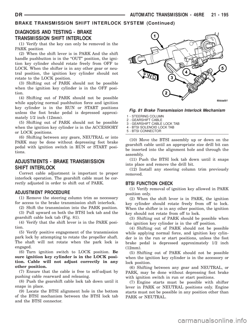
ADJUSTMENT PROCEDURE
(1) Remove the steering column trim as necessary
for access to the brake transmission shift interlock.
(2) Shift the transmission into the PARK position.
(3) Pull upward on both the BTSI lock tab and the
gearshift cable lock tab (Fig. 81).
(4) Verify that the shift lever is in the PARK posi-
tion.
(5) Verify positive engagement of the transmission
park lock by attempting to rotate the propeller shaft.
The shaft will not rotate when the park lock is
engaged.
(6) Turn ignition switch to LOCK position.Be
sure ignition key cylinder is in the LOCK posi-
tion. Cable will not adjust correctly in any
other position.
(7) Ensure that the cable is free to self-adjust by
pushing cable rearward and releasing.
(8) Push the gearshift cable lock tab down until it
snaps in place.
(9) Locate the BTSI alignment hole in the bottom
of the BTSI mechanism between the BTSI lock tab
and the BTSI connector.(10) Move the BTSI assembly up or down on the
gearshift cable until an appropriate size drill bit can
be inserted into the alignment hole and through the
assembly.
(11) Push the BTSI lock tab down until it snaps
into place and remove the drill bit.
(12) Install any steering column trim previously
removed.
BTSI FUNCTION CHECK
(1) Verify removal of ignition key allowed in PARK
position only.
(2) When the shift lever is in PARK, the ignition
key cylinder should rotate freely from off to lock.
When the shifter is in any other position, the ignition
key should not rotate from off to lock.
(3) Shifting out of PARK should be possible when
the ignition key cylinder is in the off position.
(4) Shifting out of PARK should not be possible
while applying normal force, and ignition key cylin-
der is in the run or start positions, unless the foot
brake pedal is depressed approximately 1/2 inch
(12mm).
(5) Shifting out of PARK should not be possible
when the ignition key cylinder is in the accessory or
lock position.
(6) Shifting between any gear and NEUTRAL, or
PARK, may be done without depressing foot brake
with ignition switch in run or start positions.
(7) Engine starts must be possible with shifter
lever in PARK or NEUTRAL positions only. Engine
starts must not be possible in any position other than
PARK or NEUTRAL.
Fig. 81 Brake Transmission Interlock Mechanism
1 - STEERING COLUMN
2 - GEARSHIFT CABLE
3 - GEARSHIFT CABLE LOCK TAB
4 - BTSI SOLENOID LOCK TAB
5 - BTSI CONNECTOR
DRAUTOMATIC TRANSMISSION - 46RE 21 - 195
BRAKE TRANSMISSION SHIFT INTERLOCK SYSTEM (Continued)
Page 2057 of 2895
OVERDRIVE CLUTCH
DESCRIPTION
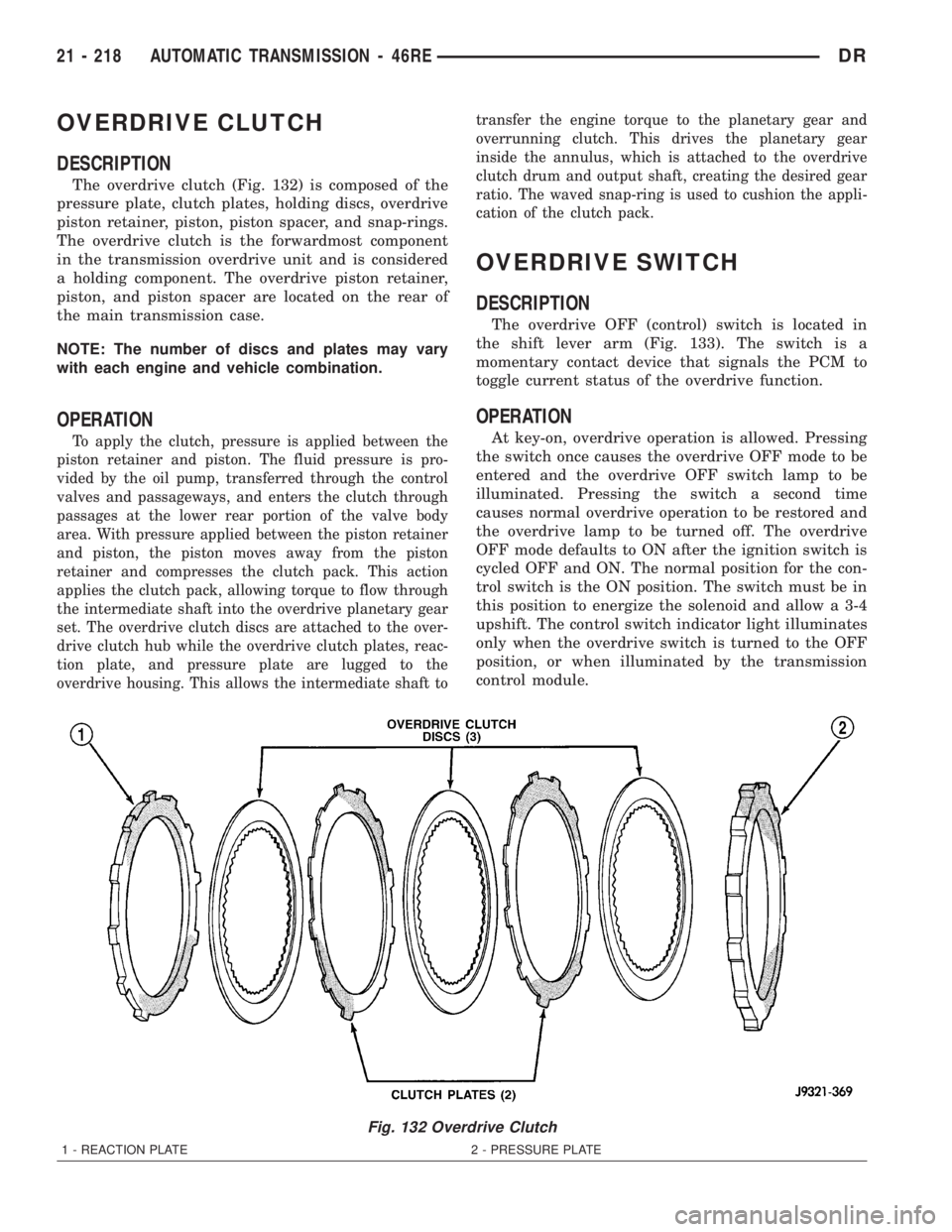
The overdrive clutch (Fig. 132) is composed of the
pressure plate, clutch plates, holding discs, overdrive
piston retainer, piston, piston spacer, and snap-rings.
The overdrive clutch is the forwardmost component
in the transmission overdrive unit and is considered
a holding component. The overdrive piston retainer,
piston, and piston spacer are located on the rear of
the main transmission case.
NOTE: The number of discs and plates may vary
with each engine and vehicle combination.
OPERATION
To apply the clutch, pressure is applied between the
piston retainer and piston. The fluid pressure is pro-
vided by the oil pump, transferred through the control
valves and passageways, and enters the clutch through
passages at the lower rear portion of the valve body
area. With pressure applied between the piston retainer
and piston, the piston moves away from the piston
retainer and compresses the clutch pack. This action
applies the clutch pack, allowing torque to flow through
the intermediate shaft into the overdrive planetary gear
set. The overdrive clutch discs are attached to the over-
drive clutch hub while the overdrive clutch plates, reac-
tion plate, and pressure plate are lugged to the
overdrive housing. This allows the intermediate shaft totransfer the engine torque to the planetary gear and
overrunning clutch. This drives the planetary gear
inside the annulus, which is attached to the overdrive
clutch drum and output shaft, creating the desired gear
ratio. The waved snap-ring is used to cushion the appli-
cation of the clutch pack.
OVERDRIVE SWITCH
DESCRIPTION
The overdrive OFF (control) switch is located in
the shift lever arm (Fig. 133). The switch is a
momentary contact device that signals the PCM to
toggle current status of the overdrive function.
OPERATION
At key-on, overdrive operation is allowed. Pressing
the switch once causes the overdrive OFF mode to be
entered and the overdrive OFF switch lamp to be
illuminated. Pressing the switch a second time
causes normal overdrive operation to be restored and
the overdrive lamp to be turned off. The overdrive
OFF mode defaults to ON after the ignition switch is
cycled OFF and ON. The normal position for the con-
trol switch is the ON position. The switch must be in
this position to energize the solenoid and allow a 3-4
upshift. The control switch indicator light illuminates
only when the overdrive switch is turned to the OFF
position, or when illuminated by the transmission
control module.
Fig. 132 Overdrive Clutch
1 - REACTION PLATE 2 - PRESSURE PLATE
21 - 218 AUTOMATIC TRANSMISSION - 46REDR
Page 2094 of 2895
ADJUSTMENTS - THROTTLE VALVE CABLE
A correctly adjusted throttle valve cable will cause
the throttle lever on the transmission to move simul-
taneously with the throttle body lever from the idle
position. Proper adjustment will allow simultaneous
movement without causing the transmission throttle
lever to either move ahead of, or lag behind the lever
on the throttle body.
ADJUSTMENT VERIFICATION
(1) Turn ignition key to OFF position.
(2) Remove air cleaner.
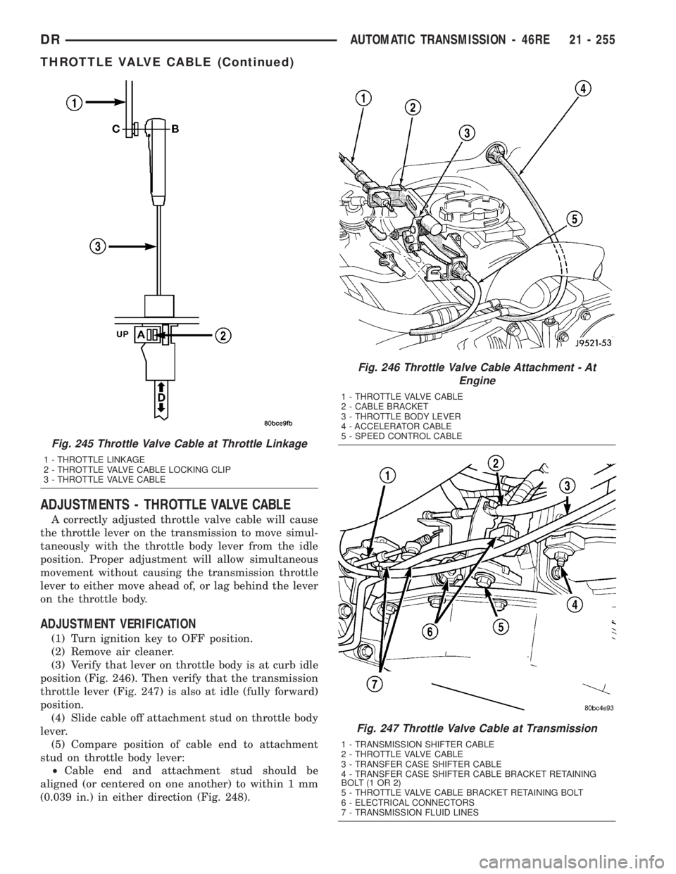
(3) Verify that lever on throttle body is at curb idle
position (Fig. 246). Then verify that the transmission
throttle lever (Fig. 247) is also at idle (fully forward)
position.
(4) Slide cable off attachment stud on throttle body
lever.
(5) Compare position of cable end to attachment
stud on throttle body lever:
²Cable end and attachment stud should be
aligned (or centered on one another) to within 1 mm
(0.039 in.) in either direction (Fig. 248).
Fig. 245 Throttle Valve Cable at Throttle Linkage
1 - THROTTLE LINKAGE
2 - THROTTLE VALVE CABLE LOCKING CLIP
3 - THROTTLE VALVE CABLE
Fig. 246 Throttle Valve Cable Attachment - At
Engine
1 - THROTTLE VALVE CABLE
2 - CABLE BRACKET
3 - THROTTLE BODY LEVER
4 - ACCELERATOR CABLE
5 - SPEED CONTROL CABLE
Fig. 247 Throttle Valve Cable at Transmission
1 - TRANSMISSION SHIFTER CABLE
2 - THROTTLE VALVE CABLE
3 - TRANSFER CASE SHIFTER CABLE
4 - TRANSFER CASE SHIFTER CABLE BRACKET RETAINING
BOLT(1OR2)
5 - THROTTLE VALVE CABLE BRACKET RETAINING BOLT
6 - ELECTRICAL CONNECTORS
7 - TRANSMISSION FLUID LINES
DRAUTOMATIC TRANSMISSION - 46RE 21 - 255
THROTTLE VALVE CABLE (Continued)