2003 DODGE RAM engine
[x] Cancel search: enginePage 685 of 2895

The washer fluid level switch is connected to the
vehicle electrical system through a dedicated take
out and connector of the right (except V-10 and diesel
engines) or left (V-10 and diesel engines only) head-
lamp and dash wire harness. The switch is connected
in series between a clean ground output of the Front
Control Module (FCM) on a sensor return circuit and
the washer fluid switch sense input to the FCM.
When the switch closes, the FMC senses the ground
on the washer fluid switch sense circuit. The FMC is
programmed to respond to this input by sending an
electronic washer fluid indicator lamp-on message to
the instrument cluster over the Programmable Com-
munications Interface (PCI) data bus. The instru-
ment cluster responds to this message by
illuminating the washer fluid indicator and by sound-
ing an audible chime tone warning.
The washer fluid level switch may be diagnosed
and tested using conventional diagnostic tools and
procedures. However, conventional diagnostic meth-
ods may not prove conclusive in the diagnosis of the
instrument cluster, the Front Control Module (FCM),
or the electronic message inputs to or outputs from
the instrument cluster and the FCM that control the
operation of the washer fluid visual and/or audible
indicators. The most reliable, efficient, and accurate
means to diagnose the washer fluid level indicator,
the instrument cluster, the FCM, or the electronic
message inputs and outputs related to the washer
fluid indicator requires the use of a DRBIIItscan
tool. Refer to the appropriate diagnostic information.
REMOVAL
The washer fluid level switch can be removed from
the washer reservoir without removing the reservoir
from the vehicle.
(1) Unlatch and open the hood.
(2) Disconnect and isolate the battery negative
cable.
(3) Disconnect the washer hose from the barbed
outlet nipple of the washer pump/motor unit and
allow the washer fluid to drain into a clean container
for reuse.
(4) Disconnect the right (except V-10 and diesel
engine) or left (V-10 and diesel engine only) head-
lamp and dash wire harness connector for the washer
fluid level switch from the switch connector recepta-
cle (Fig. 7) or (Fig. 8).
NOTE: The pivoting float of the washer fluid level
switch must be in a horizontal position within the
reservoir in order to be removed. With the reservoir
empty and in an upright position, the pivoting float
will orient itself to the horizontal position when the
switch connector receptacle is pointed straight
upwards.(5) Using a trim stick or another suitable wide
flat-bladed tool, gently pry the barbed nipple of the
washer fluid level switch out of the rubber grommet
seal on the reservoir sump. Care must be taken not
to damage the reservoir.
Fig. 7 Washer Fluid Level Switch Remove/Install -
Except V-10 & Diesel Engine
1 - WASHER HOSE
2 - WASHER RESERVOIR
3 - WASHER FLUID LEVEL SWITCH
4 - WIRE HARNESS
5 - WASHER PUMP/MOTOR
Fig. 8 Washer Fluid Level Switch Remove/Install -
V-10 & Diesel Engine
1 - WIRE HARNESS
2 - WASHER RESERVOIR
3 - WASHER PUMP/MOTOR
4 - WASHER HOSE
5 - WASHER FLUID LEVEL SWITCH
8R - 10 WIPERS/WASHERSDR
WASHER FLUID LEVEL SWITCH (Continued)
Page 686 of 2895
(6) Remove the washer fluid level switch from the
washer reservoir.
(7) Remove the rubber grommet seal from the
washer fluid level switch mounting hole in the
washer reservoir and discard.
INSTALLATION
(1) Install a new rubber grommet seal into the
washer fluid level switch mounting hole in the
washer reservoir. Always use a new rubber grommet
seal on the reservoir.
(2) Insert the float of the washer fluid level switch
through the rubber grommet seal and into the
washer reservoir. The connector receptacle of the
washer fluid level switch should be pointed upward.
(3) Using hand pressure, press firmly and evenly
on the washer fluid level switch mounting flange
until the barbed nipple is fully seated in the rubber
grommet seal in the washer reservoir mounting hole.
(4) Reconnect the right (except V-10 and diesel
engine) or left (V-10 and diesel engine only) head-
lamp and dash wire harness connector for the washer
fluid level switch to the switch connector receptacle
(Fig. 7) or (Fig. 8).
(5) Reconnect the removed washer hose to the
barbed outlet nipple of the washer pump/motor unit.
(6) Refill the washer reservoir with the washer
fluid drained from the reservoir during the removal
procedure.
(7) Reconnect the battery negative cable.
(8) Close and latch the hood.
WASHER HOSES/TUBES
DESCRIPTION
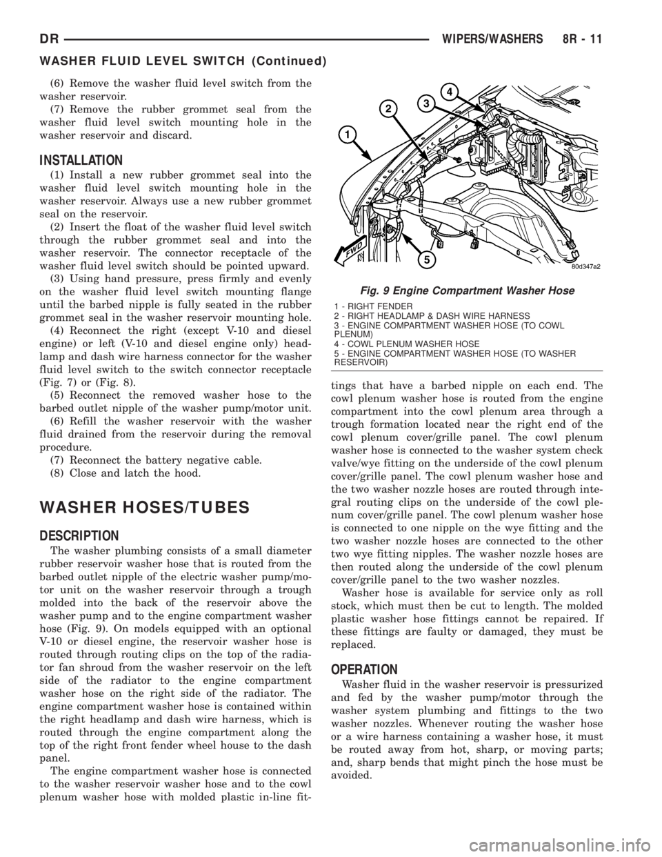
The washer plumbing consists of a small diameter
rubber reservoir washer hose that is routed from the
barbed outlet nipple of the electric washer pump/mo-
tor unit on the washer reservoir through a trough
molded into the back of the reservoir above the
washer pump and to the engine compartment washer
hose (Fig. 9). On models equipped with an optional
V-10 or diesel engine, the reservoir washer hose is
routed through routing clips on the top of the radia-
tor fan shroud from the washer reservoir on the left
side of the radiator to the engine compartment
washer hose on the right side of the radiator. The
engine compartment washer hose is contained within
the right headlamp and dash wire harness, which is
routed through the engine compartment along the
top of the right front fender wheel house to the dash
panel.
The engine compartment washer hose is connected
to the washer reservoir washer hose and to the cowl
plenum washer hose with molded plastic in-line fit-tings that have a barbed nipple on each end. The
cowl plenum washer hose is routed from the engine
compartment into the cowl plenum area through a
trough formation located near the right end of the
cowl plenum cover/grille panel. The cowl plenum
washer hose is connected to the washer system check
valve/wye fitting on the underside of the cowl plenum
cover/grille panel. The cowl plenum washer hose and
the two washer nozzle hoses are routed through inte-
gral routing clips on the underside of the cowl ple-
num cover/grille panel. The cowl plenum washer hose
is connected to one nipple on the wye fitting and the
two washer nozzle hoses are connected to the other
two wye fitting nipples. The washer nozzle hoses are
then routed along the underside of the cowl plenum
cover/grille panel to the two washer nozzles.
Washer hose is available for service only as roll
stock, which must then be cut to length. The molded
plastic washer hose fittings cannot be repaired. If
these fittings are faulty or damaged, they must be
replaced.
OPERATION
Washer fluid in the washer reservoir is pressurized
and fed by the washer pump/motor through the
washer system plumbing and fittings to the two
washer nozzles. Whenever routing the washer hose
or a wire harness containing a washer hose, it must
be routed away from hot, sharp, or moving parts;
and, sharp bends that might pinch the hose must be
avoided.
Fig. 9 Engine Compartment Washer Hose
1 - RIGHT FENDER
2 - RIGHT HEADLAMP & DASH WIRE HARNESS
3 - ENGINE COMPARTMENT WASHER HOSE (TO COWL
PLENUM)
4 - COWL PLENUM WASHER HOSE
5 - ENGINE COMPARTMENT WASHER HOSE (TO WASHER
RESERVOIR)
DRWIPERS/WASHERS 8R - 11
WASHER FLUID LEVEL SWITCH (Continued)
Page 688 of 2895
(4) Reinstall the washer hose for the washer noz-
zle into its routing clips on the underside of the cowl
plenum cover/grille panel.
(5) Reinstall the cowl plenum cover/grille panel
over the cowl plenum. (Refer to 23 - BODY/EXTERI-
OR/COWL GRILLE - INSTALLATION).
(6) Close and latch the hood.
(7) Reinstall both wiper arms onto the wiper piv-
ots. (Refer to 8 - ELECTRICAL/WIPERS/WASHERS/
WIPER ARM - INSTALLATION).
WASHER PUMP/MOTOR
DESCRIPTION
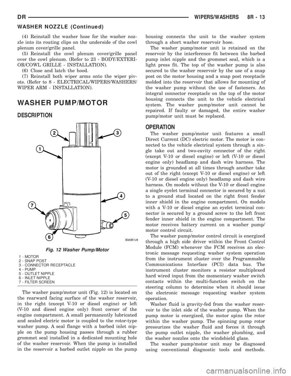
The washer pump/motor unit (Fig. 12) is located on
the rearward facing surface of the washer reservoir,
in the right (except V-10 or diesel engine) or left
(V-10 and diesel engine only) front corner of the
engine compartment. A small permanently lubricated
and sealed electric motor is coupled to the rotor-type
washer pump. A seal flange with a barbed inlet nip-
ple on the pump housing passes through a rubber
grommet seal installed in a dedicated mounting hole
of the washer reservoir. When the pump is installed
in the reservoir a barbed outlet nipple on the pumphousing connects the unit to the washer system
through a short washer reservoir hose.
The washer pump/motor unit is retained on the
reservoir by the interference fit between the barbed
pump inlet nipple and the grommet seal, which is a
light press fit. The top of the washer pump is also
secured to the washer reservoir by the use of a snap
post on the motor housing and a snap post receptacle
molded into the reservoir that allows for mounting of
the washer pump without the use of fasteners. An
integral connector receptacle on the top of the motor
housing connects the unit to the vehicle electrical
system. The washer pump/motor unit cannot be
repaired. If faulty or damaged, the entire washer
pump/motor unit must be replaced.
OPERATION
The washer pump/motor unit features a small
Direct Current (DC) electric motor. The motor is con-
nected to the vehicle electrical system through a sin-
gle take out and two-cavity connector of the right
(except V-10 or diesel engine) or left (V-10 or diesel
engine only) headlamp and dash wire harness. The
motor is grounded at all times through another take
out of the right (except V-10 or diesel engine) or left
(V-10 or diesel engine only) headlamp and dash wire
harness. On models without the V-10 or diesel engine
a single eyelet terminal connector is secured by a nut
to a ground stud located on the right front fender
inner shield in the engine compartment. On models
with a V-10 or diesel engine an eyelet terminal con-
nector is secured by a ground screw to the left front
fender inner shield in the engine compartment. The
motor receives battery current on a washer pump/
motor control circuit.
The washer pump/motor control circuit is energized
through a high side driver within the Front Control
Module (FCM) whenever the FCM receives an elec-
tronic message requesting washer system operation
from the instrument cluster over the Programmable
Communications Interface (PCI) data bus. The
instrument cluster monitors a resistor multiplexed
hard wired input from the momentary washer switch
contacts within the multi-function switch on the
steering column to determine when it should issue
the electronic message requesting washer system
operation.
Washer fluid is gravity-fed from the washer reser-
voir to the inlet side of the washer pump. When the
pump motor is energized, the motor spins the rotor
within the washer pump. The spinning pump rotor
pressurizes the washer fluid and forces it through
the pump outlet nipple, the washer plumbing, and
the washer nozzles onto the windshield glass.
The washer pump/motor unit may be diagnosed
using conventional diagnostic tools and methods.
Fig. 12 Washer Pump/Motor
1 - MOTOR
2 - SNAP POST
3 - CONNECTOR RECEPTACLE
4 - PUMP
5 - OUTLET NIPPLE
6 - INLET NIPPLE
7 - FILTER SCREEN
DRWIPERS/WASHERS 8R - 13
WASHER NOZZLE (Continued)
Page 689 of 2895
However, conventional diagnostic methods may not
prove conclusive in the diagnosis of the instrument
cluster, the Front Control Module (FCM), or the elec-
tronic message inputs to or outputs from the instru-
ment cluster and the FCM that control the operation
of the washer pump/motor unit. The most reliable,
efficient, and accurate means to diagnose the washer
pump/motor unit, the instrument cluster, the FCM,
or the electronic message inputs and outputs related
to the washer pump/motor unit operation requires
the use of a DRBIIItscan tool. Refer to the appro-
priate diagnostic information.
REMOVAL
The washer pump/motor unit can be removed from
the washer reservoir without removing the reservoir
from the vehicle.
(1) Unlatch and open the hood.
(2) Disconnect and isolate the battery negative
cable.
(3) Disconnect the washer hose from the barbed
outlet nipple of the washer pump/motor unit and
allow the washer fluid to drain into a clean container
for reuse.
(4) Disconnect the right (except V-10 or diesel
engine) or left (V-10 or diesel engine only) headlamp
and dash wire harness connector for the washer
pump/motor unit from the motor connector receptacle
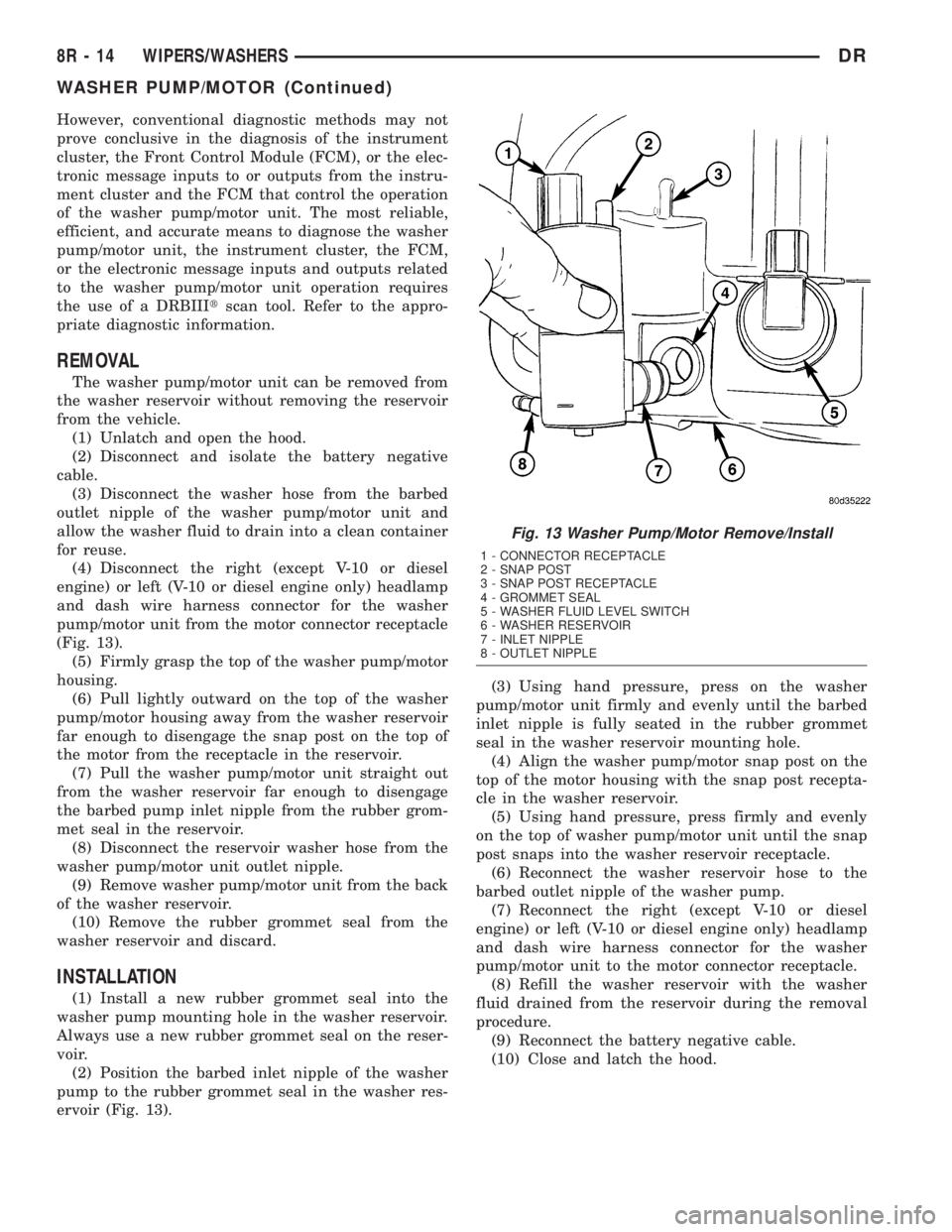
(Fig. 13).
(5) Firmly grasp the top of the washer pump/motor
housing.
(6) Pull lightly outward on the top of the washer
pump/motor housing away from the washer reservoir
far enough to disengage the snap post on the top of
the motor from the receptacle in the reservoir.
(7) Pull the washer pump/motor unit straight out
from the washer reservoir far enough to disengage
the barbed pump inlet nipple from the rubber grom-
met seal in the reservoir.
(8) Disconnect the reservoir washer hose from the
washer pump/motor unit outlet nipple.
(9) Remove washer pump/motor unit from the back
of the washer reservoir.
(10) Remove the rubber grommet seal from the
washer reservoir and discard.
INSTALLATION
(1) Install a new rubber grommet seal into the
washer pump mounting hole in the washer reservoir.
Always use a new rubber grommet seal on the reser-
voir.
(2) Position the barbed inlet nipple of the washer
pump to the rubber grommet seal in the washer res-
ervoir (Fig. 13).(3) Using hand pressure, press on the washer
pump/motor unit firmly and evenly until the barbed
inlet nipple is fully seated in the rubber grommet
seal in the washer reservoir mounting hole.
(4) Align the washer pump/motor snap post on the
top of the motor housing with the snap post recepta-
cle in the washer reservoir.
(5) Using hand pressure, press firmly and evenly
on the top of washer pump/motor unit until the snap
post snaps into the washer reservoir receptacle.
(6) Reconnect the washer reservoir hose to the
barbed outlet nipple of the washer pump.
(7) Reconnect the right (except V-10 or diesel
engine) or left (V-10 or diesel engine only) headlamp
and dash wire harness connector for the washer
pump/motor unit to the motor connector receptacle.
(8) Refill the washer reservoir with the washer
fluid drained from the reservoir during the removal
procedure.
(9) Reconnect the battery negative cable.
(10) Close and latch the hood.
Fig. 13 Washer Pump/Motor Remove/Install
1 - CONNECTOR RECEPTACLE
2 - SNAP POST
3 - SNAP POST RECEPTACLE
4 - GROMMET SEAL
5 - WASHER FLUID LEVEL SWITCH
6 - WASHER RESERVOIR
7 - INLET NIPPLE
8 - OUTLET NIPPLE
8R - 14 WIPERS/WASHERSDR
WASHER PUMP/MOTOR (Continued)
Page 690 of 2895

WASHER RESERVOIR
DESCRIPTION
Except on models equipped with an optional V-10
or diesel engine, the molded plastic washer fluid res-
ervoir is mounted on the right rearward facing sur-
face of the cooling module radiator shroud in the
engine compartment (Fig. 14). On models with the
V-10 or diesel engine, the molded plastic washer fluid
reservoir is mounted on the rearward facing surface
of the left vertical member of the radiator support in
the engine compartment. The reservoir is a molded
unit constructed of a translucent plastic that allows
the washer fluid level to be inspected without remov-
ing the washer reservoir cap. The most visible com-
ponent of the washer reservoir is the filler cap unit,
which is secured to and hinges on a hook feature
that is integral to the filler neck near the top of the
reservoir. The bright yellow plastic filler cap snaps
over the filler neck opening and seals the reservoiropening with an integral rubber gasket. The filler
cap is labeled with an International Control and Dis-
play Symbol icon for ªWindshield Washerº and the
text ªWasher Fluid Onlyº that are molded into it and
highlighted in black against the yellow plastic cap for
visibility.
There are dedicated holes near the bottom of the
rearward facing side of the reservoir provided for the
mounting of the washer pump/motor unit and the
washer fluid level switch. A snap post receptacle
molded into the reservoir allows for mounting of the
washer pump without the use of fasteners. The res-
ervoir also features an integral hose routing trough
on its rearward facing side. Except on models with a
V-10 or diesel engine, the washer reservoir is secured
to the cooling module radiator shroud with three
integral tabs, two at the bottom and one at the top.
The two bottom tabs are inserted into two slots near
the bottom of the shroud, while the upper tab slides
into an integral channel-like slot near the top of the
shroud. A molded lock feature on the forward facing
surface of the reservoir engages a molded depression
on the rearward facing surface of the radiator shroud
when the reservoir is fully seated on the shroud,
locking the unit securely in place. On models with a
V-10 or diesel engine, the washer reservoir is secured
with two screws through integral mounting tabs to
the left vertical member of the radiator support. On
many models, a molded plastic coolant recovery con-
tainer or a coolant pressure container must be
detached from the top of the cooling module and
moved aside to access the washer fluid reservoir for
service. This may be accomplished without opening
or draining the engine cooling system.
OPERATION
The washer fluid reservoir provides a secure,
on-vehicle storage location for a large reserve of
washer fluid for operation of the washer system. The
washer reservoir filler neck provides a clearly
marked and readily accessible point from which to
add washer fluid to the reservoir. The washer/pump
motor unit is located in a sump area near the bottom
of the reservoir to be certain that washer fluid will
be available to the pump as the fluid level in the res-
ervoir becomes depleted. The washer pump/motor
unit is mounted in the lowest position in the sump.
The washer fluid level switch is mounted just above
the sump area of the reservoir so that there will be
adequate warning to the vehicle operator that the
washer fluid level is low, well before the washer sys-
tem will no longer operate.
Fig. 14 Washer Reservoir - except V-10 & Diesel
Engine
1-TOPTAB
2 - HOOK FEATURE
3 - CAP
4 - RESERVOIR
5 - TROUGH
6 - HOSE
7 - LOCK FEATURE
8 - WASHER FLUID LEVEL SWITCH
9 - WASHER PUMP/MOTOR
10 - BOTTOM TAB (2)
DRWIPERS/WASHERS 8R - 15
Page 691 of 2895
REMOVAL
REMOVAL - EXCEPT V-10 OR DIESEL ENGINE
(1) Unlatch and open the hood.
(2) Disconnect and isolate the battery negative
cable.
(3) Remove the fasteners securing the coolant
recovery container or the coolant pressure container
to the top of the cooling module and move the con-
tainer aside. It is not necessary to open or drain the
engine cooling system. (Refer to 7 - COOLING/EN-
GINE/COOLANT RECOVERY CONTAINER -
REMOVAL) or (Refer to 7 - COOLING/ENGINE/
COOLANT RECOVERY PRESSURE CONTAINER -
REMOVAL).
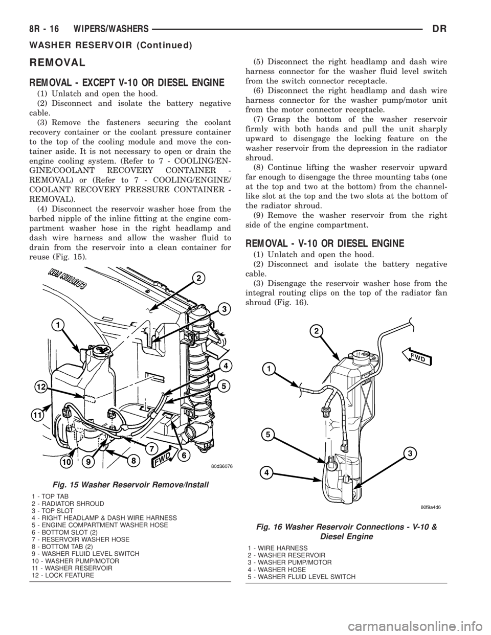
(4) Disconnect the reservoir washer hose from the
barbed nipple of the inline fitting at the engine com-
partment washer hose in the right headlamp and
dash wire harness and allow the washer fluid to
drain from the reservoir into a clean container for
reuse (Fig. 15).(5) Disconnect the right headlamp and dash wire
harness connector for the washer fluid level switch
from the switch connector receptacle.
(6) Disconnect the right headlamp and dash wire
harness connector for the washer pump/motor unit
from the motor connector receptacle.
(7) Grasp the bottom of the washer reservoir
firmly with both hands and pull the unit sharply
upward to disengage the locking feature on the
washer reservoir from the depression in the radiator
shroud.
(8) Continue lifting the washer reservoir upward
far enough to disengage the three mounting tabs (one
at the top and two at the bottom) from the channel-
like slot at the top and the two slots at the bottom of
the radiator shroud.
(9) Remove the washer reservoir from the right
side of the engine compartment.
REMOVAL - V-10 OR DIESEL ENGINE
(1) Unlatch and open the hood.
(2) Disconnect and isolate the battery negative
cable.
(3) Disengage the reservoir washer hose from the
integral routing clips on the top of the radiator fan
shroud (Fig. 16).
Fig. 15 Washer Reservoir Remove/Install
1-TOPTAB
2 - RADIATOR SHROUD
3 - TOP SLOT
4 - RIGHT HEADLAMP & DASH WIRE HARNESS
5 - ENGINE COMPARTMENT WASHER HOSE
6 - BOTTOM SLOT (2)
7 - RESERVOIR WASHER HOSE
8 - BOTTOM TAB (2)
9 - WASHER FLUID LEVEL SWITCH
10 - WASHER PUMP/MOTOR
11 - WASHER RESERVOIR
12 - LOCK FEATURE
Fig. 16 Washer Reservoir Connections - V-10 &
Diesel Engine
1 - WIRE HARNESS
2 - WASHER RESERVOIR
3 - WASHER PUMP/MOTOR
4 - WASHER HOSE
5 - WASHER FLUID LEVEL SWITCH
8R - 16 WIPERS/WASHERSDR
WASHER RESERVOIR (Continued)
Page 692 of 2895
(4) Disconnect the reservoir washer hose from the
barbed nipple of the inline fitting at the engine com-
partment washer hose in the right headlamp and
dash wire harness and allow the washer fluid to
drain from the reservoir into a clean container for
reuse.
(5) Disconnect the left headlamp and dash wire
harness connector for the washer fluid level switch
from the switch connector receptacle.
(6) Disconnect the left headlamp and dash wire
harness connector for the washer pump/motor unit
from the motor connector receptacle.
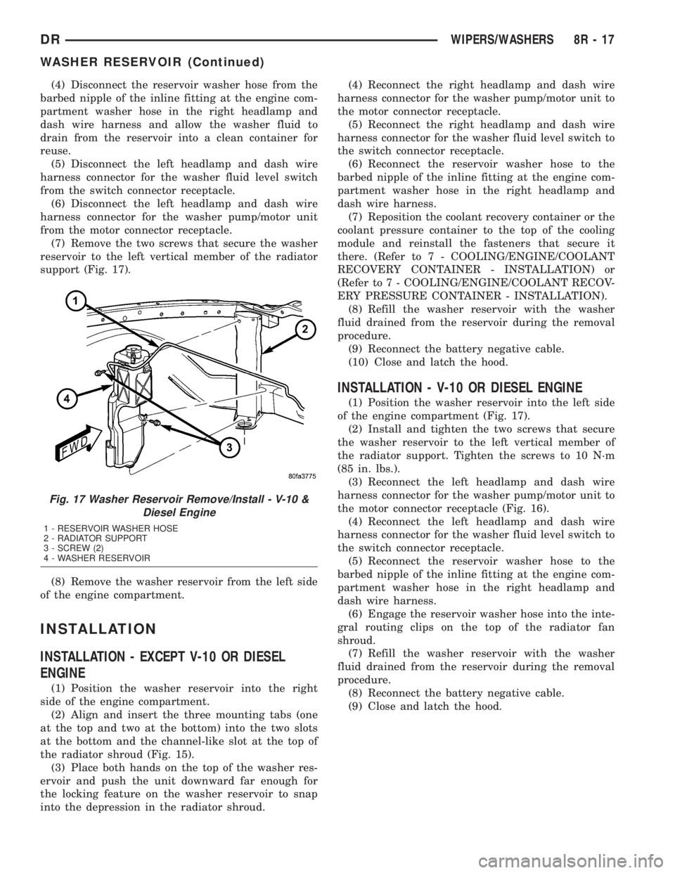
(7) Remove the two screws that secure the washer
reservoir to the left vertical member of the radiator
support (Fig. 17).
(8) Remove the washer reservoir from the left side
of the engine compartment.
INSTALLATION
INSTALLATION - EXCEPT V-10 OR DIESEL
ENGINE
(1) Position the washer reservoir into the right
side of the engine compartment.
(2) Align and insert the three mounting tabs (one
at the top and two at the bottom) into the two slots
at the bottom and the channel-like slot at the top of
the radiator shroud (Fig. 15).
(3) Place both hands on the top of the washer res-
ervoir and push the unit downward far enough for
the locking feature on the washer reservoir to snap
into the depression in the radiator shroud.(4) Reconnect the right headlamp and dash wire
harness connector for the washer pump/motor unit to
the motor connector receptacle.
(5) Reconnect the right headlamp and dash wire
harness connector for the washer fluid level switch to
the switch connector receptacle.
(6) Reconnect the reservoir washer hose to the
barbed nipple of the inline fitting at the engine com-
partment washer hose in the right headlamp and
dash wire harness.
(7) Reposition the coolant recovery container or the
coolant pressure container to the top of the cooling
module and reinstall the fasteners that secure it
there. (Refer to 7 - COOLING/ENGINE/COOLANT
RECOVERY CONTAINER - INSTALLATION) or
(Refer to 7 - COOLING/ENGINE/COOLANT RECOV-
ERY PRESSURE CONTAINER - INSTALLATION).
(8) Refill the washer reservoir with the washer
fluid drained from the reservoir during the removal
procedure.
(9) Reconnect the battery negative cable.
(10) Close and latch the hood.
INSTALLATION - V-10 OR DIESEL ENGINE
(1) Position the washer reservoir into the left side
of the engine compartment (Fig. 17).
(2) Install and tighten the two screws that secure
the washer reservoir to the left vertical member of
the radiator support. Tighten the screws to 10 N´m
(85 in. lbs.).
(3) Reconnect the left headlamp and dash wire
harness connector for the washer pump/motor unit to
the motor connector receptacle (Fig. 16).
(4) Reconnect the left headlamp and dash wire
harness connector for the washer fluid level switch to
the switch connector receptacle.
(5) Reconnect the reservoir washer hose to the
barbed nipple of the inline fitting at the engine com-
partment washer hose in the right headlamp and
dash wire harness.
(6) Engage the reservoir washer hose into the inte-
gral routing clips on the top of the radiator fan
shroud.
(7) Refill the washer reservoir with the washer
fluid drained from the reservoir during the removal
procedure.
(8) Reconnect the battery negative cable.
(9) Close and latch the hood.
Fig. 17 Washer Reservoir Remove/Install - V-10 &
Diesel Engine
1 - RESERVOIR WASHER HOSE
2 - RADIATOR SUPPORT
3 - SCREW (2)
4 - WASHER RESERVOIR
DRWIPERS/WASHERS 8R - 17
WASHER RESERVOIR (Continued)
Page 695 of 2895
(3) Extract the hook formation on the tip of the
wiper arm through the opening in the wiper blade
superstructure just ahead of the wiper blade pivot
block/latch unit.
CAUTION: Do not allow the wiper arm to spring
back against the glass without the wiper blade in
place or the glass may be damaged.
(4) Gently lower the tip of the wiper arm onto the
glass.
INSTALLATION
NOTE: The notched end of the wiper element flexor
should always be oriented towards the end of the
wiper blade that is nearest to the wiper pivot.
(1)
Lift the wiper arm off of the windshield glass,
until the wiper arm hinge is in its over-center position.
(2) Position the wiper blade near the hook forma-
tion on the tip of the arm with the notched end of the
wiper element flexor oriented towards the end of the
wiper arm that is nearest to the wiper pivot.
(3) Insert the hook formation on the tip of the
wiper arm through the opening in the wiper blade
superstructure ahead of the wiper blade pivot block/
latch unit far enough to engage the pivot block into
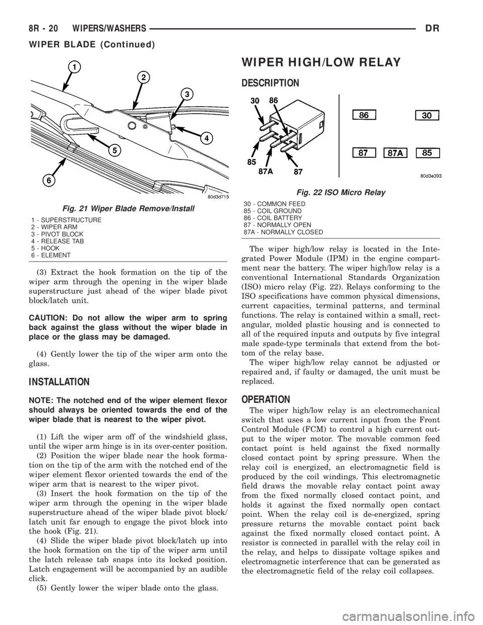
the hook (Fig. 21).
(4) Slide the wiper blade pivot block/latch up into
the hook formation on the tip of the wiper arm until
the latch release tab snaps into its locked position.
Latch engagement will be accompanied by an audible
click.
(5) Gently lower the wiper blade onto the glass.
WIPER HIGH/LOW RELAY
DESCRIPTION
The wiper high/low relay is located in the Inte-
grated Power Module (IPM) in the engine compart-
ment near the battery. The wiper high/low relay is a
conventional International Standards Organization
(ISO) micro relay (Fig. 22). Relays conforming to the
ISO specifications have common physical dimensions,
current capacities, terminal patterns, and terminal
functions. The relay is contained within a small, rect-
angular, molded plastic housing and is connected to
all of the required inputs and outputs by five integral
male spade-type terminals that extend from the bot-
tom of the relay base.
The wiper high/low relay cannot be adjusted or
repaired and, if faulty or damaged, the unit must be
replaced.
OPERATION
The wiper high/low relay is an electromechanical
switch that uses a low current input from the Front
Control Module (FCM) to control a high current out-
put to the wiper motor. The movable common feed
contact point is held against the fixed normally
closed contact point by spring pressure. When the
relay coil is energized, an electromagnetic field is
produced by the coil windings. This electromagnetic
field draws the movable relay contact point away
from the fixed normally closed contact point, and
holds it against the fixed normally open contact
point. When the relay coil is de-energized, spring
pressure returns the movable contact point back
against the fixed normally closed contact point. A
resistor is connected in parallel with the relay coil in
the relay, and helps to dissipate voltage spikes and
electromagnetic interference that can be generated as
the electromagnetic field of the relay coil collapses.
Fig. 21 Wiper Blade Remove/Install
1 - SUPERSTRUCTURE
2 - WIPER ARM
3 - PIVOT BLOCK
4 - RELEASE TAB
5 - HOOK
6 - ELEMENT
Fig. 22 ISO Micro Relay
30 - COMMON FEED
85 - COIL GROUND
86 - COIL BATTERY
87 - NORMALLY OPEN
87A - NORMALLY CLOSED
8R - 20 WIPERS/WASHERSDR
WIPER BLADE (Continued)