2003 DODGE RAM check transmission fluid
[x] Cancel search: check transmission fluidPage 499 of 2895

ule must be replaced. The cluster lens, hood and
mask unit and the individual incandescent lamp
bulbs with holders are available for individual ser-
vice replacement.
OPERATION
The ElectroMechanical Instrument Cluster (EMIC)
in this model also includes the hardware and soft-
ware necessary to serve as the electronic body control
module and is sometimes referred to as the Cab
Compartment Node or CCN. The following informa-
tion deals primarily with the instrument cluster
functions of this unit. Additional details of the elec-
tronic body control functions of this unit may be
found within the service information for the system
or component that the EMIC controls. For example:
Additional details of the audible warning functions of
the EMIC are found within the Chime/Buzzer service
information.The EMIC is designed to allow the vehicle operator
to monitor the conditions of many of the vehicle com-
ponents and operating systems. The gauges and indi-
cators in the EMIC provide valuable information
about the various standard and optional powertrains,
fuel and emissions systems, cooling systems, lighting
systems, safety systems and many other convenience
items. The EMIC is installed in the instrument panel
so that all of these monitors can be easily viewed by
the vehicle operator when driving, while still allow-
ing relative ease of access for service. The micropro-
cessor-based EMIC hardware and software uses
various inputs to control the gauges and indicators
visible on the face of the cluster. Some of these
inputs are hard wired, but most are in the form of
electronic messages that are transmitted by other
electronic modules over the Programmable Communi-
cations Interface (PCI) data bus network. (Refer to 8
- ELECTRICAL/ELECTRONIC CONTROL MOD-
ULES/COMMUNICATION - OPERATION).
Fig. 3 Gauges & Indicators - Gasoline Engine
1 - MALFUNCTION INDICATOR LAMP 13 - ELECTRONIC THROTTLE CONTROL (ETC) INDICATOR
2 - VOLTAGE GAUGE 14 - ENGINE TEMPERATURE GAUGE
3 - LEFT TURN INDICATOR 15 - SECURITY INDICATOR
4 - TACHOMETER 16 - GEAR SELECTOR INDICATOR DISPLAY (INCLUDES
CRUISE & UPSHIFT INDICATORS)
5 - AIRBAG INDICATOR 17 - CHECK GAUGES INDICATOR
6 - HIGH BEAM INDICATOR 18 - BRAKE INDICATOR
7 - SEATBELT INDICATOR 19 - ABS INDICATOR
8 - SPEEDOMETER 20 - ODOMETER/TRIP ODOMETER DISPLAY (INCLUDES
ENGINE HOURS, WASHER FLUID, LAMP OUTAGE,
OVERDRIVE-OFF & SERVICE 4x4 INDICATORS)
9 - RIGHT TURN INDICATOR 21 - ODOMETER/TRIP ODOMETER SWITCH BUTTON
10 - OIL PRESSURE GAUGE 22 - FUEL GAUGE
11 - CARGO LAMP INDICATOR 23 - LOW FUEL INDICATOR
12 - DOOR AJAR INDICATOR 24 - TRANSMISSION OVERTEMP INDICATOR
8J - 6 INSTRUMENT CLUSTERDR
INSTRUMENT CLUSTER (Continued)
Page 500 of 2895
The EMIC microprocessor smooths the input data
using algorithms to provide gauge readings that are
accurate, stable and responsive to operating condi-
tions. These algorithms are designed to provide
gauge readings during normal operation that are con-
sistent with customer expectations. However, when
abnormal conditions exist such as high coolant tem-
perature, the algorithm can drive the gauge pointer
to an extreme position and the microprocessor can
sound a chime through the on-board audible tone
generator to provide distinct visual and audible indi-
cations of a problem to the vehicle operator. The
instrument cluster circuitry may also produce audi-
ble warnings for other electronic modules in the vehi-
cle based upon electronic tone request messages
received over the PCI data bus. Each audible warn-
ing is intended to provide the vehicle operator with
an audible alert to supplement a visual indication.The EMIC circuitry operates on battery current
received through a fused B(+) fuse in the Integrated
Power Module (IPM) on a non-switched fused B(+)
circuit, and on battery current received through a
fused ignition switch output (run-start) fuse in the
IPM on a fused ignition switch output (run-start) cir-
cuit. This arrangement allows the EMIC to provide
some features regardless of the ignition switch posi-
tion, while other features will operate only with the
ignition switch in the On or Start positions. The
EMIC circuitry is grounded through a ground circuit
and take out of the instrument panel wire harness
with an eyelet terminal connector that is secured by
a ground screw to a ground location near the center
of the instrument panel structural support.
The EMIC also has a self-diagnostic actuator test
capability, which will test each of the PCI bus mes-
sage-controlled functions of the cluster by lighting
the appropriate indicators, positioning the gauge nee-
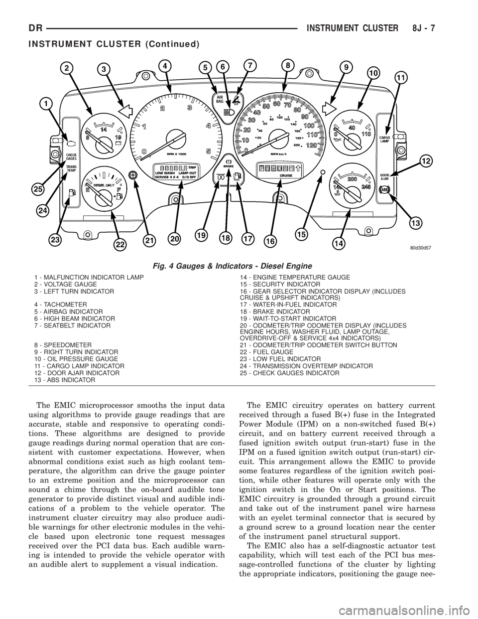
Fig. 4 Gauges & Indicators - Diesel Engine
1 - MALFUNCTION INDICATOR LAMP 14 - ENGINE TEMPERATURE GAUGE
2 - VOLTAGE GAUGE 15 - SECURITY INDICATOR
3 - LEFT TURN INDICATOR 16 - GEAR SELECTOR INDICATOR DISPLAY (INCLUDES
CRUISE & UPSHIFT INDICATORS)
4 - TACHOMETER 17 - WATER-IN-FUEL INDICATOR
5 - AIRBAG INDICATOR 18 - BRAKE INDICATOR
6 - HIGH BEAM INDICATOR 19 - WAIT-TO-START INDICATOR
7 - SEATBELT INDICATOR 20 - ODOMETER/TRIP ODOMETER DISPLAY (INCLUDES
ENGINE HOURS, WASHER FLUID, LAMP OUTAGE,
OVERDRIVE-OFF & SERVICE 4x4 INDICATORS)
8 - SPEEDOMETER 21 - ODOMETER/TRIP ODOMETER SWITCH BUTTON
9 - RIGHT TURN INDICATOR 22 - FUEL GAUGE
10 - OIL PRESSURE GAUGE 23 - LOW FUEL INDICATOR
11 - CARGO LAMP INDICATOR 24 - TRANSMISSION OVERTEMP INDICATOR
12 - DOOR AJAR INDICATOR 25 - CHECK GAUGES INDICATOR
13 - ABS INDICATOR
DRINSTRUMENT CLUSTER 8J - 7
INSTRUMENT CLUSTER (Continued)
Page 531 of 2895

onds, the gauge needle will return to the left end of
the gauge scale.
²Actuator Test- Each time the cluster is put
through the actuator test, the tachometer needle will
be swept to several calibration points on the gauge
scale in a prescribed sequence in order to confirm the
functionality of the gauge and the cluster control cir-
cuitry.
On vehicles with a gasoline engine, the PCM con-
tinually monitors the crankshaft position sensor to
determine the engine speed. On vehicles with a die-
sel engine, the ECM continually monitors the engine
speed sensor to determine the engine speed. The
PCM or ECM then sends the proper engine speed
messages to the instrument cluster. For further diag-
nosis of the tachometer or the instrument cluster cir-
cuitry that controls the gauge, (Refer to 8 -
ELECTRICAL/INSTRUMENT CLUSTER - DIAGNO-
SIS AND TESTING). For proper diagnosis of the
crankshaft position sensor, the engine speed sensor,
the PCM, the ECM, the PCI data bus, or the elec-
tronic message inputs to the instrument cluster that
control the tachometer, a DRBIIItscan tool is
required. Refer to the appropriate diagnostic infor-
mation.
TRANS TEMP INDICATOR
DESCRIPTION
A transmission over-temperature indicator is stan-
dard equipment on all instrument clusters. However,
on vehicles not equipped with an optional automatic
transmission, this indicator is electronically disabled.
The transmission over-temperature indicator is
located on the left side of the instrument cluster, to
the left of the fuel gauge. The transmission over-tem-
perature indicator consists of a stencil-like cutout of
the words ªTRANS TEMPº in the opaque layer of the
instrument cluster overlay. The dark outer layer of
the overlay prevents the indicator from being clearly
visible when it is not illuminated. A red Light Emit-
ting Diode (LED) behind the cutout in the opaque
layer of the overlay causes the ªTRANS TEMPº text
to appear in red through the translucent outer layer
of the overlay when the indicator is illuminated from
behind by the LED, which is soldered onto the
instrument cluster electronic circuit board. The
transmission over-temperature indicator is serviced
as a unit with the instrument cluster.
OPERATION
The transmission over-temperature indicator gives
an indication to the vehicle operator when the trans-
mission fluid temperature is excessive, which may
lead to accelerated transmission component wear orfailure. This indicator is controlled by a transistor on
the instrument cluster circuit board based upon clus-
ter programming and electronic messages received by
the cluster from the Powertrain Control Module
(PCM) over the Programmable Communications
Interface (PCI) data bus. The transmission over-tem-
perature indicator Light Emitting Diode (LED) is
completely controlled by the instrument cluster logic
circuit, and that logic will only allow this indicator to
operate when the instrument cluster receives a bat-
tery current input on the fused ignition switch out-
put (run-start) circuit. Therefore, the LED will
always be off when the ignition switch is in any posi-
tion except On or Start. The LED only illuminates
when it is provided a path to ground by the instru-
ment cluster transistor. The instrument cluster will
turn on the transmission over-temperature indicator
for the following reasons:
²Bulb Test- Each time the ignition switch is
turned to the On position the transmission over-tem-
perature indicator is illuminated for about two sec-
onds as a bulb test.
²Trans Over-Temp Lamp-On Message- Each
time the cluster receives a trans over-temp lamp-on
message from the PCM indicating that the transmis-
sion fluid temperature is 135É C (275É F) or higher,
the indicator will be illuminated and a single chime
tone is sounded. The indicator remains illuminated
until the cluster receives a trans over-temp lamp-off
message from the PCM, or until the ignition switch
is turned to the Off position, whichever occurs first.
The chime tone feature will only repeat during the
same ignition cycle if the transmission over-tempera-
ture indicator is cycled off and then on again by the
appropriate trans over-temp messages from the PCM.
²Actuator Test- Each time the cluster is put
through the actuator test, the transmission over-tem-
perature indicator will be turned on, then off again
during the bulb check portion of the test to confirm
the functionality of the LED and the cluster control
circuitry.
The PCM continually monitors the transmission
temperature sensor to determine the transmission
operating condition. The PCM then sends the proper
trans over-temp lamp-on or lamp-off messages to the
instrument cluster. If the instrument cluster turns on
the transmission over-temperature indicator due to a
high transmission oil temperature condition, it may
indicate that the transmission and/or the transmis-
sion cooling system are being overloaded or that they
require service. For further diagnosis of the trans-
mission over-temperature indicator or the instrument
cluster circuitry that controls the LED, (Refer to 8 -
ELECTRICAL/INSTRUMENT CLUSTER - DIAGNO-
SIS AND TESTING). For proper diagnosis of the
transmission temperature sensor, the PCM, the PCI
8J - 38 INSTRUMENT CLUSTERDR
TACHOMETER (Continued)
Page 1435 of 2895
STANDARD PROCEDURE
STANDARD PROCEDURE - REPAIR DAMAGED
OR WORN THREADS
CAUTION: Be sure that the tapped holes maintain
the original center line.
Damaged or worn threads can be repaired. Essen-
tially, this repair consists of:
²Drilling out worn or damaged threads.
²Tapping the hole with a special Heli-Coil Tap, or
equivalent.
²Installing an insert into the tapped hole to bring
the hole back to its original thread size.
STANDARD PROCEDUREÐHYDROSTATIC
LOCK
CAUTION: DO NOT use the starter motor to rotate
the crankshaft. Severe damage could occur.
When an engine is suspected of hydrostatic lock
(regardless of what caused the problem), follow the
steps below.
(1) Perform the Fuel Pressure Release Procedure
(Refer to 14 - FUEL SYSTEM/FUEL DELIVERY -
STANDARD PROCEDURE).
(2) Disconnect the negative cable(s) from the bat-
tery.
(3) Inspect air cleaner, induction system, and
intake manifold to ensure system is dry and clear of
foreign material.
(4) Place a shop towel around the spark plugs to
catch any fluid that may possibly be under pressure
in the cylinder head. Remove the spark plugs.
(5) With all spark plugs removed, rotate the crank-
shaft using a breaker bar and socket.
(6) Identify the fluid in the cylinders (coolant, fuel,
oil, etc.).
(7) Be sure all fluid has been removed from the
cylinders.
(8) Repair engine or components as necessary to
prevent this problem from occurring again.
(9) Squirt a small amount of engine oil into the
cylinders to lubricate the walls. This will prevent
damage on restart.
(10) Install new spark plugs. Tighten the spark
plugs to 41 N´m (30 ft. lbs.) torque.
(11) Drain engine oil. Remove and discard the oil
filter.
(12) Install the drain plug. Tighten the plug to 34
N´m (25 ft. lbs.) torque.
(13) Install a new oil filter.(14) Fill engine crankcase with the specified
amount and grade of oil. (Refer to LUBRICATION &
MAINTENANCE - SPECIFICATIONS).
(15) Connect the negative cable(s) to the battery.
(16) Start the engine and check for any leaks.
REMOVAL
(1) Disconnect the battery negative cable.
(2) Remove the air cleaner resonator and duct
work as an assembly.
(3) Drain cooling system (Refer to 7 - COOLING -
STANDARD PROCEDURE).
(4) Remove the accessory drive belt (Refer to 7 -
COOLING/ACCESSORY DRIVE/DRIVE BELTS -
REMOVAL).
(5) Remove the viscous fan/drive (Refer to 7 -
COOLING/ENGINE/RADIATOR FAN - REMOVAL).
(6) Remove radiator (Refer to 7 - COOLING/EN-
GINE/RADIATOR - REMOVAL).
(7) Remove the upper crossmember and top core
support.
NOTE: It is not necessary to drain A/C system for
engine removal.
(8) Remove the A/C compressor with the lines
attached. Secure compressor out of the way.
(9) Remove generator assembly (Refer to 8 -
ELECTRICAL/CHARGING/GENERATOR - REMOV-
AL).
(10) Perform the Fuel System Pressure Release
procedure (Refer to 14 - FUEL SYSTEM/FUEL
DELIVERY - STANDARD PROCEDURE).
(11) Remove the intake manifold and IAFM as an
assembly(Refer to 9 - ENGINE/MANIFOLDS/IN-
TAKE MANIFOLD - REMOVAL).
(12) Disconnect the heater hoses.
NOTE: It is not necessary to disconnect P/S hoses
from pump, for P/S pump removal.
(13) Remove the power steering pump and set
aside.
(14) Disconnect the fuel supply line (Refer to 14 -
FUEL SYSTEM/FUEL DELIVERY/QUICK CON-
NECT FITTING - STANDARD PROCEDURE).
(15) Raise and support the vehicle on a hoist and
drain the engine oil.
(16) Remove engine front mount thru-bolt nuts.
(17) Disconnect the transmission oil cooler lines
from their retainers at the oil pan bolts.
(18) Disconnect exhaust pipe at manifolds.
(19) Disconnect the starter wires. Remove starter
motor (Refer to 8 - ELECTRICAL/STARTING/
STARTER MOTOR - REMOVAL).
9 - 186 ENGINE - 5.7LDR
ENGINE - 5.7L (Continued)
Page 1482 of 2895
(1) Perform the Fuel Pressure Release Procedure
(Refer to 14 - FUEL SYSTEM/FUEL DELIVERY -
STANDARD PROCEDURE).
(2) Disconnect the negative cable(s) from the bat-
tery.
(3) Inspect air cleaner, induction system, and
intake manifold to ensure system is dry and clear of
foreign material.
(4) Place a shop towel around the spark plugs to
catch any fluid that may possibly be under pressure
in the cylinder head. Remove the spark plugs.
(5) With all spark plugs removed, rotate the crank-
shaft using a breaker bar and socket.
(6) Identify the fluid in the cylinders (coolant, fuel,
oil, etc.).
(7) Be sure all fluid has been removed from the
cylinders.
(8) Repair engine or components as necessary to
prevent this problem from occurring again.
(9) Squirt a small amount of engine oil into the
cylinders to lubricate the walls. This will prevent
damage on restart.
(10) Install new spark plugs. Tighten the spark
plugs to 41 N´m (30 ft. lbs.) torque.
(11) Drain engine oil. Remove and discard the oil
filter.
(12) Install the drain plug. Tighten the plug to 34
N´m (25 ft. lbs.) torque.
(13) Install a new oil filter.
(14) Fill engine crankcase with the specified
amount and grade of oil. (Refer to LUBRICATION &
MAINTENANCE - SPECIFICATIONS).
(15) Connect the negative cable(s) to the battery.
(16) Start the engine and check for any leaks.
STANDARD PROCEDURE - CYLINDER BORE
HONING
Before honing, stuff plenty of clean shop towels
under the bores and over the crankshaft to keep
abrasive materials from entering the crankshaft
area.
(1) Used carefully, the Cylinder Bore Sizing Hone
C-823, equipped with 220 grit stones, is the best tool
for this job. In addition to deglazing, it will reduce
taper and out-of-round, as well as removing light
scuffing, scoring and scratches. Usually, a few strokes
will clean up a bore and maintain the required lim-
its.
CAUTION: DO NOT use rigid type hones to remove
cylinder wall glaze.
(2) Deglazing of the cylinder walls may be done if
the cylinder bore is straight and round. Use a cylin-
der surfacing hone, Honing Tool C-3501, equipped
with 280 grit stones (C-3501-3810). about 20-60strokes, depending on the bore condition, will be suf-
ficient to provide a satisfactory surface. Using honing
oil C-3501-3880, or a light honing oil, available from
major oil distributors.
CAUTION: DO NOT use engine or transmission oil,
mineral spirits, or kerosene.
(3) Honing should be done by moving the hone up
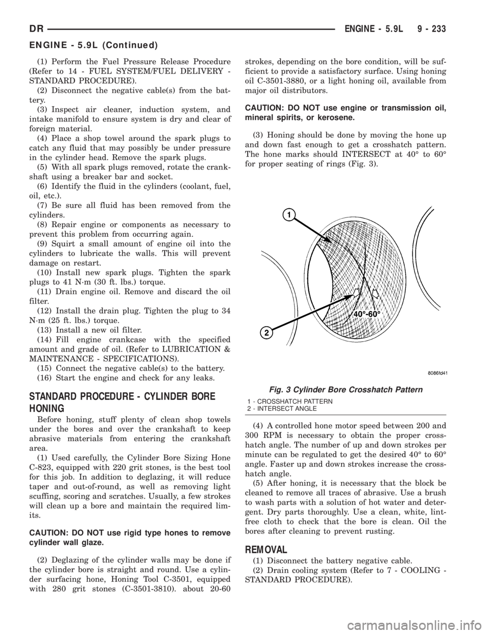
and down fast enough to get a crosshatch pattern.
The hone marks should INTERSECT at 40É to 60É
for proper seating of rings (Fig. 3).
(4) A controlled hone motor speed between 200 and
300 RPM is necessary to obtain the proper cross-
hatch angle. The number of up and down strokes per
minute can be regulated to get the desired 40É to 60É
angle. Faster up and down strokes increase the cross-
hatch angle.
(5) After honing, it is necessary that the block be
cleaned to remove all traces of abrasive. Use a brush
to wash parts with a solution of hot water and deter-
gent. Dry parts thoroughly. Use a clean, white, lint-
free cloth to check that the bore is clean. Oil the
bores after cleaning to prevent rusting.
REMOVAL
(1) Disconnect the battery negative cable.
(2) Drain cooling system (Refer to 7 - COOLING -
STANDARD PROCEDURE).
Fig. 3 Cylinder Bore Crosshatch Pattern
1 - CROSSHATCH PATTERN
2 - INTERSECT ANGLE
DRENGINE - 5.9L 9 - 233
ENGINE - 5.9L (Continued)
Page 1538 of 2895
(9) Use Tool 9010 to remove the injector and cop-
per sealing washer.
(10) Install compression test Tool 9007 into the
injector bore.
(11) Connect the leakage tester and perform the
leakage test procedure on each cylinder according to
the tester manufacturer's instructions.
(12) Upon completion of the test check and erase
any engine related fault codes.
STANDARD PROCEDURE
STANDARD PROCEDURE - FORM-IN-PLACE
GASKETS AND SEALERS
There are numerous places where form-in-place
gaskets are used on the engine. Care must be taken
when applying form-in-place gaskets to assure
obtaining the desired results.Do not use form-in-
place gasket material unless specified.Bead size,
continuity, and location are of great importance. Too
thin a bead can result in leakage while too much can
result in spill-over which can break off and obstruct
fluid feed lines. A continuous bead of the proper
width is essential to obtain a leak-free gasket.
There are numerous types of form-in-place gasket
materials that are used in the engine area. Mopart
Engine RTV GEN II, MopartATF-RTV, and Mopart
Gasket Maker gasket materials, each have different
properties and can not be used in place of the other.
MOPARtENGINE RTV GEN II
MopartEngine RTV GEN II is used to seal com-
ponents exposed to engine oil. This material is a spe-
cially designed black silicone rubber RTV that
retains adhesion and sealing properties when
exposed to engine oil. Moisture in the air causes the
material to cure. This material is available in three
ounce tubes and has a shelf life of one year. After one
year this material will not properly cure. Always
inspect the package for the expiration date before
use.
MOPARtATF RTV
MopartATF RTV is a specifically designed black
silicone rubber RTV that retains adhesion and seal-
ing properties to seal components exposed to auto-
matic transmission fluid, engine coolants, and
moisture. This material is available in three ounce
tubes and has a shelf life of one year. After one year
this material will not properly cure. Always inspect
the package for the expiration date before use.
MOPARtGASKET MAKER
MopartGasket Maker is an anaerobic type gasket
material. The material cures in the absence of air
when squeezed between two metallic surfaces. It will
not cure if left in the uncovered tube. The anaerobicmaterial is for use between two machined surfaces.
Do not use on flexible metal flanges.
MOPARtGASKET SEALANT
MopartGasket Sealant is a slow drying, perma-
nently soft sealer. This material is recommended for
sealing threaded fittings and gaskets against leakage
of oil and coolant. Can be used on threaded and
machined parts under all temperatures. This mate-
rial is used on engines with multi-layer steel (MLS)
cylinder head gaskets. This material also will pre-
vent corrosion. MopartGasket Sealant is available in
a 13 oz. aerosol can or 4oz./16 oz. can w/applicator.
FORM-IN-PLACE GASKET AND SEALER
APPLICATION
Assembling parts using a form-in-place gasket
requires care but it's easier than using precut gas-
kets.
MopartGasket Maker material should be applied
sparingly 1 mm (0.040 in.) diameter or less of sealant
to one gasket surface. Be certain the material sur-
rounds each mounting hole. Excess material can eas-
ily be wiped off. Components should be torqued in
place within 15 minutes. The use of a locating dowel
is recommended during assembly to prevent smear-
ing material off the location.
MopartEngine RTV GEN II or ATF RTV gasket
material should be applied in a continuous bead
approximately 3 mm (0.120 in.) in diameter. All
mounting holes must be circled. For corner sealing, a
3.17 or 6.35 mm (1/8 or 1/4 in.) drop is placed in the
center of the gasket contact area. Uncured sealant
may be removed with a shop towel. Components
should be torqued in place while the sealant is still
wet to the touch (within 10 minutes). The usage of a
locating dowel is recommended during assembly to
prevent smearing material off the location.
MopartGasket Sealant in an aerosol can should be
applied using a thin, even coat sprayed completely
over both surfaces to be joined, and both sides of a
gasket. Then proceed with assembly. Material in a
can w/applicator can be brushed on evenly over the
sealing surfaces. Material in an aerosol can should be
used on engines with multi-layer steel gaskets.
STANDARD PROCEDURE - REPAIR DAMAGED
OR WORN THREADS
CAUTION: Be sure that the tapped holes maintain
the original center line.
Damaged or worn threads can be repaired. Essen-
tially, this repair consists of:
²Drilling out worn or damaged threads.
²Tapping the hole with a special Heli-Coil Tap, or
equivalent.
DRENGINE 5.9L DIESEL 9 - 289
ENGINE 5.9L DIESEL (Continued)
Page 1539 of 2895
²Installing an insert into the tapped hole to bring
the hole back to its original thread size.
STANDARD PROCEDUREÐHYDROSTATIC
LOCK
CAUTION: DO NOT use the starter motor to rotate
the crankshaft. Severe damage could occur.
When an engine is suspected of hydrostatic lock
(regardless of what caused the problem), follow the
steps below.
(1) Disconnect the negative cable(s) from the bat-
tery.
(2) Inspect air cleaner, induction system, and
intake manifold to ensure system is dry and clear of
foreign material.
(3) Place a shop towel around the fuel injectors to
catch any fluid that may possibly be under pressure
in the cylinder head. Remove the fuel injectors (Refer
to 14 - FUEL SYSTEM/FUEL INJECTION/FUEL
INJECTOR - REMOVAL).
(4) With all injectors removed, rotate the crank-
shaft using the crankshaft barring tool (PN 7471±B).
(5) Identify the fluid in the cylinders (coolant, fuel,
oil, etc.).
(6) Be sure all fluid has been removed from the
cylinders.
(7) Repair engine or components as necessary to
prevent this problem from occurring again.
(8) Squirt a small amount of engine oil into the
cylinders to lubricate the walls. This will prevent
damage on restart.
(9) Install fuel injectors (Refer to 14 - FUEL SYS-
TEM/FUEL INJECTION/FUEL INJECTOR -
INSTALLATION).
(10) Drain engine oil. Remove and discard the oil
filter (Refer to 9 - ENGINE/LUBRICATION/OIL FIL-
TER - REMOVAL).
(11) Install the drain plug. Tighten the plug to 50
N´m (37 ft. lbs.) torque.
(12) Install a new oil filter (Refer to 9 - ENGINE/
LUBRICATION/OIL FILTER - INSTALLATION).
(13) Fill engine crankcase with the specified
amount and grade of oil (Refer to LUBRICATION &
MAINTENANCE/FLUID TYPES - SPECIFICA-
TIONS).
(14) Connect the negative cable(s) to the battery.
(15) Start the engine and check for any leaks.
REMOVAL
REMOVALÐENGINE
(1) Disconnect both battery negative cables.
(2) Disconnect engine grid heater harness at grid
heater relays.(3) Disconnect electrical connections from rear of
alternator.
(4) Recover A/C refrigerant. (Refer to 24 - HEAT-
ING & AIR CONDITIONING/PLUMBING - STAN-
DARD PROCEDURE).
(5) Raise vehicle on a hoist.
(6) Drain engine coolant (Refer to 7 - COOLING -
STANDARD PROCEDURE).
(7) Remove engine oil drain plug and drain engine
oil.
(8) Remove fan/drive assembly. Refer to Section 7
± Fan/Drive Removal
(9) Remove radiator upper hose.
(10) Remove upper fan shroud mounting bolts.
(11) Disconnect the coolant recovery bottle hose
from the radiator fill neck and remove bottle.
(12) Using a 36mm wrench, remove viscous fan/
drive assembly. (Refer to 7 - COOLING/ENGINE/RA-
DIATOR FAN - REMOVAL).
(13) Remove cooling fan and shroud together.
(14) Disconnect heater core supply and return
hoses from the cylinder head fitting and coolant pipe.
(15) Raise vehicle on a hoist.
(16) Remove transmission and transfer case (if
equipped).
(17) Disconnect exhaust pipe from turbocharger
extension pipe.
(18) Disconnect engine harness to vehicle harness
connectors.
(19) Remove starter motor (Refer to 8 - ELECTRI-
CAL/STARTING/STARTER MOTOR - REMOVAL).
(20) Remove flywheel/flexplate.
(21) Remove transmission adapter
(22) Disconnect A/C suction/discharge hose from
the rear of the A/C compressor.
(23) Lower vehicle.
(24) Disconnect lower radiator hose from radiator
outlet.
(25) Automatic transmission models:
(26) Disconnect transmission oil cooler lines from
in front of radiator using special tool #6931
(27) Remove radiator. (Refer to 7 - COOLING/EN-
GINE/RADIATOR - REMOVAL).
(28) If A/C equipped, disconnect A/C condenser
refrigerant lines.
(29) Disconnect charge air cooler piping.
(30) Remove charge air cooler mounting bolts.
(31) Remove charge air cooler (and A/C condenser
if equipped) from vehicle.
(32) Remove damper and speed indicator ring from
front of engine.
(33) Disconnect engine block heater connector.
(34) Disconnect A/C compressor and pressure sen-
sor electrical connectors.
9 - 290 ENGINE 5.9L DIESELDR
ENGINE 5.9L DIESEL (Continued)
Page 1570 of 2895
(14) Install the fan support/hub assembly and
tighten bolts to 33 N´m (24 ft. lbs.) torque.
(15) Install the power steering pump.
(16) Install accessory drive belt tensioner. Torque
bolt to 43 Nm (43 ft. lbs.).
(17) Install the accessory drive belt (Refer to 7 -
COOLING/ACCESSORY DRIVE/DRIVE BELTS -
INSTALLATION).
(18) Install the charge air cooler (with a/c con-
denser and auxiliary transmission oil cooler, if
equipped) and tighten the mounting bolts to 2 N´m
(17 in. lbs.) torque.
(19) Connect charge air cooler inlet and outlet
pipes. Tighten clamps to 11 N´m (95 in. lbs.) torque.
(20) Install the radiator upper support panel.
(21) Close radiator petcock and lower the radiator
into the engine compartment. Tighten the mounting
bolts to 11 N´m (95 in. lbs.) torque.
(22) Raise vehicle on hoist.
(23)
Connect radiator lower hose and install clamp.
(24) Connect transmission auxiliary oil cooler lines
(if equipped).
(25) Lower vehicle.
(26) Install the fan shroud and tighten the mount-
ing screws to 6 N´m (50 in. lbs.) torque.
(27) Install the electronically controlled viscous
fan/drive assembly. Connect harness connector.(Refer
to 7 - COOLING/ENGINE/RADIATOR FAN -
INSTALLATION).
(28) Install the coolant recovery and windshield
washer fluid reservoirs to the fan shroud.
(29) Connect the coolant recovery hose to the radi-
ator filler neck.
(30) Add engine coolant (Refer to 7 - COOLING -
STANDARD PROCEDURE).
(31) Charge A/C system with refrigerant (if A/C
equipped) (Refer to 24 - HEATING & AIR CONDI-
TIONING/PLUMBING - STANDARD PROCEDURE).
(32) Connect the battery negative cables.
(33) Start engine and check for engine oil and cool-
ant leaks.
CONNECTING ROD BEARINGS
STANDARD PROCEDURE - CONNECTING ROD
BEARING AND CRANKSHAFT JOURNAL
CLEARANCE
(1) Measure the connecting rod bore with bearings
removedand the bolts tightened to 100 N´m (73 ft.
lbs.) torque..
(2) Measure the connecting rod bore with the bear-
ingsinstalledand the bolts tightened to 100 N´m
(73 ft. lbs.) torque.
Measure within 20É arc from each side of the part-
ing line. Also measure 90É from parting line.Record the smallest and largest diameter.
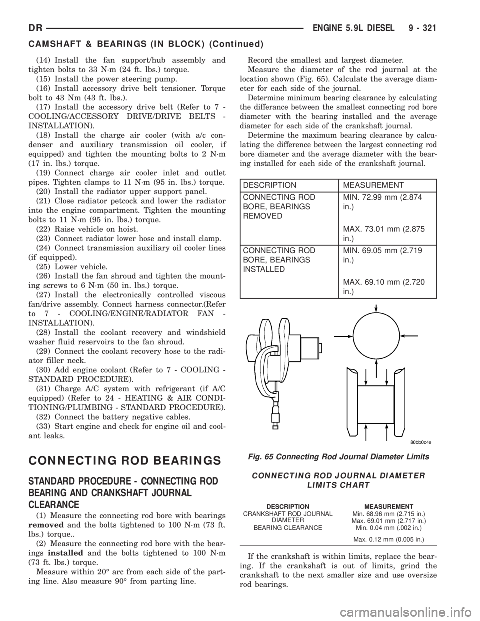
Measure the diameter of the rod journal at the
location shown (Fig. 65). Calculate the average diam-
eter for each side of the journal.
Determine minimum bearing clearance by calculating
the differance between the smallest connecting rod bore
diameter with the bearing installed and the average
diameter for each side of the crankshaft journal.
Determine the maximum bearing clearance by calcu-
lating the difference between the largest connecting rod
bore diameter and the average diameter with the bear-
ing installed for each side of the crankshaft journal.
DESCRIPTION MEASUREMENT
CONNECTING ROD
BORE, BEARINGS
REMOVEDMIN. 72.99 mm (2.874
in.)
MAX. 73.01 mm (2.875
in.)
CONNECTING ROD
BORE, BEARINGS
INSTALLEDMIN. 69.05 mm (2.719
in.)
MAX. 69.10 mm (2.720
in.)
If the crankshaft is within limits, replace the bear-
ing. If the crankshaft is out of limits, grind the
crankshaft to the next smaller size and use oversize
rod bearings.
Fig. 65 Connecting Rod Journal Diameter Limits
CONNECTING ROD JOURNAL DIAMETER
LIMITS CHART
DESCRIPTION MEASUREMENT
CRANKSHAFT ROD JOURNAL
DIAMETERMin. 68.96 mm (2.715 in.)
Max. 69.01 mm (2.717 in.)
BEARING CLEARANCE Min. 0.04 mm (.002 in.)
Max. 0.12 mm (0.005 in.)
DRENGINE 5.9L DIESEL 9 - 321
CAMSHAFT & BEARINGS (IN BLOCK) (Continued)