2003 DODGE RAM Trans cooler diesel
[x] Cancel search: Trans cooler dieselPage 1570 of 2895
(14) Install the fan support/hub assembly and
tighten bolts to 33 N´m (24 ft. lbs.) torque.
(15) Install the power steering pump.
(16) Install accessory drive belt tensioner. Torque
bolt to 43 Nm (43 ft. lbs.).
(17) Install the accessory drive belt (Refer to 7 -
COOLING/ACCESSORY DRIVE/DRIVE BELTS -
INSTALLATION).
(18) Install the charge air cooler (with a/c con-
denser and auxiliary transmission oil cooler, if
equipped) and tighten the mounting bolts to 2 N´m
(17 in. lbs.) torque.
(19) Connect charge air cooler inlet and outlet
pipes. Tighten clamps to 11 N´m (95 in. lbs.) torque.
(20) Install the radiator upper support panel.
(21) Close radiator petcock and lower the radiator
into the engine compartment. Tighten the mounting
bolts to 11 N´m (95 in. lbs.) torque.
(22) Raise vehicle on hoist.
(23)
Connect radiator lower hose and install clamp.
(24) Connect transmission auxiliary oil cooler lines
(if equipped).
(25) Lower vehicle.
(26) Install the fan shroud and tighten the mount-
ing screws to 6 N´m (50 in. lbs.) torque.
(27) Install the electronically controlled viscous
fan/drive assembly. Connect harness connector.(Refer
to 7 - COOLING/ENGINE/RADIATOR FAN -
INSTALLATION).
(28) Install the coolant recovery and windshield
washer fluid reservoirs to the fan shroud.
(29) Connect the coolant recovery hose to the radi-
ator filler neck.
(30) Add engine coolant (Refer to 7 - COOLING -
STANDARD PROCEDURE).
(31) Charge A/C system with refrigerant (if A/C
equipped) (Refer to 24 - HEATING & AIR CONDI-
TIONING/PLUMBING - STANDARD PROCEDURE).
(32) Connect the battery negative cables.
(33) Start engine and check for engine oil and cool-
ant leaks.
CONNECTING ROD BEARINGS
STANDARD PROCEDURE - CONNECTING ROD
BEARING AND CRANKSHAFT JOURNAL
CLEARANCE
(1) Measure the connecting rod bore with bearings
removedand the bolts tightened to 100 N´m (73 ft.
lbs.) torque..
(2) Measure the connecting rod bore with the bear-
ingsinstalledand the bolts tightened to 100 N´m
(73 ft. lbs.) torque.
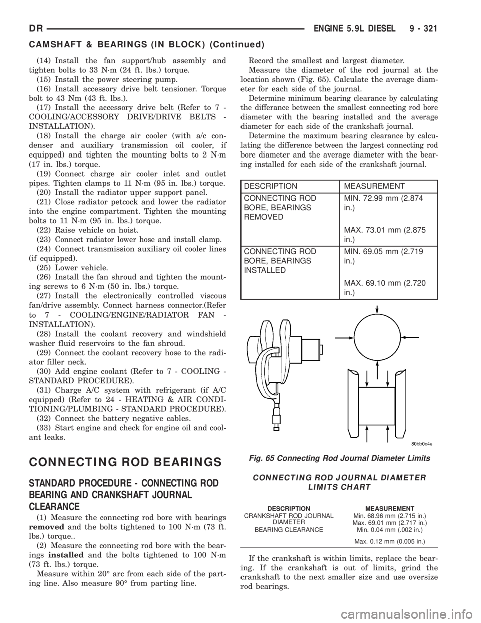
Measure within 20É arc from each side of the part-
ing line. Also measure 90É from parting line.Record the smallest and largest diameter.
Measure the diameter of the rod journal at the
location shown (Fig. 65). Calculate the average diam-
eter for each side of the journal.
Determine minimum bearing clearance by calculating
the differance between the smallest connecting rod bore
diameter with the bearing installed and the average
diameter for each side of the crankshaft journal.
Determine the maximum bearing clearance by calcu-
lating the difference between the largest connecting rod
bore diameter and the average diameter with the bear-
ing installed for each side of the crankshaft journal.
DESCRIPTION MEASUREMENT
CONNECTING ROD
BORE, BEARINGS
REMOVEDMIN. 72.99 mm (2.874
in.)
MAX. 73.01 mm (2.875
in.)
CONNECTING ROD
BORE, BEARINGS
INSTALLEDMIN. 69.05 mm (2.719
in.)
MAX. 69.10 mm (2.720
in.)
If the crankshaft is within limits, replace the bear-
ing. If the crankshaft is out of limits, grind the
crankshaft to the next smaller size and use oversize
rod bearings.
Fig. 65 Connecting Rod Journal Diameter Limits
CONNECTING ROD JOURNAL DIAMETER
LIMITS CHART
DESCRIPTION MEASUREMENT
CRANKSHAFT ROD JOURNAL
DIAMETERMin. 68.96 mm (2.715 in.)
Max. 69.01 mm (2.717 in.)
BEARING CLEARANCE Min. 0.04 mm (.002 in.)
Max. 0.12 mm (0.005 in.)
DRENGINE 5.9L DIESEL 9 - 321
CAMSHAFT & BEARINGS (IN BLOCK) (Continued)
Page 1586 of 2895
REAR MOUNT
REMOVAL
(1) Raise the vehicle on a hoist.
(2) Position a transmission jack in place.
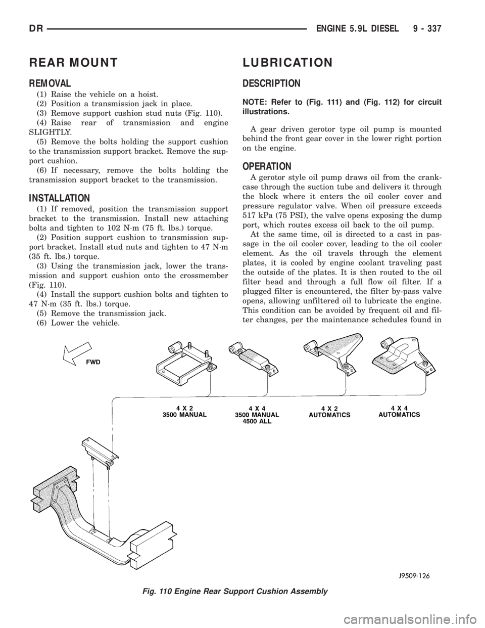
(3) Remove support cushion stud nuts (Fig. 110).
(4) Raise rear of transmission and engine
SLIGHTLY.
(5) Remove the bolts holding the support cushion
to the transmission support bracket. Remove the sup-
port cushion.
(6) If necessary, remove the bolts holding the
transmission support bracket to the transmission.
INSTALLATION
(1) If removed, position the transmission support
bracket to the transmission. Install new attaching
bolts and tighten to 102 N´m (75 ft. lbs.) torque.
(2) Position support cushion to transmission sup-
port bracket. Install stud nuts and tighten to 47 N´m
(35 ft. lbs.) torque.
(3) Using the transmission jack, lower the trans-
mission and support cushion onto the crossmember
(Fig. 110).
(4) Install the support cushion bolts and tighten to
47 N´m (35 ft. lbs.) torque.
(5) Remove the transmission jack.
(6) Lower the vehicle.
LUBRICATION
DESCRIPTION
NOTE: Refer to (Fig. 111) and (Fig. 112) for circuit
illustrations.
A gear driven gerotor type oil pump is mounted
behind the front gear cover in the lower right portion
on the engine.
OPERATION
A gerotor style oil pump draws oil from the crank-
case through the suction tube and delivers it through
the block where it enters the oil cooler cover and
pressure regulator valve. When oil pressure exceeds
517 kPa (75 PSI), the valve opens exposing the dump
port, which routes excess oil back to the oil pump.
At the same time, oil is directed to a cast in pas-
sage in the oil cooler cover, leading to the oil cooler
element. As the oil travels through the element
plates, it is cooled by engine coolant traveling past
the outside of the plates. It is then routed to the oil
filter head and through a full flow oil filter. If a
plugged filter is encountered, the filter by-pass valve
opens, allowing unfiltered oil to lubricate the engine.
This condition can be avoided by frequent oil and fil-
ter changes, per the maintenance schedules found in
Fig. 110 Engine Rear Support Cushion Assembly
DRENGINE 5.9L DIESEL 9 - 337
Page 1591 of 2895
OIL COOLER & LINES
CLEANING
CLEANING AND INSPECTION
Clean the sealing surfaces.
Apply 483 kPa (70 psi) air pressure to the element
to check for leaks. If the element leaks, replace the
element.
OIL FILTER
REMOVAL
(1) Clean the area around the oil filter head.
Remove the filter from below using a cap-style filter
wrench.
(2) Clean the gasket surface of the filter head. The
filter canister O-Ring seal can stick on the filter
head. Make sure it is removed.
INSTALLATION
(1) Fill the oil filter element with clean oil before
installation. Use the same type oil that will be used
in the engine.
(2) Apply a light film of lubricating oil to the seal-
ing surface before installing the filter.
CAUTION: Mechanical over-tightening may distort
the threads or damage the filter element seal.
(3) Install the filter until it contacts the sealing
surface of the oil filter adapter. Tighten filter an
additional
1¤2turn.
OIL PAN
REMOVAL
(1) Disconnect the battery negative cables.
(2) Install engine support fixture # 8534.
(3) Raise vehicle on hoist.
(4) Disconnect starter cables from starter motor.
(5) Remove starter motor (Refer to 8 - ELECTRI-
CAL/STARTING/STARTER MOTOR - REMOVAL)
and transmission adapter plate assembly.
(6) Remove transmission and transfer case (if
equipped).
(7) Remove flywheel or flexplate.
(8) Remove the transmission adapter plate.
WARNING: HOT OIL CAN CAUSE PERSONAL
INJURY.
(9) Drain the engine oil (Refer to 9 - ENGINE/LU-
BRICATION/OIL - STANDARD PROCEDURE).(10) Install the oil pan drain plug if sealing sur-
face is not damaged and tighten to 50 N´m (57 ft.
lbs.) torque.
(11) Remove oil pan bolts, break the pan to block
seal, and lower pan slightly and remove oil suction
tube fasteners.
(12) Remove oil pan and suction tube.
CLEANING
Remove all gasket material from the oil pan and
cylinder block sealing surfaces. Extra effort may be
required around T-joint areas. Clean oil pan and
flush suction tube with a suitable solvent.
INSPECTION
Inspect the oil pan, suction tube, and tube braces
for cracks and damage. Replace any defective compo-
nent. Inspect the oil drain plug and drain hole
threads. Inspect the oil pan sealing surface for
straightness. Repair any minor imperfections with a
ball-peen hammer. Do not attempt to repair an oil
pan by welding.
INSTALLATION
(1) Fill the T-joint between the pan rail/gear hous-
ing and pan rail/rear seal retainer with sealant. Use
MopartSilicone Rubber Adhesive Sealant or equiva-
lent.
(2) Place suction tube in oil pan and guide them
into place. Using a new tube to block gasket, install
and tighten the suction tube bolts by hand. Starting
with the oil pump inlet bolts, tighten the bolts to 24
N´m (18 ft. lbs.) torque. Tighten the remaining tube
brace bolts to 43 N´m (32 ft. lbs.) torque.
(3) Starting in the center and working outward,
tighten the oil pan bolts to 28 N´m (21 ft. lbs.)
torque.
(4) Install the flywheel housing assembly with the
starter motor attached and tighten bolts to 77 N´m
(57 ft. lbs.) torque.
(5) Connect starter motor cables.
(6) Install the flywheel or flexplate. Torque to 137
N´m (101 ft. lbs.).
(7) Install transmission and transfer case (if
equipped).
(8) Lower vehicle.
(9) Remove the engine support fixture # 8534.
(10) Install battery negative cables.
(11) Fill the crankcase with new engine oil.
(12) Start engine and check for leaks. Stop engine,
check oil level, and adjust, if necessary.
9 - 342 ENGINE 5.9L DIESELDR
Page 1831 of 2895
PUMP
TABLE OF CONTENTS
page page
PUMP
DESCRIPTION.........................38
OPERATION...........................38
DIAGNOSIS AND TESTING - PUMP LEAKAGE . 39
STANDARD PROCEDURE
STANDARD PROCEDURE - POWER
STEERING PUMP - INITIAL OPERATION....39
STANDARD PROCEDURE - FLUSHING
POWER STEERING SYSTEM............39
REMOVAL
REMOVAL - GAS......................40
REMOVAL - DIESEL...................40
INSTALLATION
INSTALLATION - GAS..................41
INSTALLATION - DIESEL................41
SPECIFICATIONS
TORQUE CHART......................41
FLUID
DESCRIPTION.........................42
STANDARD PROCEDURE - POWER
STEERING FLUID LEVEL CHECKING......42
FLUID COOLER
REMOVAL.............................42
INSTALLATION.........................42
HOSES - I.F.S.
REMOVAL
REMOVAL - RETURN HOSE - GEAR TO
COOLER............................43
REMOVAL - PRESSURE HOSE...........43
REMOVAL - RETURN HOSE - RESERVOIR
TO COOLER.........................43INSTALLATION
INSTALLATION - RETURN HOSE - GEAR TO
COOLER............................43
INSTALLATION - PRESSURE HOSE.......43
INSTALLATION - RETURN HOSE -
RESERVOIR TO COOLER...............43
HOSES - LINK/COIL
REMOVAL
REMOVAL - RETURN HOSE - GEAR TO
COOLER............................43
REMOVAL - PRESSURE HOSE...........44
REMOVAL - RETURN HOSE - RESERVOIR
TO COOLER.........................44
INSTALLATION
INSTALLATION - RETURN HOSE - GEAR TO
COOLER............................44
INSTALLATION - PRESSURE HOSE.......44
INSTALLATION - RETURN HOSE -
RESERVOIR TO COOLER...............44
POWER STEERING PRESSURE SWITCH
DESCRIPTION.........................45
OPERATION...........................45
REMOVAL - 3.7L, 4.7L & 5.7L..............45
INSTALLATION - 3.7L, 4.7L & 5.7L..........45
PULLEY
REMOVAL.............................45
INSTALLATION.........................46
RESERVOIR
REMOVAL.............................46
INSTALLATION.........................46
PUMP
DESCRIPTION
CAUTION: MOPARTATF+4 is to be used in the
power steering system. No other power steering or
automatic transmission fluid is to be used in the
system. Damage may result to the power steering
pump and system if any other fluid is used, and do
not overfill.
The pump is connected to the steering gear via the
pressure hose and the return hose. The pump shaft
has a pressed-on pulley that is belt driven by the
crankshaft pulley.All vehicles are equipped with a power steering
fluid cooler.
NOTE: Power steering pumps are not interchange-
able with pumps installed on other vehicles.
OPERATION
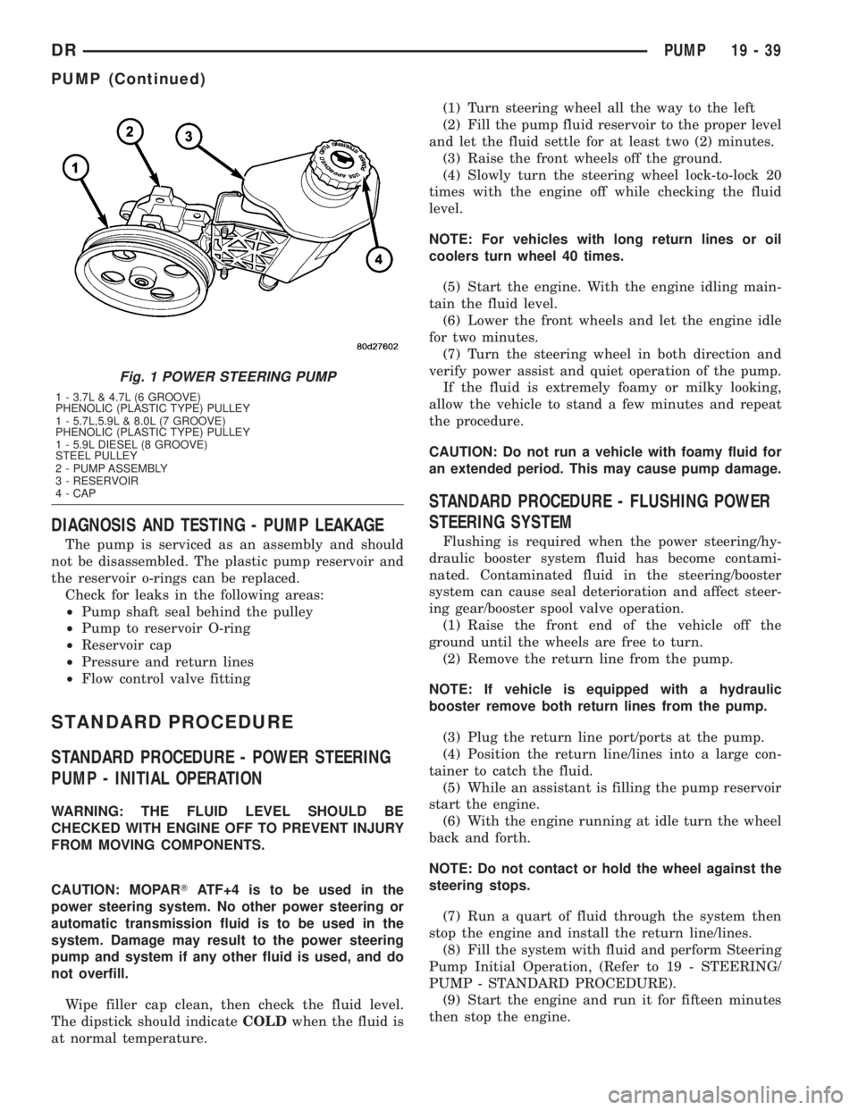
Hydraulic pressure is provided for the power steer-
ing gear by the belt driven power steering pump (Fig.
1). The power steering pumps are constant flow rate
and displacement, vane-type pumps.
19 - 38 PUMPDR
Page 1832 of 2895
DIAGNOSIS AND TESTING - PUMP LEAKAGE
The pump is serviced as an assembly and should
not be disassembled. The plastic pump reservoir and
the reservoir o-rings can be replaced.
Check for leaks in the following areas:
²Pump shaft seal behind the pulley
²Pump to reservoir O-ring
²Reservoir cap
²Pressure and return lines
²Flow control valve fitting
STANDARD PROCEDURE
STANDARD PROCEDURE - POWER STEERING
PUMP - INITIAL OPERATION
WARNING: THE FLUID LEVEL SHOULD BE
CHECKED WITH ENGINE OFF TO PREVENT INJURY
FROM MOVING COMPONENTS.
CAUTION: MOPARTATF+4 is to be used in the
power steering system. No other power steering or
automatic transmission fluid is to be used in the
system. Damage may result to the power steering
pump and system if any other fluid is used, and do
not overfill.
Wipe filler cap clean, then check the fluid level.
The dipstick should indicateCOLDwhen the fluid is
at normal temperature.(1) Turn steering wheel all the way to the left
(2) Fill the pump fluid reservoir to the proper level
and let the fluid settle for at least two (2) minutes.
(3) Raise the front wheels off the ground.
(4) Slowly turn the steering wheel lock-to-lock 20
times with the engine off while checking the fluid
level.
NOTE: For vehicles with long return lines or oil
coolers turn wheel 40 times.
(5) Start the engine. With the engine idling main-
tain the fluid level.
(6) Lower the front wheels and let the engine idle
for two minutes.
(7) Turn the steering wheel in both direction and
verify power assist and quiet operation of the pump.
If the fluid is extremely foamy or milky looking,
allow the vehicle to stand a few minutes and repeat
the procedure.
CAUTION: Do not run a vehicle with foamy fluid for
an extended period. This may cause pump damage.
STANDARD PROCEDURE - FLUSHING POWER
STEERING SYSTEM
Flushing is required when the power steering/hy-
draulic booster system fluid has become contami-
nated. Contaminated fluid in the steering/booster
system can cause seal deterioration and affect steer-
ing gear/booster spool valve operation.
(1) Raise the front end of the vehicle off the
ground until the wheels are free to turn.
(2) Remove the return line from the pump.
NOTE: If vehicle is equipped with a hydraulic
booster remove both return lines from the pump.
(3) Plug the return line port/ports at the pump.
(4) Position the return line/lines into a large con-
tainer to catch the fluid.
(5) While an assistant is filling the pump reservoir
start the engine.
(6) With the engine running at idle turn the wheel
back and forth.
NOTE: Do not contact or hold the wheel against the
steering stops.
(7) Run a quart of fluid through the system then
stop the engine and install the return line/lines.
(8) Fill the system with fluid and perform Steering
Pump Initial Operation, (Refer to 19 - STEERING/
PUMP - STANDARD PROCEDURE).
(9) Start the engine and run it for fifteen minutes
then stop the engine.
Fig. 1 POWER STEERING PUMP
1 - 3.7L & 4.7L (6 GROOVE)
PHENOLIC (PLASTIC TYPE) PULLEY
1 - 5.7L,5.9L & 8.0L (7 GROOVE)
PHENOLIC (PLASTIC TYPE) PULLEY
1 - 5.9L DIESEL (8 GROOVE)
STEEL PULLEY
2 - PUMP ASSEMBLY
3 - RESERVOIR
4 - CAP
DRPUMP 19 - 39
PUMP (Continued)
Page 1835 of 2895
FLUID
DESCRIPTION
The recommended fluid for the power steering sys-
tem is MopartATF +4.
MopartATF+4, when new is red in color. The
ATF+4 is dyed red so it can be identified from other
fluids used in the vehicle such as engine oil or anti-
freeze. The red color is not permanent and is not an
indicator of fluid condition, As the vehicle is driven,
the ATF+4 will begin to look darker in color and may
eventually become brown.THIS IS NORMAL.
ATF+4 also has a unique odor that may change with
age. Consequently, odor and color cannot be used to
indicate the fluid condition or the need for a fluid
change.
STANDARD PROCEDURE - POWER STEERING
FLUID LEVEL CHECKING
WARNING: FLUID LEVEL SHOULD BE CHECKED
WITH THE ENGINE OFF TO PREVENT PERSONAL
INJURY FROM MOVING PARTS.
CAUTION: MOPARTATF+4 is to be used in the
power steering system. No other power steering or
automatic transmission fluid is to be used in the
system. Damage may result to the power steering
pump and system if any other fluid is used, and do
not overfill.
The power steering fluid level can be viewed on the
dipstick attached to the filler cap. There are two
ranges listed on the dipstick, COLD and HOT. Before
opening power steering system, wipe the reservoir
filler cap free of dirt and debris. Remove the cap and
check the fluid level on its dipstick. When the fluid is
at normal ambient temperature, approximately 21ÉC
to 27ÉC (70ÉF to 80ÉF), the fluid level should read
between the minimum and maximum area of the cold
range. When the fluid is hot, fluid level is allowed to
read up to the highest end of the HOT range. Only
add fluid when the vehicle is cold.
Use only MopartATF+4Do not overfill the
power steering system.
FLUID COOLER
REMOVAL
(1) Drain and siphon the power steering fluid.
(2) Disconnect the return and supply hoses con-
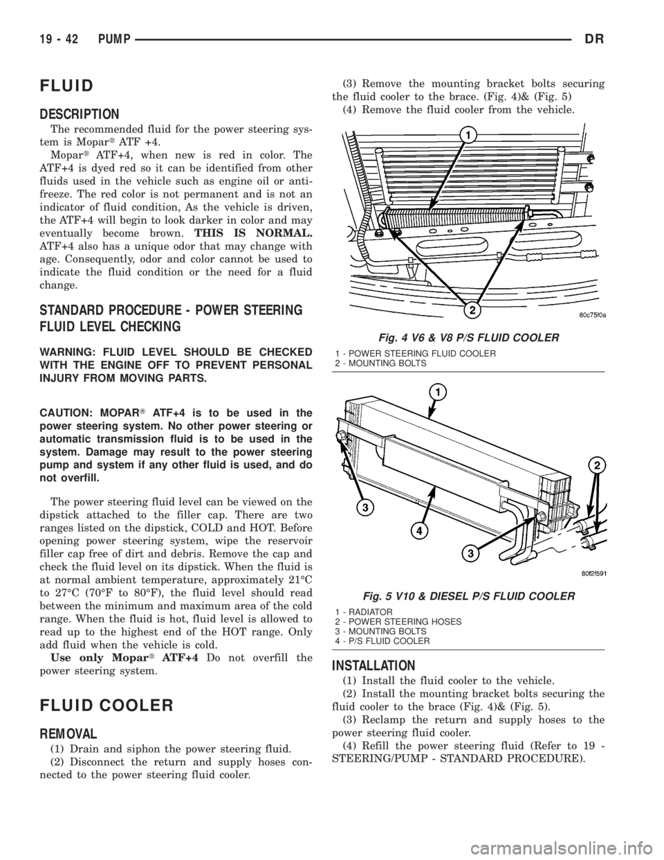
nected to the power steering fluid cooler.(3) Remove the mounting bracket bolts securing
the fluid cooler to the brace. (Fig. 4)& (Fig. 5)
(4) Remove the fluid cooler from the vehicle.
INSTALLATION
(1) Install the fluid cooler to the vehicle.
(2) Install the mounting bracket bolts securing the
fluid cooler to the brace (Fig. 4)& (Fig. 5).
(3) Reclamp the return and supply hoses to the
power steering fluid cooler.
(4) Refill the power steering fluid (Refer to 19 -
STEERING/PUMP - STANDARD PROCEDURE).
Fig. 4 V6 & V8 P/S FLUID COOLER
1 - POWER STEERING FLUID COOLER
2 - MOUNTING BOLTS
Fig. 5 V10 & DIESEL P/S FLUID COOLER
1 - RADIATOR
2 - POWER STEERING HOSES
3 - MOUNTING BOLTS
4 - P/S FLUID COOLER
19 - 42 PUMPDR
Page 2864 of 2895
COOLER - 5.9L DIESEL - DESCRIPTION,
TRANS..............................7-73
COOLER - 5.9L DIESEL - OPERATION,
TRANS..............................7-74
COOLER - INSTALLATION, AIR TO OIL.....7-75
COOLER - INSTALLATION, FLUID........19-42
COOLER - INSTALLATION, RETURN
HOSE - GEAR TO................19-43,19-44
COOLER - INSTALLATION, RETURN
HOSE - RESERVOIR TO...........19-43,19-44
COOLER - REMOVAL, AIR TO OIL.........7-74
COOLER - REMOVAL, FLUID............19-42
COOLER - REMOVAL, RETURN HOSE -
GEAR TO...........................19-43
COOLER - REMOVAL, RETURN HOSE -
RESERVOIR TO.................19-43,19-44
COOLER - REMOVAL, WATER TO OIL......7-74
COOLER AND PLUMBING - CLEANING,
CHARGE AIR........................11-16
COOLER AND PLUMBING -
DESCRIPTION, CHARGE AIR............11-15
COOLER AND PLUMBING - INSPECTION,
CHARGE AIR........................11-16
COOLER AND PLUMBING -
INSTALLATION, CHARGE AIR...........11-16
COOLER AND PLUMBING - OPERATION,
CHARGE AIR........................11-15
COOLER AND PLUMBING - REMOVAL,
CHARGE AIR........................11-15
COOLER SYSTEM - LEAKS - DIAGNOSIS
AND TESTING, CHARGE AIR............11-15
COOLING, SPECIAL TOOLS...............7-20
COOLING SYSTEM - OPERATION..........7-3
COOLING SYSTEM - TESTING FOR
LEAKS - DIAGNOSIS AND TESTING........7-5
COOLING SYSTEM 3.7L/4.7L/5.7L
ENGINE - STANDARD PROCEDURE,
DRAINING...........................7-18
COOLING SYSTEM 3.7L/4.7L/5.7L
ENGINE - STANDARD PROCEDURE,
REFILLING...........................7-18
COOLING SYSTEM 5.9L DIESEL ENGINE
- STANDARD PROCEDURE, DRAINING.....7-19
COOLING SYSTEM 5.9L DIESEL ENGINE
- STANDARD PROCEDURE, REFILLING.....7-19
COOLING SYSTEM 5.9L/8.0L ENGINE -
STANDARD PROCEDURE, DRAINING......7-18
COOLING SYSTEM 5.9L/8.0L ENGINE -
STANDARD PROCEDURE, REFILLING......7-18
COOLING SYSTEM CLEANING/REVERSE
FLUSHING - STANDARD PROCEDURE.....7-17
COOLING SYSTEM DIESEL ENGINE -
DIAGNOSIS AND TESTING...............7-7
COOLING SYSTEM FLOW - 5.9L DIESEL
- DESCRIPTION........................7-2
COOLING SYSTEM FLOW - 5.9L ENGINE
- DESCRIPTION........................7-1
COOLING SYSTEM FLOW 3.7L/4.7L
ENGINE - DESCRIPTION.................7-1
COOLING SYSTEM REQUIREMENTS -
DESCRIPTION........................24-1
CORE - DESCRIPTION, HEATER.........24-50
CORE - INSTALLATION, HEATER.........24-50
CORE - OPERATION, HEATER...........24-50
CORE - REMOVAL, HEATER
............24-50
CORE HOLE PLUG - INSTALLATION,
CAMSHAFT
.........................9-201
CORE HOLE PLUG - REMOVAL,
CAMSHAFT
.........................9-200
CORE PLUGS - INSTALLATION
..........9-130
CORE PLUGS - REMOVAL
..............9-129
COUPLER - DESCRIPTION,
REFRIGERANT LINE
...................24-52
COUPLER - INSTALLATION,
REFRIGERANT LINE
...................24-53
COUPLER - OPERATION, REFRIGERANT
LINE
...............................24-52
COUPLER - REMOVAL, REFRIGERANT
LINE
...............................24-52
COUPLING - INSTALLATION, UPPER
STEERING
..........................19-14
COUPLING - REMOVAL, UPPER
STEERING
..........................19-13
COVER - DESCRIPTION, STRUCTURAL
. . . 9-143,
9-210,9-56
COVER - FRONT - INSTALLATION, SEAT
BACK CUSHION
......................23-83COVER - FRONT - INSTALLATION, SEAT
CUSHION...........................23-83
COVER - FRONT - REMOVAL, SEAT BACK
CUSHION...........................23-83
COVER - FRONT - REMOVAL, SEAT
CUSHION...........................23-83
COVER - INSTALLATION...............23-16
COVER - INSTALLATION, ACM...........8O-9
COVER - INSTALLATION, CENTER SEAT
BACK INERTIA HINGE.................23-78
COVER - INSTALLATION, CENTER SEAT
CUSHION...........................23-81
COVER - INSTALLATION, CYLINDER
HEAD..............................9-304
COVER - INSTALLATION, GEAR HOUSING . 9-350
COVER - INSTALLATION, INSTRUMENT
PANEL TOP.........................23-60
COVER - INSTALLATION, REAR DOOR
SILL TRIM..........................23-72
COVER - INSTALLATION, SHIFT . . . 21-128,21-86
COVER - INSTALLATION, STEERING
COLUMN OPENING...................23-61
COVER - INSTALLATION, STRUCTURAL . . . 9-143,
9-210,9-56
COVER - INSTALLATION, TIMING/CHAIN . . 9-221
COVER - OPERATION, STRUCTURAL.....9-143,
9-210,9-56
COVER - REAR - INSTALLATION, SEAT
BACK CUSHION......................23-85
COVER - REAR - INSTALLATION, SEAT
CUSHION...........................23-85
COVER - REAR - REMOVAL, SEAT BACK
CUSHION...........................23-85
COVER - REAR - REMOVAL, SEAT
CUSHION...........................23-85
COVER - REMOVAL...................23-16
COVER - REMOVAL, ACM...............8O-9
COVER - REMOVAL, CENTER SEAT BACK
INERTIA HINGE......................23-78
COVER - REMOVAL, CENTER SEAT
CUSHION...........................23-81
COVER - REMOVAL, CYLINDER HEAD....9-304
COVER - REMOVAL, GEAR HOUSING.....9-349
COVER - REMOVAL, INSTRUMENT
PANEL TOP.........................23-59
COVER - REMOVAL, REAR DOOR SILL
TRIM..............................23-72
COVER - REMOVAL, SHIFT.......21-128,21-86
COVER - REMOVAL, STEERING COLUMN
OPENING...........................23-61
COVER - REMOVAL, STRUCTURAL . 9-143,9-210,
9-56
COVER - REMOVAL, TIMING/CHAIN......9-220
COVER - REMOVAL, WHEEL............22-14
COVER GASKET - DESCRIPTION,
CYLINDER HEAD.....................9-243
COVER GASKET - OPERATION,
CYLINDER HEAD.....................9-243
COVER INSTALLED - INSTALLATION,
FRONT OIL SEAL - FRONT.............9-384
COVER INSTALLED - REMOVAL, FRONT
OIL SEAL - FRONT...................9-384
COVER REMOVED - INSTALLATION,
FRONT OIL SEAL - FRONT.............9-384
COVER REMOVED - REMOVAL, FRONT
OIL SEAL - FRONT...................9-384
COVERING - INSTALLATION, UNDER
SEAT STORAGE BIN..................23-81
COVERING - REMOVAL, UNDER SEAT
STORAGE BIN.......................23-81
COVER(S) - CLEANING, CYLINDER HEAD . 9-245,
9-374
COVER(S) - DESCRIPTION, CYLINDER
HEAD.....................9-121,9-26,9-373
COVER(S) - INSPECTION, CYLINDER
HEAD.........................9-245,9-374
COVER(S) - INSTALLATION, CYLINDER
HEAD............9-196,9-245,9-27,9-36,9-374
COVER(S) - INSTALLATION, TIMING
BELT / CHAIN.........9-169,9-278,9-404,9-81
COVER(S) - REMOVAL, CYLINDER HEAD . 9-196,
9-245,9-26,9-35,9-373
COVER(S) - REMOVAL, TIMING BELT /
CHAIN
...............9-168,9-278,9-404,9-80
COWL GRILLE - INSTALLATION
.........23-38
COWL GRILLE - REMOVAL
.............23-38
COWL TRIM - INSTALLATION
...........23-67
COWL TRIM - REMOVAL
...............23-67C-PILLAR LOWER TRIM - INSTALLATION . . 23-68
C-PILLAR LOWER TRIM - REMOVAL.....23-67
C-PILLAR UPPER TRIM - INSTALLATION . . 23-68
C-PILLAR UPPER TRIM - REMOVAL......23-68
CRANKCASE BREATHER - INSTALLATION . . 9-292
CRANKCASE BREATHER - REMOVAL.....9-291
CRANKSHAFT - DESCRIPTION . 9-130,9-252,9-39
CRANKSHAFT - INSPECTION........9-131,9-40
CRANKSHAFT - INSTALLATION....9-131,9-202,
9-252,9-383,9-41
CRANKSHAFT - OPERATION............9-252
CRANKSHAFT - REMOVAL . . . 9-130,9-201,9-252,
9-382,9-39
CRANKSHAFT AND GEAR -
DESCRIPTION.......................9-322
CRANKSHAFT JOURNAL CLEARANCE -
STANDARD PROCEDURE, CONNECTING
ROD BEARING.......................9-321
CRANKSHAFT MAIN BEARING - FITTING
- STANDARD PROCEDURE........9-133,9-202
CRANKSHAFT MAIN BEARING FITTING -
STANDARD PROCEDURE...............9-253
CRANKSHAFT MAIN BEARINGS -
DESCRIPTION.......................9-253
CRANKSHAFT MAIN BEARINGS -
INSPECTION...................9-133,9-203
CRANKSHAFT MAIN BEARINGS -
INSTALLATION..................9-254,9-383
CRANKSHAFT MAIN BEARINGS -
OPERATION.........................9-253
CRANKSHAFT MAIN BEARINGS -
REMOVAL.....................9-254,9-383
CRANKSHAFT MAIN BEARINGS -
STANDARD PROCEDURE, FITTING.......9-383
CRANKSHAFT OIL SEAL - FRONT -
DESCRIPTION.......................9-254
CRANKSHAFT OIL SEAL - FRONT -
INSTALLATION . . . 9-134,9-203,9-255,9-324,9-45
CRANKSHAFT OIL SEAL - FRONT -
OPERATION.........................9-254
CRANKSHAFT OIL SEAL - FRONT -
REMOVAL.......9-134,9-203,9-254,9-323,9-44
CRANKSHAFT OIL SEAL - REAR -
DESCRIPTION.......................9-255
CRANKSHAFT OIL SEAL - REAR -
INSTALLATION . . 9-136,9-204,9-256,9-325,9-385,
9-46
CRANKSHAFT OIL SEAL - REAR -
OPERATION.........................9-255
CRANKSHAFT OIL SEAL - REAR -
REMOVAL . . 9-135,9-204,9-255,9-325,9-385,9-45
CRANKSHAFT POSITION SENSOR -
DESCRIPTION..................14-26,14-83
CRANKSHAFT POSITION SENSOR -
INSTALLATION..................14-30,14-84
CRANKSHAFT POSITION SENSOR -
OPERATION....................14-26,14-83
CRANKSHAFT POSITION SENSOR -
REMOVAL.....................14-29,14-84
CRANKSHAFT REAR OIL SEAL RETAINER
- INSTALLATION...........9-205,9-326,9-386
CRANKSHAFT REAR OIL SEAL RETAINER
- REMOVAL...............9-204,9-326,9-386
CROSS MEMBER BUSHING -
INSTALLATION, TORSION BAR...........2-14
CROSSHEADS - CLEANING.............9-300
CROSSHEADS - INSPECTION...........9-301
CROSSMEMBER - INSTALLATION, FRONT . 13-23
CROSSMEMBER - INSTALLATION,
TRANSMISSION......................13-25
CROSSMEMBER - INSTALLATION,
UPPER RADIATOR
....................23-42
CROSSMEMBER - REMOVAL, FRONT
.....13-23
CROSSMEMBER - REMOVAL,
TRANSMISSION
......................13-24
CROSSMEMBER - REMOVAL, UPPER
RADIATOR
..........................23-42
CROSSMEMBER BUSHING - REMOVAL,
TORSION BAR
........................2-12
CRUISE INDICATOR - DESCRIPTION
......8J-22
CRUISE INDICATOR - OPERATION
.......8J-22
CUP HOLDER - INSTALLATION
..........23-52
CUP HOLDER - REMOVAL
..............23-52
CURTAIN AIRBAG - DESCRIPTION, SIDE
. . 8O-51
CURTAIN AIRBAG - INSTALLATION, SIDE
. . 8O-53
CURTAIN AIRBAG - OPERATION, SIDE
....8O-51
CURTAIN AIRBAG - REMOVAL, SIDE
.....8O-52
DRINDEX 9
Description Group-Page Description Group-Page Description Group-Page
Page 2865 of 2895
CUSHION / COVER - FRONT -
INSTALLATION, SEAT.................23-83
CUSHION / COVER - FRONT -
INSTALLATION, SEAT BACK............23-83
CUSHION / COVER - FRONT - REMOVAL,
SEAT ..............................23-83
CUSHION / COVER - FRONT - REMOVAL,
SEAT BACK.........................23-83
CUSHION / COVER - REAR -
INSTALLATION, SEAT.................23-85
CUSHION / COVER - REAR -
INSTALLATION, SEAT BACK............23-85
CUSHION / COVER - REAR - REMOVAL,
SEAT ..............................23-85
CUSHION / COVER - REAR - REMOVAL,
SEAT BACK.........................23-85
CUSHION - INSTALLATION, CENTER
SEAT ..............................23-80
CUSHION - REMOVAL, CENTER SEAT.....23-80
CUSHION COVER - INSTALLATION,
CENTER SEAT.......................23-81
CUSHION COVER - REMOVAL, CENTER
SEAT ..............................23-81
CUSHION FRAME - REAR -
INSTALLATION, SEAT.................23-85
CUSHION FRAME - REAR - REMOVAL,
SEAT ..............................23-85
CUSTOMER PREFERENCES - STANDARD
PROCEDURE, RKE TRANSMITTER........8N-9
CV JOINT-INNER - INSTALLATION........3-16
CV JOINT-INNER - REMOVAL............3-16
CV JOINT-OUTER - INSTALLATION........3-13
CV JOINT-OUTER - REMOVAL............3-13
CYLINDER - DESCRIPTION, MASTER......5-19
CYLINDER - DIAGNOSIS AND TESTING,
IGNITION SWITCH AND KEY LOCK.......19-11
CYLINDER - INSTALLATION, KEY........19-12
CYLINDER - INSTALLATION, LOAD
FLOOR SUPPORT....................23-73
CYLINDER - INSTALLATION, LOCK.......23-24
CYLINDER - INSTALLATION, SUPPORT....23-49
CYLINDER - OPERATION, MASTER........5-20
CYLINDER - REMOVAL, KEY............19-12
CYLINDER - REMOVAL, LOAD FLOOR
SUPPORT..........................23-73
CYLINDER - REMOVAL, LOCK...........23-24
CYLINDER - REMOVAL, SUPPORT.......23-48
CYLINDER BLEEDING - STANDARD
PROCEDURE, MASTER.................5-20
CYLINDER BLOCK REFACING -
STANDARD PROCEDURE...............9-312
CYLINDER BORE - DE-GLAZE -
STANDARD PROCEDURE...............9-313
CYLINDER BORE HONING - STANDARD
PROCEDURE..........9-126,9-233,9-360,9-37
CYLINDER BORE REPAIR - STANDARD
PROCEDURE........................9-313
CYLINDER COMBUSTION PRESSURE
LEAKAGE - DIAGNOSIS AND TESTING....9-182,
9-231,9-359,9-8,9-92
CYLINDER COMPRESSION PRESSURE -
DIAGNOSIS AND TESTING . . . 9-182,9-231,9-359,
9-8,9-92
CYLINDER COMPRESSION/LEAKAGE
TESTS - DIAGNOSIS AND TESTING......9-288
CYLINDER HEAD - CLEANING . 9-195,9-300,9-372
CYLINDER HEAD - DESCRIPTION . . 9-106,9-243,
9-298,9-370
CYLINDER HEAD - INSPECTION....9-195,9-301,
9-372
CYLINDER HEAD - INSTALLATION . . 9-195,9-372
CYLINDER HEAD - INSTALLATION, LEFT . . 9-110
CYLINDER HEAD - INSTALLATION,
RIGHT.............................9-111
CYLINDER HEAD - LEFT - INSTALLATION . . . 9-23
CYLINDER HEAD - LEFT - REMOVAL......9-21
CYLINDER HEAD - OPERATION.....9-194,9-243
CYLINDER HEAD - REMOVAL . 9-195,9-298,9-371
CYLINDER HEAD - REMOVAL, LEFT......9-106
CYLINDER HEAD - REMOVAL, RIGHT.....9-108
CYLINDER HEAD - RIGHT -
INSTALLATION
........................9-32
CYLINDER HEAD - RIGHT - REMOVAL
.....9-32
CYLINDER HEAD COVER -
INSTALLATION
.......................9-304
CYLINDER HEAD COVER - REMOVAL
.....9-304
CYLINDER HEAD COVER GASKET -
DESCRIPTION
.......................9-243CYLINDER HEAD COVER GASKET -
OPERATION.........................9-243
CYLINDER HEAD COVER(S) - CLEANING . . 9-245,
9-374
CYLINDER HEAD COVER(S) -
DESCRIPTION..............9-121,9-26,9-373
CYLINDER HEAD COVER(S) -
INSPECTION...................9-245,9-374
CYLINDER HEAD COVER(S) -
INSTALLATION....9-196,9-245,9-27,9-36,9-374
CYLINDER HEAD COVER(S) - REMOVAL . . 9-196,
9-245,9-26,9-35,9-373
CYLINDER HEAD GASKET - DIAGNOSIS
AND TESTING........................9-20
CYLINDER HEAD GASKET FAILURE -
DIAGNOSIS AND TESTING . . . 9-194,9-243,9-370
CYLINDER/POWER BOOSTER -
DIAGNOSIS AND TESTING, MASTER......5-20
DAM - INSTALLATION, FRONT AIR........13-2
DAM - REMOVAL, FRONT AIR...........13-2
DAMAGED OR WORN THREADS -
STANDARD PROCEDURE, REPAIR . . 9-186,9-232,
9-289,9-361,9-9,9-93
DAMPER - INSPECTION, VIBRATION.....9-335
DAMPER - INSTALLATION..............19-35
DAMPER - INSTALLATION, VIBRATION . . . 9-142,
9-209,9-263,9-335,9-392,9-55
DAMPER - REMOVAL.................19-35
DAMPER - REMOVAL, VIBRATION . . 9-141,9-209,
9-263,9-335,9-392,9-54
DATA LINK CONNECTOR - DESCRIPTION . . . 8E-3
DATA LINK CONNECTOR - OPERATION......8E-3
DATA PLATE - DESCRIPTION, ENGINE....9-297
DAY / NIGHT MIRROR - DESCRIPTION,
AUTOMATIC........................8N-12
DAY / NIGHT MIRROR - DIAGNOSIS AND
TESTING, AUTOMATIC................8N-12
DAY / NIGHT MIRROR - OPERATION,
AUTOMATIC........................8N-12
DAY / NIGHT MIRROR - REMOVAL,
AUTOMATIC........................8N-13
DEFINITION - DESCRIPTION, TRIP........25-4
DEFROST DOOR - INSTALLATION........24-27
DEFROST DOOR - INSTALLATION, FLOOR . 24-30
DEFROST DOOR - REMOVAL...........24-27
DEFROST DOOR - REMOVAL, FLOOR.....24-30
DEFROST DOOR ACTUATOR -
INSTALLATION, FLOOR................24-20
DEFROST DOOR ACTUATOR - REMOVAL,
FLOOR.............................24-19
DEGAS CONTAINER-3.7L/4.7L -
DESCRIPTION, COOLANT...............7-38
DEGAS CONTAINER-3.7L/4.7L -
INSTALLATION, COOLANT...............7-39
DEGAS CONTAINER-3.7L/4.7L -
OPERATION, COOLANT.................7-38
DEGAS CONTAINER-3.7L/4.7L -
REMOVAL, COOLANT..................7-39
DE-GLAZE - STANDARD PROCEDURE,
CYLINDER BORE.....................9-313
DEMAGNETIZING - STANDARD
PROCEDURE, COMPASS...............8M-4
DEPLOYMENT - STANDARD
PROCEDURE, SERVICE AFTER A
SUPPLEMENTAL RESTRAINT
............8O-7
DETECTION ASSY - DESCRIPTION,
NATURAL VAC LEAK
..................25-23
DETECTION ASSY - INSTALLATION,
NATURAL VAC LEAK
..................25-24
DETECTION ASSY - OPERATION,
NATURAL VAC LEAK
..................25-23
DETECTION ASSY - REMOVAL, NATURAL
VAC LEAK
..........................25-24
DETECTION PUMP - DESCRIPTION, LEAK
. 25-13
DETECTION PUMP - INSTALLATION,
LEAK
..............................25-16
DETECTION PUMP - OPERATION, LEAK
. . . 25-14
DETECTION PUMP - REMOVAL, LEAK
....25-16
DEVICES - STANDARD PROCEDURE,
ELECTROSTATIC DISCHARGE (ESD)
SENSITIVE
........................8W-01-8
DIAGNOSTIC TROUBLE CODES -
DESCRIPTION
........................25-1
DIAGNOSTICS (OBD) - DIAGNOSIS AND
TESTING, ON-BOARD
...................7-5
DIAGRAMS - DESCRIPTION, HOW TO
USE WIRING
......................8W-01-1DIAGRAMS - HYDRAULIC SCHEMATICS,
SCHEMATICS...........21-175,21-355,21-513
DIESEL - CLEANING, RADIATOR - 5.9L....7-60
DIESEL - CLEANING, RADIATOR FAN -
5.9L................................7-41
DIESEL - CLEANING, WATER PUMP -
5.9L................................7-67
DIESEL - DESCRIPTION...............14-73
DIESEL - DESCRIPTION, 5.9L............11-2
DIESEL - DESCRIPTION, BELT
TENSIONERS - 5.9L...................7-24
DIESEL - DESCRIPTION, COOLING
SYSTEM FLOW - 5.9L...................7-2
DIESEL - DESCRIPTION, ENGINE 5.9L....9-282
DIESEL - DESCRIPTION, ENGINE BLOCK
HEATER - 5.9L........................7-43
DIESEL - DESCRIPTION, ENGINE
COOLANT THERMOSTAT - 5.9L...........7-52
DIESEL - DESCRIPTION, FAN DRIVE
VISCOUS CLUTCH - 5.9L...............7-55
DIESEL - DESCRIPTION, RADIATOR -
5.9L................................7-59
DIESEL - DESCRIPTION, TRANS COOLER
- 5.9L..............................7-73
DIESEL - DESCRIPTION, WATER PUMP -
5.9L................................7-67
DIESEL - FUEL INJECTOR FIRING ORDER . 14-60
DIESEL - FUEL SYSTEM PRESSURE......14-60
DIESEL - INSPECTION, RADIATOR - 5.9L . . . 7-60
DIESEL - INSPECTION, RADIATOR FAN -
5.9L................................7-41
DIESEL - INSPECTION, TAILPIPE - 5.9L....11-9
DIESEL - INSPECTION, WATER PUMP -
5.9L................................7-68
DIESEL - INSTALLATION...............14-74
DIESEL - INSTALLATION.....19-25,19-30,19-41
DIESEL - INSTALLATION, BELT
TENSIONERS - 5.9L...................7-25
DIESEL - INSTALLATION, DRIVE BELTS -
5.9L................................7-34
DIESEL - INSTALLATION, ENGINE BLOCK
HEATER - 5.9L........................7-44
DIESEL - INSTALLATION, ENGINE
COOLANT THERMOSTAT - 5.9L...........7-53
DIESEL - INSTALLATION, EXCEPT........14-22
DIESEL - INSTALLATION, MUFFLER -
5.9L................................11-9
DIESEL - INSTALLATION, RADIATOR -
5.9L................................7-60
DIESEL - INSTALLATION, RADIATOR FAN
- 5.9L..............................7-41
DIESEL - INSTALLATION, TAILPIPE - 5.9L . . 11-9
DIESEL - INSTALLATION, WATER PUMP -
5.9L................................7-68
DIESEL - OPERATION, BELT
TENSIONERS - 5.9L...................7-24
DIESEL - OPERATION, ENGINE BLOCK
HEATER - 5.9L........................7-43
DIESEL - OPERATION, ENGINE COOLANT
THERMOSTAT - 5.9L...................7-52
DIESEL - OPERATION, FAN DRIVE
VISCOUS CLUTCH - 5.9L...............7-55
DIESEL - OPERATION, RADIATOR - 5.9L . . . 7-59
DIESEL - OPERATION, TRANS COOLER -
5.9L................................7-74
DIESEL - OPERATION, WATER PUMP -
5.9L................................7-67
DIESEL - REMOVAL...................14-73
DIESEL - REMOVAL.........19-24,19-30,19-40
DIESEL - REMOVAL, BELT TENSIONERS -
5.9L................................7-25
DIESEL - REMOVAL, DRIVE BELTS - 5.9L . . 7-34
DIESEL - REMOVAL, ENGINE BLOCK
HEATER - 5.9L........................7-43
DIESEL - REMOVAL, ENGINE COOLANT
THERMOSTAT - 5.9L...................7-53
DIESEL - REMOVAL, EXCEPT...........14-20
DIESEL - REMOVAL, MUFFLER - 5.9L.....11-9
DIESEL - REMOVAL, RADIATOR - 5.9L.....7-59
DIESEL - REMOVAL, RADIATOR FAN -
5.9L
................................7-41
DIESEL - REMOVAL, TAILPIPE - 5.9L
......11-9
DIESEL - REMOVAL, WATER PUMP -
5.9L
................................7-67
DIESEL ENGINE - DESCRIPTION, FUEL
REQUIREMENTS
.......................0-1
DIESEL ENGINE - DIAGNOSIS AND
TESTING
............................11-3
10 INDEXDR
Description Group-Page Description Group-Page Description Group-Page