2003 DODGE RAM Speedometer
[x] Cancel search: SpeedometerPage 662 of 2895
5.9L Diesel Engines With Automatic Trans.
If equipped with a diesel powered engine and an
automatic transmission, an electric vacuum pump
and vacuum lines are used to supply vacuum to the
speed control servo. A vacuum reservoir is not used.
DIAGNOSIS AND TESTING - ROAD TEST
Perform a vehicle road test to verify reports of
speed control system malfunction. The road test
should include attention to the speedometer. Speed-
ometer operation should be smooth and without flut-
ter at all speeds.
Flutter in the speedometer indicates a problem
which might cause surging in the speed control sys-
tem. The cause of any speedometer problems should
be corrected before proceeding. Refer to Instrument
Cluster for speedometer diagnosis.
If a road test verifies a system problem and the
speedometer operates properly, check for:
²A Diagnostic Trouble Code (DTC). If a DTC
exists, conduct tests per the Powertrain Diagnostic
Procedures service manual.
²A misadjusted brake (stop) lamp switch. This
could also cause an intermittent problem.²Loose, damaged or corroded electrical connec-
tions at the servo (if used). Corrosion should be
removed from electrical terminals and a light coating
of Mopar MultiPurpose Grease, or equivalent,
applied.
²Leaking vacuum reservoir (if used).
²Loose or leaking vacuum hoses or connections (if
used).
²Defective one-way vacuum check valve (if used).
²Secure attachment of both ends of the speed con-
trol servo cable (if used).
²Smooth operation of throttle linkage (if used)
and throttle body air valve.
²Failed speed control servo (if used). Do the servo
vacuum test.
CAUTION: When test probing for voltage or conti-
nuity at electrical connectors, care must be taken
not to damage connector, terminals or seals. If
these components are damaged, intermittent or
complete system failure may occur.
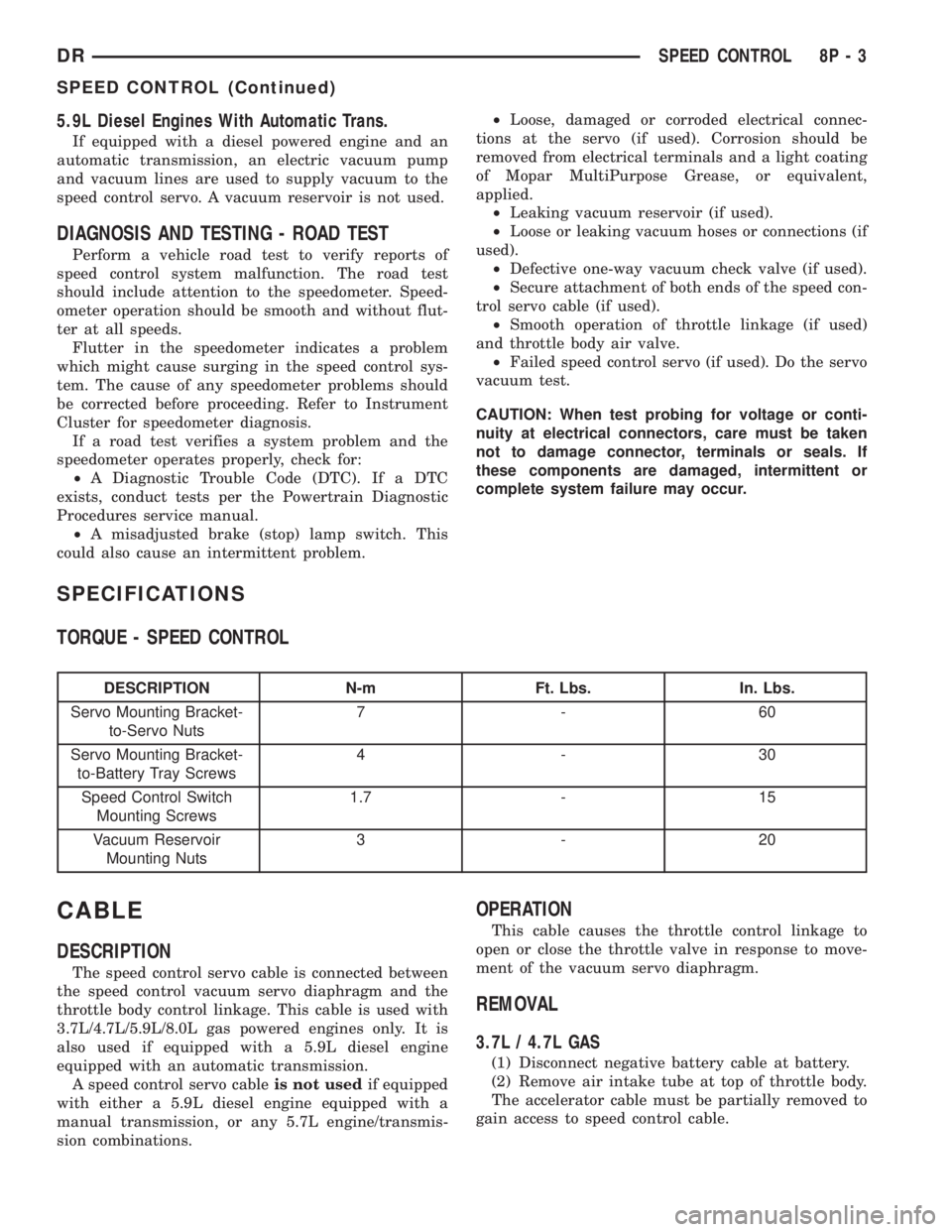
SPECIFICATIONS
TORQUE - SPEED CONTROL
DESCRIPTION N-m Ft. Lbs. In. Lbs.
Servo Mounting Bracket-
to-Servo Nuts7-60
Servo Mounting Bracket-
to-Battery Tray Screws4-30
Speed Control Switch
Mounting Screws1.7 - 15
Vacuum Reservoir
Mounting Nuts3-20
CABLE
DESCRIPTION
The speed control servo cable is connected between
the speed control vacuum servo diaphragm and the
throttle body control linkage. This cable is used with
3.7L/4.7L/5.9L/8.0L gas powered engines only. It is
also used if equipped with a 5.9L diesel engine
equipped with an automatic transmission.
A speed control servo cableis not usedif equipped
with either a 5.9L diesel engine equipped with a
manual transmission, or any 5.7L engine/transmis-
sion combinations.
OPERATION
This cable causes the throttle control linkage to
open or close the throttle valve in response to move-
ment of the vacuum servo diaphragm.
REMOVAL
3.7L / 4.7L GAS
(1) Disconnect negative battery cable at battery.
(2) Remove air intake tube at top of throttle body.
The accelerator cable must be partially removed to
gain access to speed control cable.
DRSPEED CONTROL 8P - 3
SPEED CONTROL (Continued)
Page 1121 of 2895
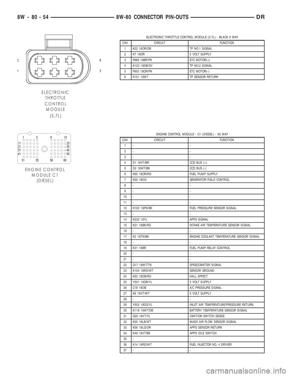
ELECTRONIC THROTTLE CONTROL MODULE (5.7L) - BLACK 6 WAY
CAV CIRCUIT FUNCTION
1 K22 18OR/DB TP NO.1 SIGNAL
2 K7 18OR 5 VOLT SUPPLY
3 F888 18BR/PK ETC MOTOR(+)
4 K122 18DB/GY TP NO.2 SIGNAL
5 F855 18OR/PK ETC MOTOR(-)
6 K101 18WT TP SENSOR RETURN
ENGINE CONTROL MODULE - C1 (DIESEL) - 60 WAY
CAV CIRCUIT FUNCTION
1- -
2- -
3- -
4 D1 18VT/BR CCD BUS (+)
5 D2 18WT/BK CCD BUS (-)
6 K65 18OR/RD FUEL PUMP SUPPLY
7 K20 18DG GENERATOR FIELD CONTROL
8- -
9- -
10 - -
11 - -
12 K102 18PK/BK FUEL PRESSURE SENSOR SIGNAL
13 - -
14 K232 18YL APPS SIGNAL
15 K21 18BK/RD INTAKE AIR TEMPERATURE SENSOR SIGNAL
16 - -
17 K2 18TN/BK ENGINE COOLANT TEMPERATURE SENSOR SIGNAL
18 - -
19 K31 18BR FUEL PUMP RELAY CONTROL
20 - -
21 - -
22 G17 18WT/TN SPEEDOMETER SIGNAL
23 K104 18RD/WT SENSOR GROUND
24 K53 18DB/RD HALL EFFECT
25 Y501 18DB/YL 5 VOLT SUPPLY
26 C18 18DB A/C PRESSURE SIGNAL
27 K6 18VT/WT 5 VOLT SUPPLY
28 - -
29 Y502 18DG/YL INLET AIR TEMPERATURE/PRESSURE RETURN
30 K118 16WT/DB BATTERY TEMPERATURE SENSOR SIGNAL
31 G20 18VT/YL IGNITION SWITCH SENSE
32 K55 18LB/WT MASS AIR FLOW SENSOR SIGNAL
33 K56 18LG/OR APPS SENSOR RETURN
34 K49 18VT/BK APPS IDLE SWITCH
35 - -
36 K14 16RD/WT FUEL INJECTOR NO. 4 DRIVER
37 - -
8W - 80 - 54 8W-80 CONNECTOR PIN-OUTSDR
Page 1174 of 2895
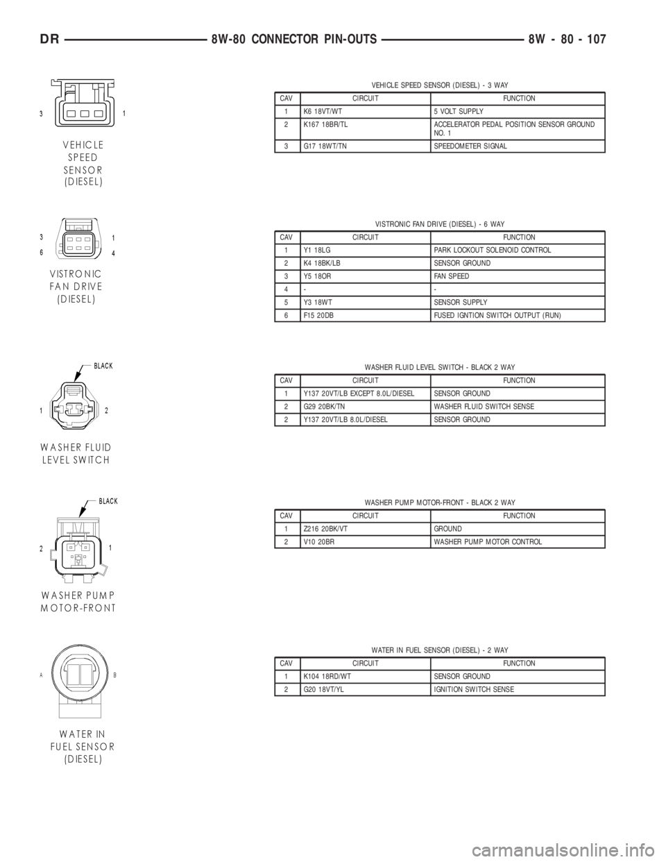
VEHICLE SPEED SENSOR (DIESEL)-3WAY
CAV CIRCUIT FUNCTION
1 K6 18VT/WT 5 VOLT SUPPLY
2 K167 18BR/TL ACCELERATOR PEDAL POSITION SENSOR GROUND
NO. 1
3 G17 18WT/TN SPEEDOMETER SIGNAL
VISTRONIC FAN DRIVE (DIESEL)-6WAY
CAV CIRCUIT FUNCTION
1 Y1 18LG PARK LOCKOUT SOLENOID CONTROL
2 K4 18BK/LB SENSOR GROUND
3 Y5 18OR FAN SPEED
4- -
5 Y3 18WT SENSOR SUPPLY
6 F15 20DB FUSED IGNTION SWITCH OUTPUT (RUN)
WASHER FLUID LEVEL SWITCH - BLACK 2 WAY
CAV CIRCUIT FUNCTION
1 Y137 20VT/LB EXCEPT 8.0L/DIESEL SENSOR GROUND
2 G29 20BK/TN WASHER FLUID SWITCH SENSE
2 Y137 20VT/LB 8.0L/DIESEL SENSOR GROUND
WASHER PUMP MOTOR-FRONT - BLACK 2 WAY
CAV CIRCUIT FUNCTION
1 Z216 20BK/VT GROUND
2 V10 20BR WASHER PUMP MOTOR CONTROL
WATER IN FUEL SENSOR (DIESEL)-2WAY
CAV CIRCUIT FUNCTION
1 K104 18RD/WT SENSOR GROUND
2 G20 18VT/YL IGNITION SWITCH SENSE
DR8W-80 CONNECTOR PIN-OUTS 8W - 80 - 107
Page 1981 of 2895
Test Four - Transmission In Reverse
This test checks pump output, pressure regulation
and the front clutch and rear servo circuits. Use 300
psi Test Gauge C-3293-SP for this test.
(1) Leave vehicle on hoist and leave gauge C-3292
in place at accumulator port.
(2) Move 300 psi Gauge C-3293-SP back to rear
servo port.
(3) Have helper start and run engine at 1600 rpm
for test.
(4) Move transmission shift lever four detents
rearward from full forward position. This is Reverse
range.
(5) Move transmission throttle lever fully forward
then fully rearward and note reading at Gauge
C-3293-SP.
(6) Pressure should be 145 - 175 psi (1000-1207
kPa) with throttle lever forward and increase to 230 -
280 psi (1586-1931 kPa) as lever is gradually moved
rearward.
Test Five - Governor Pressure
This test checks governor operation by measuring
governor pressure response to changes in vehicle
speed. It is usually not necessary to check governor
operation unless shift speeds are incorrect or if the
transmission will not downshift. The test should be
performed on the road or on a hoist that will allow
the rear wheels to rotate freely.
(1) Move 100 psi Test Gauge C-3292 to governor
pressure port.
(2) Move transmission shift lever two detents rear-
ward from full forward position. This is D range.
(3) Have helper start and run engine at curb idle
speed. Then firmly apply service brakes so wheels
will not rotate.
(4) Note governor pressure:
²Governor pressure should be no more than 20.6
kPa (3 psi) at curb idle speed and wheels not rotat-
ing.
²If pressure exceeds 20.6 kPa (3 psi), a fault
exists in governor pressure control system.
(5) Release brakes, slowly increase engine speed,
and observe speedometer and pressure test gauge (do
not exceed 30 mph on speedometer). Governor pres-
sure should increase in proportion to vehicle speed.
Or approximately 6.89 kPa (1 psi) for every 1 mph.
(6) Governor pressure rise should be smooth and
drop back to no more than 20.6 kPa (3 psi), after
engine returns to curb idle and brakes are applied to
prevent wheels from rotating.
(7) Compare results of pressure test with analysis
chart.Test Six - Transmission In Overdrive Fourth Gear
This test checks line pressure at the overdrive
clutch in fourth gear range. Use 300 psi Test Gauge
C-3293-SP for this test. The test should be performed
on the road or on a chassis dyno.
(1) Remove tachometer; it is not needed for this
test.
(2) Move 300 psi Gauge to overdrive clutch pres-
sure test port. Then remove other gauge and reinstall
test port plug.
(3) Lower vehicle.
(4) Turn OD switch on.
(5) Secure test gauge so it can be viewed from
drivers seat.
(6) Start engine and shift into D range.
(7) Increase vehicle speed gradually until 3-4 shift
occurs and note gauge pressure.
(8) Pressure should be 469-496 kPa (68-72 psi)
with closed throttle and increase to 620-827 kPa (90-
120 psi) at 1/2 to 3/4 throttle. Note that pressure can
increase to around 896 kPa (130 psi) at full throttle.
(9) Return to shop or move vehicle off chassis
dyno.
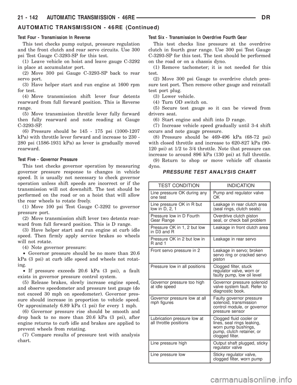
PRESSURE TEST ANALYSIS CHART
TEST CONDITION INDICATION
Line pressure OK during any
one testPump and regulator valve
OK
Line pressure OK in R but
low in D, 2, 1Leakage in rear clutch area
(seal rings, clutch seals)
Pressure low in D Fourth
Gear RangeOverdrive clutch piston
seal, or check ball problem
Pressure OK in 1, 2 but low
in D3 and RLeakage in front clutch area
Pressure OK in 2 but low in
R and 1Leakage in rear servo
Front servo pressure in 2 Leakage in servo; broken
servo ring or cracked servo
piston
Pressure low in all positions Clogged filter, stuck
regulator valve, worn or
faulty pump, low oil level
Governor pressure too high
at idle speedGovernor pressure solenoid
valve system fault. Refer to
diagnostic book.
Governor pressure low at all
mph figuresFaulty governor pressure
solenoid, transmission
control module, or governor
pressure sensor
Lubrication pressure low at
all throttle positionsClogged fluid cooler or
lines, seal rings leaking,
worn pump bushings,
pump, clutch retainer, or
clogged filter.
Line pressure high Output shaft plugged, sticky
regulator valve
Line pressure low Sticky regulator valve,
clogged filter, worn pump
21 - 142 AUTOMATIC TRANSMISSION - 46REDR
AUTOMATIC TRANSMISSION - 46RE (Continued)
Page 2036 of 2895
Normal calibration will be performed when sump
temperature is above 50 degrees F, or in the absence
of sump temperature data, after the first 10 minutes
of vehicle operation. Calibration of the pressure
transducer offset occurs each time the output shaft
speed falls below 200 RPM. Calibration shall be
repeated each 3 seconds the output shaft speed is
below 200 RPM. A 0.5 second pulse of 95% duty cycle
is applied to the governor pressure solenoid valve
and the transducer output is read during this pulse.
Averaging of the transducer signal is necessary to
reject electrical noise.
Under cold conditions (below 50 degrees F sump),
the governor pressure solenoid valve response may
be too slow to guarantee 0 psi during the 0.5 second
calibration pulse. Calibration pulses are continued
during this period, however the transducer output
valves are discarded. Transducer offset must be read
at key-on, under conditions which promote a stable
reading. This value is retained and becomes the off-
set during the9cold9period of operation.
GOVERNOR PRESSURE SOLENOID VALVE
The inlet side of the solenoid valve is exposed to
normal transmission line pressure. The outlet side of
the valve leads to the valve body governor circuit.
The solenoid valve regulates line pressure to pro-
duce governor pressure. The average current sup-
plied to the solenoid controls governor pressure. One
amp current produces zero kPa/psi governor pres-
sure. Zero amps sets the maximum governor pres-
sure.
The powertrain control module (PCM) turns on the
trans control relay which supplies electrical power to
the solenoid valve. Operating voltage is 12 volts
(DC). The PCM controls the ground side of the sole-
noid using the governor pressure solenoid control cir-
cuit.
GOVERNOR PRESSURE SENSOR
The sensor output signal provides the necessary
feedback to the PCM. This feedback is needed to ade-
quately control governor pressure.
GOVERNOR BODY AND TRANSFER PLATE
The transfer plate channels line pressure to the
solenoid valve through the governor body. It also
channels governor pressure from the solenoid valve
to the governor circuit. It is the solenoid valve that
develops the necessary governor pressure.
GOVERNOR PRESSURE CURVES
LOW TRANSMISSION FLUID TEMPERATURE
When the transmission fluid is cold the conven-
tional governor can delay shifts, resulting in higherthan normal shift speeds and harsh shifts. The elec-
tronically controlled low temperature governor pres-
sure curve is higher than normal to make the
transmission shift at normal speeds and sooner. The
PCM uses a temperature sensor in the transmission
oil sump to determine when low temperature gover-
nor pressure is needed.
NORMAL OPERATION
Normal operation is refined through the increased
computing power of the PCM and through access to
data on engine operating conditions provided by the
PCM that were not available with the previous
stand-alone electronic module. This facilitated the
development of a load adaptive shift strategy - the
ability to alter the shift schedule in response to vehi-
cle load condition. One manifestation of this capabil-
ity is grade9hunting9prevention - the ability of the
transmission logic to delay an upshift on a grade if
the engine does not have sufficient power to main-
tain speed in the higher gear. The 3-2 downshift and
the potential for hunting between gears occurs with a
heavily loaded vehicle or on steep grades. When
hunting occurs, it is very objectionable because shifts
are frequent and accompanied by large changes in
noise and acceleration.
WIDE OPEN THROTTLE OPERATION
In wide-open throttle (WOT) mode, adaptive mem-
ory in the PCM assures that up-shifts occur at the
preprogrammed optimum speed. WOT operation is
determined from the throttle position sensor, which
is also a part of the emission control system. The ini-
tial setting for the WOT upshift is below the opti-
mum engine speed. As WOT shifts are repeated, the
PCM learns the time required to complete the shifts
by comparing the engine speed when the shifts occur
to the optimum speed. After each shift, the PCM
adjusts the shift point until the optimum speed is
reached. The PCM also considers vehicle loading,
grade and engine performance changes due to high
altitude in determining when to make WOT shifts. It
does this by measuring vehicle and engine accelera-
tion and then factoring in the shift time.
TRANSFER CASE LOW RANGE OPERATION
On four-wheel drive vehicles operating in low
range, the engine can accelerate to its peak more
rapidly than in Normal range, resulting in delayed
shifts and undesirable engine9flare.9The low range
governor pressure curve is also higher than normal
to initiate upshifts sooner. The PCM compares elec-
tronic vehicle speed signal used by the speedometer
to the transmission output shaft speed signal to
determine when the transfer case is in low range.
DRAUTOMATIC TRANSMISSION - 46RE 21 - 197
ELECTRONIC GOVERNOR (Continued)
Page 2162 of 2895
(3) Have helper start and run engine at 1600 rpm
for test.
(4) Move transmission shift lever four detents
rearward from full forward position. This is Reverse
range.
(5) Move transmission throttle lever fully forward
then fully rearward and note reading at Gauge
C-3293-SP.
(6) Pressure should be 145 - 175 psi (1000-1207
kPa) with throttle lever forward and increase to 230 -
280 psi (1586-1931 kPa) as lever is gradually moved
rearward.
Test Five - Governor Pressure
This test checks governor operation by measuring
governor pressure response to changes in vehicle
speed. It is usually not necessary to check governor
operation unless shift speeds are incorrect or if the
transmission will not downshift. The test should be
performed on the road or on a hoist that will allow
the rear wheels to rotate freely.
(1) Move 100 psi Test Gauge C-3292 to governor
pressure port.
(2) Move transmission shift lever two detents rear-
ward from full forward position. This is D range.
(3) Have helper start and run engine at curb idle
speed. Then firmly apply service brakes so wheels
will not rotate.
(4) Note governor pressure:
²Governor pressure should be no more than 20.6
kPa (3 psi) at curb idle speed and wheels not rotat-
ing.
²If pressure exceeds 20.6 kPa (3 psi), a fault
exists in governor pressure control system.
(5) Release brakes, slowly increase engine speed,
and observe speedometer and pressure test gauge (do
not exceed 30 mph on speedometer). Governor pres-
sure should increase in proportion to vehicle speed.
Or approximately 6.89 kPa (1 psi) for every 1 mph.
(6) Governor pressure rise should be smooth and
drop back to no more than 20.6 kPa (3 psi), after
engine returns to curb idle and brakes are applied to
prevent wheels from rotating.
(7) Compare results of pressure test with analysis
chart.
Test Six - Transmission In Overdrive Fourth Gear
This test checks line pressure at the overdrive
clutch in fourth gear range. Use 300 psi Test Gauge
C-3293-SP for this test. The test should be performed
on the road or on a chassis dyno.
(1) Remove tachometer; it is not needed for this
test.
(2) Move 300 psi Gauge to overdrive clutch pres-
sure test port. Then remove other gauge and reinstall
test port plug.(3) Lower vehicle.
(4) Turn OD switch on.
(5) Secure test gauge so it can be viewed from
drivers seat.
(6) Start engine and shift into D range.
(7) Increase vehicle speed gradually until 3-4 shift
occurs and note gauge pressure.
(8) Pressure should be 524-565 kPa (76-82 psi)
with closed throttle and increase to 690-896 kPa
(100-130 psi) at 1/2 to 3/4 throttle. Note that pres-
sure can increase to around 965 kPa (140 psi) at full
throttle.
(9) Return to shop or move vehicle off chassis
dyno.
PRESSURE TEST ANALYSIS CHART
TEST CONDITION INDICATION
Line pressure OK during
any one testPump and regulator valve
OK
Line pressure OK in R but
low in D, 2, 1Leakage in rear clutch
area (seal rings, clutch
seals)
Pressure low in D Fourth
Gear RangeOverdrive clutch piston
seal, or check ball
problem
Pressure OK in 1, 2 but
low in D3 and RLeakage in front clutch
area
Pressure OK in 2 but low
in R and 1Leakage in rear servo
Front servo pressure in 2 Leakage in servo; broken
servo ring or cracked
servo piston
Pressure low in all
positionsClogged filter, stuck
regulator valve, worn or
faulty pump, low oil level
Governor pressure too
high at idle speedGovernor pressure
solenoid valve system
fault. Refer to diagnostic
book.
Governor pressure low at
all mph figuresFaulty governor pressure
solenoid, transmission
control module, or
governor pressure sensor
Lubrication pressure low
at all throttle positionsClogged fluid cooler or
lines, seal rings leaking,
worn pump bushings,
pump, clutch retainer, or
clogged filter.
Line pressure high Output shaft plugged,
sticky regulator valve
Line pressure low Sticky regulator valve,
clogged filter, worn pump
DRAUTOMATIC TRANSMISSION - 48RE 21 - 323
AUTOMATIC TRANSMISSION - 48RE (Continued)
Page 2217 of 2895
GOVERNOR PRESSURE SENSOR
The sensor output signal provides the necessary
feedback to the PCM. This feedback is needed to ade-
quately control governor pressure.
GOVERNOR BODY AND TRANSFER PLATE
The transfer plate channels line pressure to the
solenoid valve through the governor body. It also
channels governor pressure from the solenoid valve
to the governor circuit. It is the solenoid valve that
develops the necessary governor pressure.
GOVERNOR PRESSURE CURVES
LOW TRANSMISSION FLUID TEMPERATURE
When the transmission fluid is cold the conven-
tional governor can delay shifts, resulting in higher
than normal shift speeds and harsh shifts. The elec-
tronically controlled low temperature governor pres-
sure curve is higher than normal to make the
transmission shift at normal speeds and sooner. The
PCM uses a temperature sensor in the transmission
oil sump to determine when low temperature gover-
nor pressure is needed.
NORMAL OPERATION
Normal operation is refined through the increased
computing power of the PCM and through access to
data on engine operating conditions provided by the
PCM that were not available with the previous
stand-alone electronic module. This facilitated the
development of a load adaptive shift strategy - the
ability to alter the shift schedule in response to vehi-
cle load condition. One manifestation of this capabil-
ity is grade9hunting9prevention - the ability of the
transmission logic to delay an upshift on a grade if
the engine does not have sufficient power to main-
tain speed in the higher gear. The 3-2 downshift and
the potential for hunting between gears occurs with a
heavily loaded vehicle or on steep grades. When
hunting occurs, it is very objectionable because shifts
are frequent and accompanied by large changes in
noise and acceleration.
WIDE OPEN THROTTLE OPERATION
In wide-open throttle (WOT) mode, adaptive mem-
ory in the PCM assures that up-shifts occur at the
preprogrammed optimum speed. WOT operation is
determined from the throttle position sensor, which
is also a part of the emission control system. The ini-tial setting for the WOT upshift is below the opti-
mum engine speed. As WOT shifts are repeated, the
PCM learns the time required to complete the shifts
by comparing the engine speed when the shifts occur
to the optimum speed. After each shift, the PCM
adjusts the shift point until the optimum speed is
reached. The PCM also considers vehicle loading,
grade and engine performance changes due to high
altitude in determining when to make WOT shifts. It
does this by measuring vehicle and engine accelera-
tion and then factoring in the shift time.
TRANSFER CASE LOW RANGE OPERATION
On four-wheel drive vehicles operating in low
range, the engine can accelerate to its peak more
rapidly than in Normal range, resulting in delayed
shifts and undesirable engine9flare.9The low range
governor pressure curve is also higher than normal
to initiate upshifts sooner. The PCM compares elec-
tronic vehicle speed signal used by the speedometer
to the transmission output shaft speed signal to
determine when the transfer case is in low range.
REMOVAL
(1) Hoist and support vehicle on safety stands.
(2) Remove transmission fluid pan and filter.
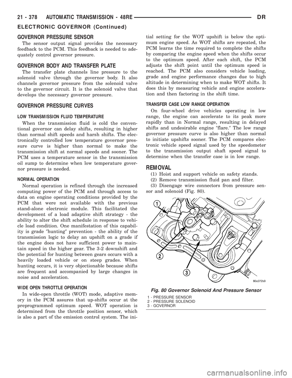
(3) Disengage wire connectors from pressure sen-
sor and solenoid (Fig. 80).
Fig. 80 Governor Solenoid And Pressure Sensor
1 - PRESSURE SENSOR
2 - PRESSURE SOLENOID
3 - GOVERNOR
21 - 378 AUTOMATIC TRANSMISSION - 48REDR
ELECTRONIC GOVERNOR (Continued)
Page 2887 of 2895
SIDE - REMOVAL, LEFT................9-121
SIDE - REMOVAL, RIGHT..............9-121
SIDE BEZEL - INSTALLATION,
INSTRUMENT PANEL DRIVER...........23-59
SIDE BEZEL - REMOVAL, INSTRUMENT
PANEL DRIVER......................23-58
SIDE CURTAIN AIRBAG - DESCRIPTION . . . 8O-51
SIDE CURTAIN AIRBAG - INSTALLATION . . 8O-53
SIDE CURTAIN AIRBAG - OPERATION....8O-51
SIDE CURTAIN AIRBAG - REMOVAL......8O-52
SIDE IMPACT AIRBAG CONTROL
MODULE - DESCRIPTION..............8O-53
SIDE IMPACT AIRBAG CONTROL
MODULE - OPERATION................8O-54
SIDE MOLDINGS - INSTALLATION, BODY . . 23-36
SIDE MOLDINGS - REMOVAL, BODY.....23-36
SIDE VIEW MIRROR - INSTALLATION.....23-41
SIDE VIEW MIRROR - REMOVAL........23-41
SIDE VIEW MIRROR FLAG -
INSTALLATION.......................23-27
SIDE VIEW MIRROR FLAG - REMOVAL . . . 23-27
SIDE VIEW MIRROR GLASS -
INSTALLATION.......................23-44
SIDE VIEW MIRROR GLASS - REMOVAL . . 23-42
SIDEVIEW MIRROR - REMOVAL.........8N-13
SIGNAL INDICATOR - DESCRIPTION,
TURN..............................8J-39
SIGNAL INDICATOR - OPERATION, TURN . . 8J-39
SIGNAL LAMP - INSTALLATION,
PARK/TURN.........................8L-21
SIGNAL LAMP - REMOVAL, PARK/TURN . . 8L-21
SIGNAL SYSTEM - DESCRIPTION, TURN . . 8L-17
SIGNAL SYSTEM - OPERATION, TURN....8L-18
SILL TRIM COVER - INSTALLATION,
REAR DOOR........................23-72
SILL TRIM COVER - REMOVAL, REAR
DOOR.............................23-72
SINGLE CARDAN UNIVERSAL JOINTS -
ASSEMBLY...........................3-9
SINGLE CARDAN UNIVERSAL JOINTS -
DISASSEMBLY.........................3-9
SIZE, SPARE WHEEL WITH MATCHING
TIRE - DESCRIPTION, FULL............22-15
SKID PLATE - INSTALLATION, FRONT.....13-24
SKID PLATE - INSTALLATION, TRANSFER
CASE..............................13-26
SKID PLATE - REMOVAL, FRONT........13-24
SKID PLATE - REMOVAL, TRANSFER
CASE..............................13-26
SLEEVE - INSTALLATION, HEADREST.....23-82
SLEEVE - REMOVAL, HEADREST........23-82
SMOKE DIAGNOSIS CHARTS -
DIAGNOSIS AND TESTING.............9-285
SOLENOID - DESCRIPTION......21-253,21-431
SOLENOID - DESCRIPTION, EVAP/PURGE . 25-12
SOLENOID - INSTALLATION, EVAP/
PURGE.............................25-13
SOLENOID - OPERATION........21-254,21-431
SOLENOID - OPERATION, EVAP/PURGE . . . 25-12
SOLENOID - REMOVAL, EVAP/PURGE.....25-13
SOLENOID SWITCH VALVE -
DESCRIPTION......................21-574
SOLENOID SWITCH VALVE - OPERATION . 21-574
SOLENOIDS - DESCRIPTION...........21-574
SOLENOIDS - OPERATION.............21-575
SOLENOID/TRS ASSEMBLY -
DESCRIPTION, TRANSMISSION........21-582
SOLENOID/TRS ASSEMBLY -
INSTALLATION, TRANSMISSION........21-583
SOLENOID/TRS ASSEMBLY -
OPERATION, TRANSMISSION..........21-582
SOLENOID/TRS ASSEMBLY - REMOVAL,
TRANSMISSION.....................21-583
SOLID LIFTERS/TAPPETS - CLEANING....9-328
SOLID LIFTERS/TAPPETS - INSPECTION . . 9-328
SOLID LIFTERS/TAPPETS -
INSTALLATION.......................9-328
SOLID LIFTERS/TAPPETS - REMOVAL....9-327
SPARE / TEMPORARY TIRE -
DESCRIPTION.......................22-15
SPARE TIRE / TEMPORARY -
DESCRIPTION........................22-5
SPARE WHEEL WITH MATCHING TIRE -
DESCRIPTION, FULL SIZE
..............22-15
SPARK PLUG - DESCRIPTION
...........8I-27
SPARK PLUG - REMOVAL
..............8I-30
SPARK PLUG CABLE - DESCRIPTION
.....8I-33
SPARK PLUG CABLE - INSTALLATION
.....8I-35SPARK PLUG CABLE - OPERATION.......8I-33
SPARK PLUG CABLE - REMOVAL........8I-34
SPARK PLUG CABLE ORDER, 8.0L V-10
ENGINE..............................8I-5
SPARK PLUG CABLE RESISTANCE,
SPECIFICATIONS......................8I-5
SPARK PLUG CABLES - DIAGNOSIS AND
TESTING............................8I-33
SPARK PLUG CONDITIONS - DIAGNOSIS
AND TESTING........................8I-27
SPARK PLUGS, SPECIFICATIONS..........8I-5
SPEAKER - DESCRIPTION..............8A-12
SPEAKER - DIAGNOSIS AND TESTING....8A-13
SPEAKER - INSTALLATION.............8A-15
SPEAKER - OPERATION...............8A-12
SPEAKER - REMOVAL.................8A-13
SPECIFICATIONS......................7-20
SPEED CONTROL - DESCRIPTION........8P-1
SPEED CONTROL - OPERATION..........8P-2
SPEED CONTROL - TORQUE.............8P-3
SPEED SENSOR - DESCRIPTION . . 21-254,21-431
SPEED SENSOR - DESCRIPTION, FRONT
WHEEL.............................5-41
SPEED SENSOR - DESCRIPTION, INPUT . 21-558
SPEED SENSOR - DESCRIPTION,
OUTPUT...........................21-567
SPEED SENSOR - DIAGNOSIS AND
TESTING, REAR WHEEL................5-43
SPEED SENSOR - INSTALLATION, FRONT
WHEEL.............................5-42
SPEED SENSOR - INSTALLATION, INPUT . 21-559
SPEED SENSOR - INSTALLATION,
OUTPUT...........................21-567
SPEED SENSOR - INSTALLATION, REAR
WHEEL.............................5-43
SPEED SENSOR - OPERATION . . . 21-254,21-431
SPEED SENSOR - OPERATION, FRONT
WHEEL.............................5-41
SPEED SENSOR - OPERATION, INPUT . . . 21-558
SPEED SENSOR - OPERATION, OUTPUT . . 21-567
SPEED SENSOR - REMOVAL, FRONT
WHEEL.............................5-41
SPEED SENSOR - REMOVAL, INPUT.....21-559
SPEED SENSOR - REMOVAL, OUTPUT . . . 21-567
SPEED SENSOR - REMOVAL, REAR
WHEEL.............................5-42
SPEEDOMETER - DESCRIPTION.........8J-36
SPEEDOMETER - OPERATION...........8J-36
SPEEDS - DESCRIPTION, TIRE
PRESSURE FOR HIGH..................22-6
SPLASH SHIELD - INSTALLATION,
FRONT WHEELHOUSE.................23-41
SPLASH SHIELD - INSTALLATION, REAR
WHEELHOUSE.......................23-41
SPLASH SHIELD - REMOVAL, FRONT
WHEELHOUSE.......................23-40
SPLASH SHIELD - REMOVAL, REAR
WHEELHOUSE.......................23-41
SPLICE INFORMATION - DESCRIPTION,
CONNECTOR, GROUND..............8W-01-7
SPLICING - STANDARD PROCEDURE,
WIRE...........................8W-01-15
SPRING - DESCRIPTION................2-41
SPRING - INSTALLATION.......2-22,2-36,2-41
SPRING - OPERATION..................2-41
SPRING - REMOVAL...........2-21,2-36,2-41
SPRING AND SHOCK - DIAGNOSIS AND
TESTING............................2-38
SPRING BUMPERS (3500) -
INSTALLATION, AUXILIARY..............2-40
SPRING BUMPERS (3500) - REMOVAL,
AUXILIARY..........................2-40
SPRING TIP INSERTS - INSTALLATION....2-42
SPRING TIP INSERTS - REMOVAL........2-41
SPRINGS - DESCRIPTION, VALVE . . . 9-125,9-31,
9-36
SPRINGS - INSTALLATION, VALVE . . 9-126,9-199,
9-31,9-37
SPRINGS - INSTALLATION, VALVES AND
VALVE
.............................9-379
SPRINGS - REMOVAL, VALVE
. 9-125,9-199,9-31,
9-37
SPRINGS - REMOVAL, VALVES AND
VALVE
.............................9-377
SPRINGS - STANDARD PROCEDURE,
VALVES, GUIDES
................9-246,9-305
SPRINGS AND SEALS - REMOVAL,
VALVE
.............................9-308SPROCKETS - INSPECTION, TIMING
BELT/CHAIN.....................9-171,9-83
SPROCKETS - INSTALLATION, TIMING
BELT/CHAIN...........9-172,9-279,9-406,9-84
SPROCKETS - INSTALLATION,
TIMING/CHAIN.......................9-222
SPROCKETS - REMOVAL, TIMING
BELT/CHAIN...........9-169,9-279,9-405,9-81
SPROCKETS - REMOVAL, TIMING/CHAIN . . 9-221
SQUEAK & RATTLE - STANDARD
PROCEDURE, BUZZ...................23-11
STABILIZER BAR - DESCRIPTION.........2-24
STABILIZER BAR - INSTALLATION....2-24,2-37
STABILIZER BAR - OPERATION...........2-24
STABILIZER BAR - REMOVAL........2-24,2-37
STAKING - STANDARD PROCEDURE,
HEAT ...............................23-3
STANDARD CAB - INSTALLATION........8O-31
STANDARD CAB - REMOVAL...........8O-28
STARTER MOTOR - DIAGNOSIS AND
TESTING...........................8F-34
STARTER MOTOR - INSTALLATION.......8F-37
STARTER MOTOR - REMOVAL..........8F-34
STARTER MOTOR RELAY - DESCRIPTION . 8F-38
STARTER MOTOR RELAY -
INSTALLATION.......................8F-39
STARTER MOTOR RELAY - OPERATION . . . 8F-38
STARTER MOTOR RELAY - REMOVAL.....8F-39
STARTER RELAY - DIAGNOSIS AND
TESTING.............................8F-38
STARTING - DESCRIPTION.............8F-28
STARTING - OPERATION...............8F-28
STARTING - STANDARD PROCEDURE,
JUMP...............................0-13
STARTING SYSTEM - DIAGNOSIS AND
TESTING...........................8F-29
STARTING SYSTEM - SPECIFICATIONS,
TORQUE............................8F-34
STARTING SYSTEM, SPECIFICATIONS.....8F-33
STATE DISPLAY TEST MODE -
DESCRIPTION........................25-1
STEERING - DESCRIPTION..............19-1
STEERING - OPERATION................19-1
STEERING COLUMN - DIAGNOSIS AND
TESTING............................19-7
STEERING COLUMN OPENING COVER -
INSTALLATION.......................23-61
STEERING COLUMN OPENING COVER -
REMOVAL..........................23-61
STEERING COLUMN OPENING SUPPORT
BRACKET - INSTALLATION.............23-62
STEERING COLUMN OPENING SUPPORT
BRACKET - REMOVAL.................23-61
STEERING COUPLING - INSTALLATION,
UPPER.............................19-14
STEERING COUPLING - REMOVAL,
UPPER.............................19-13
STEERING FLOW AND PRESSURE -
DIAGNOSIS AND TESTING, POWER.......19-4
STEERING FLUID - DESCRIPTION,
POWER..............................0-3
STEERING FLUID LEVEL CHECKING -
STANDARD PROCEDURE, POWER.......19-42
STEERING GEAR INPUT SHAFT SEAL -
INSTALLATION.......................19-28
STEERING GEAR INPUT SHAFT SEAL -
REMOVAL..........................19-25
STEERING GEAR, SPECIAL TOOLS -
POWER............................19-22
STEERING GEAR, SPECIFICATIONS -
POWER............................19-21
STEERING LINKAGE, SPECIAL TOOLS....19-35
STEERING PRESSURE SWITCH -
DESCRIPTION, POWER................19-45
STEERING PRESSURE SWITCH -
OPERATION, POWER..................19-45
STEERING PUMP - INITIAL OPERATION -
STANDARD PROCEDURE, POWER.......19-39
STEERING, SPECIAL TOOLS.............19-5
STEERING SYSTEM - DIAGNOSIS AND
TESTING, POWER.....................19-2
STEERING SYSTEM - STANDARD
PROCEDURE, FLUSHING POWER
........19-39
STEERING WHEEL - INSTALLATION
......19-15
STEERING WHEEL - REMOVAL
..........19-15
STEM SEAL - INSTALLATION, VALVE
.....9-378
STEM SEALS - DESCRIPTION, VALVE
....9-126,
9-198
32 INDEXDR
Description Group-Page Description Group-Page Description Group-Page