2003 DODGE RAM electrical
[x] Cancel search: electricalPage 638 of 2895
take out and connector for the airbag inflator located
on the inboard side of the housing.
(9) Disconnect the instrument panel wire harness
connector for the passenger airbag from the connec-
tor receptacle on the airbag inflator.
(10) Remove the passenger airbag and airbag door
from the instrument panel as a unit.
INSTALLATION
The following procedure is for replacement of a
faulty or damaged passenger airbag. If the airbag is
faulty or damaged, but not deployed, review the rec-
ommended procedures for handling non-deployed
supplemental restraints. (Refer to 8 - ELECTRICAL/
RESTRAINTS - STANDARD PROCEDURE - HAN-
DLING NON-DEPLOYED SUPPLEMENTAL
RESTRAINTS). If the passenger airbag has been
deployed, review the recommended procedures for
service after a supplemental restraint deployment
before removing the airbag from the vehicle. (Refer to
8 - ELECTRICAL/RESTRAINTS - STANDARD PRO-
CEDURE - SERVICE AFTER A SUPPLEMENTAL
RESTRAINT DEPLOYMENT).
WARNING: ON VEHICLES EQUIPPED WITH AIR-
BAGS, DISABLE THE SUPPLEMENTAL RESTRAINT
SYSTEM BEFORE ATTEMPTING ANY STEERING
WHEEL, STEERING COLUMN, DRIVER AIRBAG,
PASSENGER AIRBAG, SEAT BELT TENSIONER,
SIDE CURTAIN AIRBAG, OR INSTRUMENT PANEL
COMPONENT DIAGNOSIS OR SERVICE. DISCON-
NECT AND ISOLATE THE BATTERY NEGATIVE
(GROUND) CABLE, THEN WAIT TWO MINUTES FOR
THE SYSTEM CAPACITOR TO DISCHARGE BEFORE
PERFORMING FURTHER DIAGNOSIS OR SERVICE.
THIS IS THE ONLY SURE WAY TO DISABLE THE
SUPPLEMENTAL RESTRAINT SYSTEM. FAILURE TO
TAKE THE PROPER PRECAUTIONS COULD
RESULT IN ACCIDENTAL AIRBAG DEPLOYMENT
AND POSSIBLE PERSONAL INJURY.
WARNING: WHEN REMOVING A DEPLOYED AIR-
BAG, RUBBER GLOVES, EYE PROTECTION, AND A
LONG-SLEEVED SHIRT SHOULD BE WORN. THERE
MAY BE DEPOSITS ON THE AIRBAG UNIT AND
OTHER INTERIOR SURFACES. IN LARGE DOSES,
THESE DEPOSITS MAY CAUSE IRRITATION TO THE
SKIN AND EYES.
WARNING: USE EXTREME CARE TO PREVENT ANY
FOREIGN MATERIAL FROM ENTERING THE PAS-
SENGER AIRBAG, OR BECOMING ENTRAPPED
BETWEEN THE PASSENGER AIRBAG CUSHION
AND THE PASSENGER AIRBAG DOOR. FAILURE TOOBSERVE THIS WARNING COULD RESULT IN
OCCUPANT INJURIES UPON AIRBAG DEPLOY-
MENT.
WARNING: THE PASSENGER AIRBAG DOOR MUST
NEVER BE PAINTED. REPLACEMENT PASSENGER
AIRBAG UNITS ARE SERVICED WITH DOORS IN
THE ORIGINAL COLORS. PAINT MAY CHANGE THE
WAY IN WHICH THE MATERIAL OF THE AIRBAG
DOOR RESPONDS TO AN AIRBAG DEPLOYMENT.
FAILURE TO OBSERVE THIS WARNING COULD
RESULT IN OCCUPANT INJURIES UPON AIRBAG
DEPLOYMENT.
(1) Carefully position the passenger airbag and
airbag door to the instrument panel as a unit.
(2) Reconnect the instrument panel wire harness
connector for the passenger airbag to the connector
receptacle on the airbag inflator. Be certain that the
connector latches are fully engaged.
(3) Position the passenger airbag housing and door
unit into the instrument panel.
(4) Using hand pressure, press firmly and evenly
over each of the seven snap features on the upper
and outboard edges of the passenger airbag door
until they snap into their receptacles in the instru-
ment panel base trim.
(5) Reach through and above the glove box opening
to install and tighten the two screws that secure the
passenger airbag front brackets to the instrument
panel structural support (Fig. 33). Tighten the screws
to 6 N´m (55 in. lbs.).
(6) Reach through and above the glove box opening
to install and tighten the two screws that secure the
passenger airbag rear brackets to the upper glove
box opening reinforcement. Tighten the screws to 6
N´m (55 in. lbs.).
(7) Install and tighten the six screws that secure
the inboard and lower flanges of the passenger air-
bag door to the instrument panel (Fig. 32). Tighten
the screws to 2 N´m (20 in. lbs.).
(8) Install and tighten the two screws that secure
the mounting tabs of the two panel outlet housings to
the upper glove box opening reinforcement. Tighten
the screws to 2 N´m (20 in. lbs.).
(9) Reinstall the lower surround onto the instru-
ment panel. (Refer to 23 - BODY/INSTRUMENT
PANEL/LOWER SURROUND - INSTALLATION).
(10) Do not reconnect the battery negative cable at
this time. The supplemental restraint system verifi-
cation test procedure should be performed following
service of any supplemental restraint system compo-
nent. (Refer to 8 - ELECTRICAL/RESTRAINTS -
STANDARD PROCEDURE - VERIFICATION TEST).
DRRESTRAINTS 8O - 37
PASSENGER AIRBAG (Continued)
Page 639 of 2895

PASSENGER AIRBAG ON/OFF
SWITCH
DESCRIPTION
The passenger airbag on/off switch is standard
equipment on all standard cab versions of this model
when they are equipped with the dual front airbag
system (Fig. 35). This switch is a two-position, resis-
tor multiplexed switch with a single integral red
Light-Emitting Diode (LED), and a non-coded key
cylinder-type actuator. The switch is located in the
lower right corner of instrument panel center bezel,
near the center of instrument panel to make the Off
indicator visible to all front seat occupants. When the
switch is in its installed position, the only compo-
nents visible through the dedicated opening of the
cluster bezel are the switch face plate and nomencla-
ture, and the key cylinder actuator. The9Off9position
of the switch is illuminated when this switch position
is selected, while the ªOnº position of the switch is
designated by text imprinted upon the face plate of
the switch, but is not illuminated. The remainder of
the switch is concealed behind the switch face plate
and the instrument panel center bezel.
The passenger airbag on/off switch housing is con-
structed of molded plastic and has three integral
mounting tabs. These mounting tabs are used to
secure the switch to the back of the molded plastic
switch face plate with three small screws. The
molded plastic face plate also has three integral
mounting tabs that are used to secure the switch and
face plate unit to the instrument panel center bezel
with three additional screws. A molded plastic con-
nector receptacle on the back of the switch housingconnects the switch to the vehicle electrical system
through a dedicated take out and connector of the
instrument panel wire harness. The molded plastic
harness connector insulator is keyed and latched to
ensure proper and secure switch electrical connec-
tions. The passenger airbag on/off switch cannot be
adjusted or repaired and, if faulty or damaged, the
switch must be replaced.
OPERATION
The passenger airbag on/off switch allows the cus-
tomer to turn the passenger airbag function On or
Off to accommodate certain uses of the right front
seating position where airbag protection may not be
desired. See the owner's manual in the vehicle glove
box for specific recommendations on when to enable
or disable the passenger airbag. The Off indicator of
the switch will be illuminated whenever the switch is
turned to the Off position and the ignition switch is
in the On position.
The ignition key is the only key or object that
should ever be inserted into the key cylinder actuator
of the switch. The on/off switch requires only a par-
tial key insertion to fully depress a spring-loaded
locking plunger. The spring-loaded locking plunger
prevents the user from leaving the key in the switch.
The key will be automatically ejected when force is
not applied. To actuate the passenger airbag on/off
switch, insert the ignition key into the switch key
actuator far enough to fully depress the plunger, then
rotate the actuator to the desired switch position.
When the switch key actuator is rotated to its clock-
wise stop (the key actuator slot will be aligned with
the Off indicator), the Off indicator is illuminated
and the passenger airbag is disabled. When the
switch is rotated to its counterclockwise stop (the key
actuator slot will be in a vertical position), the Off
indicator will be extinguished and the passenger air-
bag is enabled.
The passenger airbag on/off switch connects one of
two internal resistors in series between the passen-
ger airbag mux switch sense and passenger airbag
mux switch return circuits of the Airbag Control
Module (ACM). The ACM continually monitors the
resistance in these circuits to determine the switch
position that has been selected. When the switch is
in the Off position, the ACM provides a ground input
to the switch through the passenger airbag indicator
driver circuit, which energizes the Light-Emitting
Diode (LED) that illuminates the Off indicator of the
switch.
The ACM will also illuminate the Off indicator of
the switch for about seven seconds each time the
ignition switch is turned to the On position as a bulb
test. The ACM will store a Diagnostic Trouble Code
(DTC) for any fault it detects in the passenger airbag
Fig. 35 Passenger Airbag On/Off Switch
1 - SWITCH
2 - FACE PLATE
3 - OFF INDICATOR
4 - KEY CYLINDER ACTUATOR
8O - 38 RESTRAINTSDR
Page 640 of 2895
on/off switch or Off indicator circuits, and will illumi-
nate the airbag indicator in the instrument cluster if
a fault is detected. For proper diagnosis of the pas-
senger airbag on/off switch or the ACM, a DRBIIIt
scan tool is required. Refer to the appropriate diag-
nostic information.
REMOVAL
WARNING: ON VEHICLES EQUIPPED WITH AIR-
BAGS, DISABLE THE SUPPLEMENTAL RESTRAINT
SYSTEM BEFORE ATTEMPTING ANY STEERING
WHEEL, STEERING COLUMN, DRIVER AIRBAG,
PASSENGER AIRBAG, SEAT BELT TENSIONER,
SIDE CURTAIN AIRBAG, OR INSTRUMENT PANEL
COMPONENT DIAGNOSIS OR SERVICE. DISCON-
NECT AND ISOLATE THE BATTERY NEGATIVE
(GROUND) CABLE, THEN WAIT TWO MINUTES FOR
THE SYSTEM CAPACITOR TO DISCHARGE BEFORE
PERFORMING FURTHER DIAGNOSIS OR SERVICE.
THIS IS THE ONLY SURE WAY TO DISABLE THE
SUPPLEMENTAL RESTRAINT SYSTEM. FAILURE TO
TAKE THE PROPER PRECAUTIONS COULD
RESULT IN ACCIDENTAL AIRBAG DEPLOYMENT
AND POSSIBLE PERSONAL INJURY.
(1) Disconnect and isolate the battery negative
cable. Wait two minutes for the system capacitor to
discharge before further service.
(2) Remove the center bezel from the instrument
panel. (Refer to 23 - BODY/INSTRUMENT PANEL/
INSTRUMENT PANEL CENTER BEZEL - REMOV-
AL).
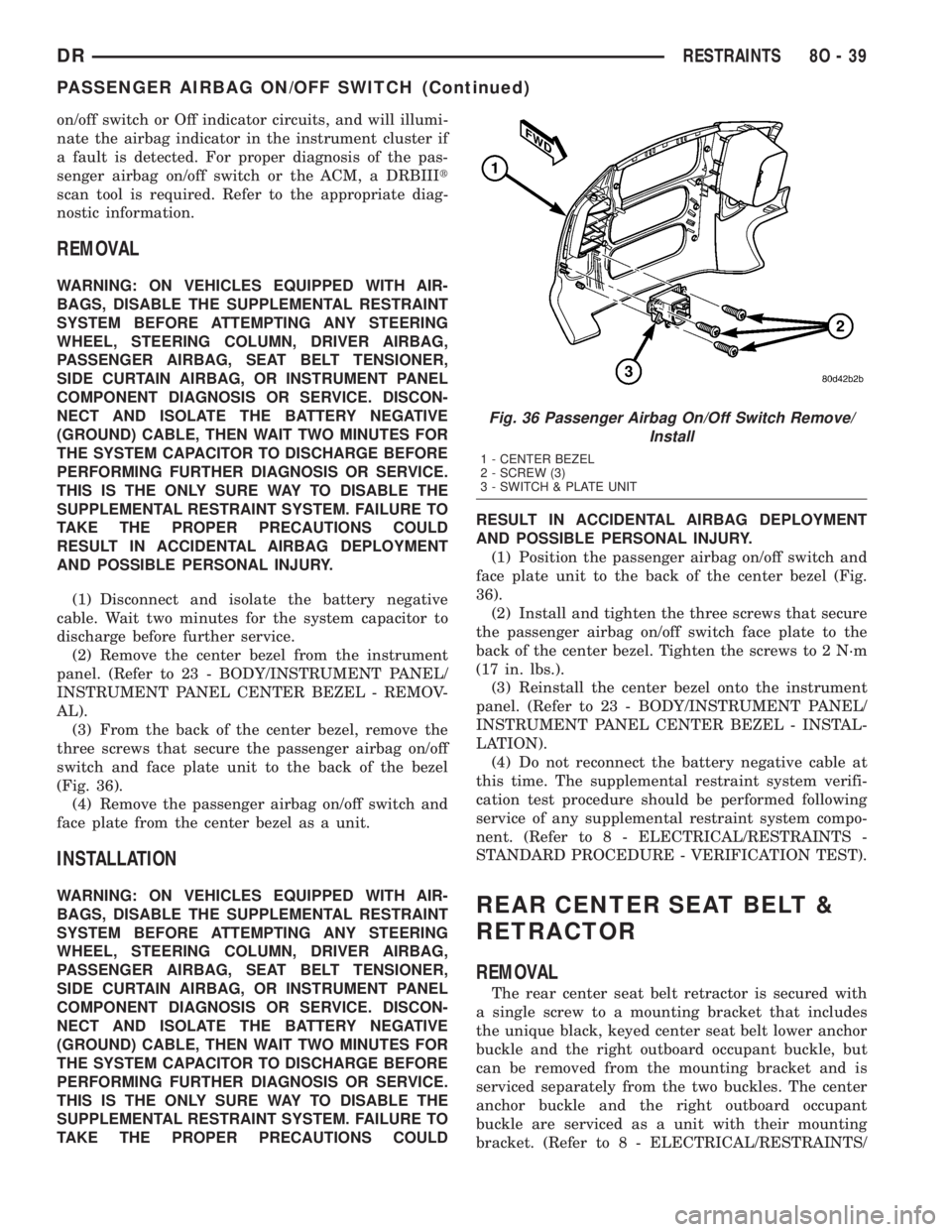
(3) From the back of the center bezel, remove the
three screws that secure the passenger airbag on/off
switch and face plate unit to the back of the bezel
(Fig. 36).
(4) Remove the passenger airbag on/off switch and
face plate from the center bezel as a unit.
INSTALLATION
WARNING: ON VEHICLES EQUIPPED WITH AIR-
BAGS, DISABLE THE SUPPLEMENTAL RESTRAINT
SYSTEM BEFORE ATTEMPTING ANY STEERING
WHEEL, STEERING COLUMN, DRIVER AIRBAG,
PASSENGER AIRBAG, SEAT BELT TENSIONER,
SIDE CURTAIN AIRBAG, OR INSTRUMENT PANEL
COMPONENT DIAGNOSIS OR SERVICE. DISCON-
NECT AND ISOLATE THE BATTERY NEGATIVE
(GROUND) CABLE, THEN WAIT TWO MINUTES FOR
THE SYSTEM CAPACITOR TO DISCHARGE BEFORE
PERFORMING FURTHER DIAGNOSIS OR SERVICE.
THIS IS THE ONLY SURE WAY TO DISABLE THE
SUPPLEMENTAL RESTRAINT SYSTEM. FAILURE TO
TAKE THE PROPER PRECAUTIONS COULDRESULT IN ACCIDENTAL AIRBAG DEPLOYMENT
AND POSSIBLE PERSONAL INJURY.
(1) Position the passenger airbag on/off switch and
face plate unit to the back of the center bezel (Fig.
36).
(2) Install and tighten the three screws that secure
the passenger airbag on/off switch face plate to the
back of the center bezel. Tighten the screws to 2 N´m
(17 in. lbs.).
(3) Reinstall the center bezel onto the instrument
panel. (Refer to 23 - BODY/INSTRUMENT PANEL/
INSTRUMENT PANEL CENTER BEZEL - INSTAL-
LATION).
(4) Do not reconnect the battery negative cable at
this time. The supplemental restraint system verifi-
cation test procedure should be performed following
service of any supplemental restraint system compo-
nent. (Refer to 8 - ELECTRICAL/RESTRAINTS -
STANDARD PROCEDURE - VERIFICATION TEST).REAR CENTER SEAT BELT &
RETRACTOR
REMOVAL
The rear center seat belt retractor is secured with
a single screw to a mounting bracket that includes
the unique black, keyed center seat belt lower anchor
buckle and the right outboard occupant buckle, but
can be removed from the mounting bracket and is
serviced separately from the two buckles. The center
anchor buckle and the right outboard occupant
buckle are serviced as a unit with their mounting
bracket. (Refer to 8 - ELECTRICAL/RESTRAINTS/
Fig. 36 Passenger Airbag On/Off Switch Remove/
Install
1 - CENTER BEZEL
2 - SCREW (3)
3 - SWITCH & PLATE UNIT
DRRESTRAINTS 8O - 39
PASSENGER AIRBAG ON/OFF SWITCH (Continued)
Page 641 of 2895
REAR SEAT BELT BUCKLE - REMOVAL - CEN-
TER ANCHOR & RIGHT OUTBOARD).
WARNING: DURING AND FOLLOWING ANY SEAT
BELT OR CHILD RESTRAINT ANCHOR SERVICE,
CAREFULLY INSPECT ALL SEAT BELTS, BUCKLES,
MOUNTING HARDWARE, RETRACTORS, TETHER
STRAPS, AND ANCHORS FOR PROPER INSTALLA-
TION, OPERATION, OR DAMAGE. REPLACE ANY
BELT THAT IS CUT, FRAYED, OR TORN.
STRAIGHTEN ANY BELT THAT IS TWISTED.
TIGHTEN ANY LOOSE FASTENERS. REPLACE ANY
BELT THAT HAS A DAMAGED OR INOPERATIVE
BUCKLE OR RETRACTOR. REPLACE ANY BELT
THAT HAS A BENT OR DAMAGED LATCH PLATE
OR ANCHOR PLATE. REPLACE ANY CHILD
RESTRAINT ANCHOR OR THE UNIT TO WHICH THE
ANCHOR IS INTEGRAL THAT HAS BEEN BENT OR
DAMAGED. NEVER ATTEMPT TO REPAIR A SEAT
BELT OR CHILD RESTRAINT COMPONENT.
ALWAYS REPLACE DAMAGED OR FAULTY SEAT
BELT AND CHILD RESTRAINT COMPONENTS WITH
THE CORRECT, NEW AND UNUSED REPLACEMENT
PARTS LISTED IN THE DAIMLERCHRYSLER MOPAR
PARTS CATALOG.
(1) Reach between the rear seat cushion and the
rear seat back to access and unbuckle the center seat
belt lower anchor latch plate from the unique black,
keyed lower anchor buckle. Use an ignition key or a
small screwdriver to depress the small white release
button on the anchor buckle.
(2) Remove the rear seat from the vehicle. On
models with the optional 60/40 split rear bench, only
the 60 percent section (right side) of the rear seat
must be removed. (Refer to 23 - BODY/SEATS/SEAT
- REAR - REMOVAL).
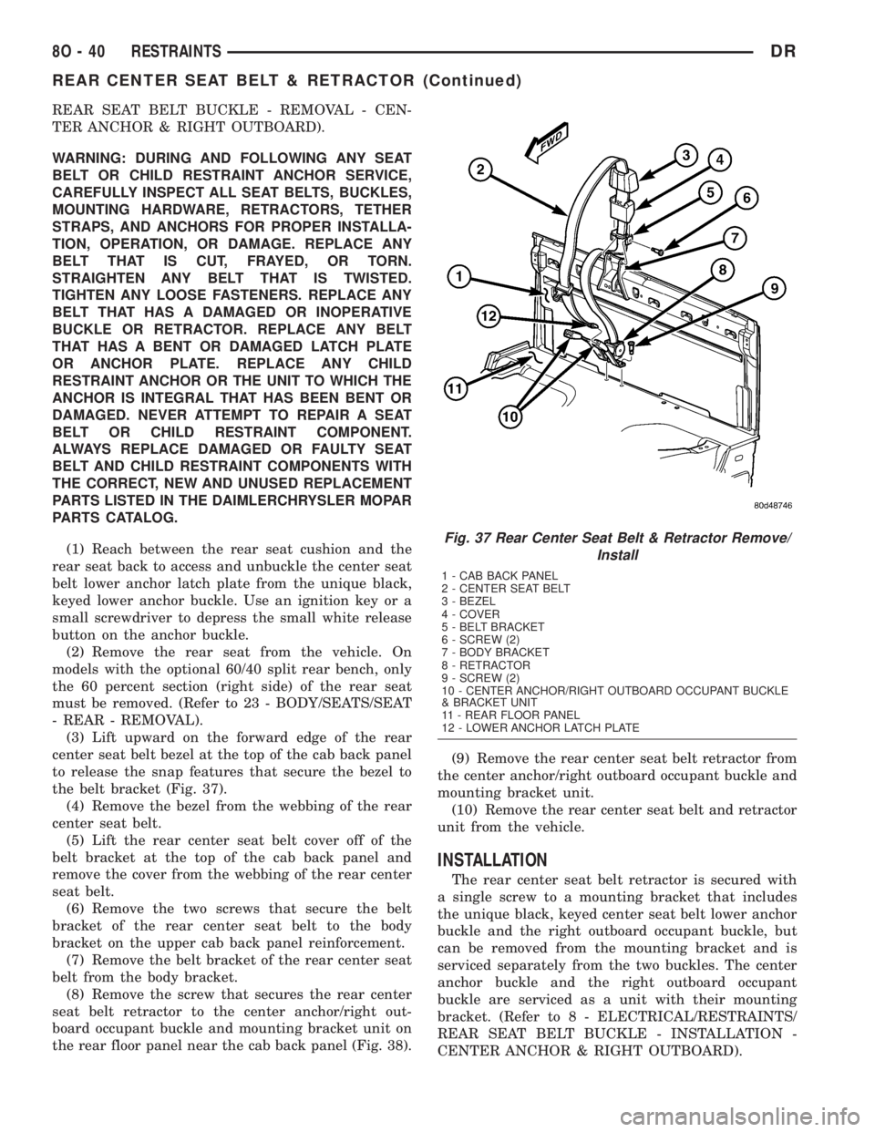
(3) Lift upward on the forward edge of the rear
center seat belt bezel at the top of the cab back panel
to release the snap features that secure the bezel to
the belt bracket (Fig. 37).
(4) Remove the bezel from the webbing of the rear
center seat belt.
(5) Lift the rear center seat belt cover off of the
belt bracket at the top of the cab back panel and
remove the cover from the webbing of the rear center
seat belt.
(6) Remove the two screws that secure the belt
bracket of the rear center seat belt to the body
bracket on the upper cab back panel reinforcement.
(7) Remove the belt bracket of the rear center seat
belt from the body bracket.
(8) Remove the screw that secures the rear center
seat belt retractor to the center anchor/right out-
board occupant buckle and mounting bracket unit on
the rear floor panel near the cab back panel (Fig. 38).(9) Remove the rear center seat belt retractor from
the center anchor/right outboard occupant buckle and
mounting bracket unit.
(10) Remove the rear center seat belt and retractor
unit from the vehicle.
INSTALLATION
The rear center seat belt retractor is secured with
a single screw to a mounting bracket that includes
the unique black, keyed center seat belt lower anchor
buckle and the right outboard occupant buckle, but
can be removed from the mounting bracket and is
serviced separately from the two buckles. The center
anchor buckle and the right outboard occupant
buckle are serviced as a unit with their mounting
bracket. (Refer to 8 - ELECTRICAL/RESTRAINTS/
REAR SEAT BELT BUCKLE - INSTALLATION -
CENTER ANCHOR & RIGHT OUTBOARD).
Fig. 37 Rear Center Seat Belt & Retractor Remove/
Install
1 - CAB BACK PANEL
2 - CENTER SEAT BELT
3 - BEZEL
4 - COVER
5 - BELT BRACKET
6 - SCREW (2)
7 - BODY BRACKET
8 - RETRACTOR
9 - SCREW (2)
10 - CENTER ANCHOR/RIGHT OUTBOARD OCCUPANT BUCKLE
& BRACKET UNIT
11 - REAR FLOOR PANEL
12 - LOWER ANCHOR LATCH PLATE
8O - 40 RESTRAINTSDR
REAR CENTER SEAT BELT & RETRACTOR (Continued)
Page 645 of 2895
les. (Refer to 8 - ELECTRICAL/RESTRAINTS/REAR
CENTER SEAT BELT & RETRACTOR - REMOVAL).
WARNING: DURING AND FOLLOWING ANY SEAT
BELT OR CHILD RESTRAINT ANCHOR SERVICE,
CAREFULLY INSPECT ALL SEAT BELTS, BUCKLES,
MOUNTING HARDWARE, RETRACTORS, TETHER
STRAPS, AND ANCHORS FOR PROPER INSTALLA-
TION, OPERATION, OR DAMAGE. REPLACE ANY
BELT THAT IS CUT, FRAYED, OR TORN.
STRAIGHTEN ANY BELT THAT IS TWISTED.
TIGHTEN ANY LOOSE FASTENERS. REPLACE ANY
BELT THAT HAS A DAMAGED OR INOPERATIVE
BUCKLE OR RETRACTOR. REPLACE ANY BELT
THAT HAS A BENT OR DAMAGED LATCH PLATE
OR ANCHOR PLATE. REPLACE ANY CHILD
RESTRAINT ANCHOR OR THE UNIT TO WHICH THE
ANCHOR IS INTEGRAL THAT HAS BEEN BENT OR
DAMAGED. NEVER ATTEMPT TO REPAIR A SEAT
BELT OR CHILD RESTRAINT COMPONENT.
ALWAYS REPLACE DAMAGED OR FAULTY SEAT
BELT AND CHILD RESTRAINT COMPONENTS WITH
THE CORRECT, NEW AND UNUSED REPLACEMENTPARTS LISTED IN THE DAIMLERCHRYSLER MOPAR
PARTS CATALOG.
(1) Reach between the rear seat cushion and the
rear seat back to access and unbuckle the rear center
seat belt lower anchor latch plate from the unique
black, keyed lower anchor buckle. Use an ignition
key or a small screwdriver to depress the small white
release button on the anchor buckle.
(2) Remove the rear seat from the vehicle. On
models with the optional 60/40 split rear bench, only
the 60 percent section (right side) of the rear seat
must be removed. (Refer to 23 - BODY/SEATS/SEAT
- REAR - REMOVAL).
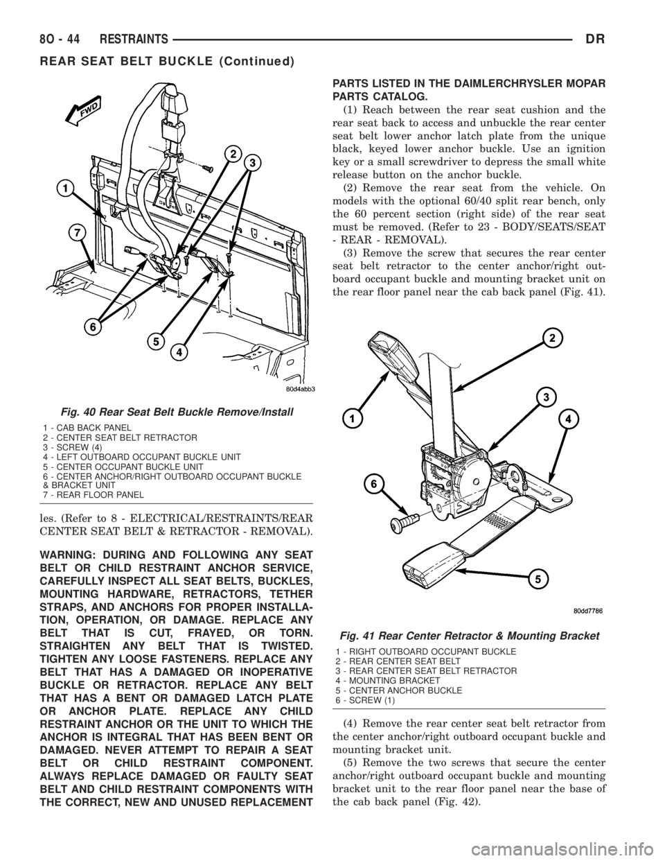
(3) Remove the screw that secures the rear center
seat belt retractor to the center anchor/right out-
board occupant buckle and mounting bracket unit on
the rear floor panel near the cab back panel (Fig. 41).
(4) Remove the rear center seat belt retractor from
the center anchor/right outboard occupant buckle and
mounting bracket unit.
(5) Remove the two screws that secure the center
anchor/right outboard occupant buckle and mounting
bracket unit to the rear floor panel near the base of
the cab back panel (Fig. 42).
Fig. 40 Rear Seat Belt Buckle Remove/Install
1 - CAB BACK PANEL
2 - CENTER SEAT BELT RETRACTOR
3 - SCREW (4)
4 - LEFT OUTBOARD OCCUPANT BUCKLE UNIT
5 - CENTER OCCUPANT BUCKLE UNIT
6 - CENTER ANCHOR/RIGHT OUTBOARD OCCUPANT BUCKLE
& BRACKET UNIT
7 - REAR FLOOR PANEL
Fig. 41 Rear Center Retractor & Mounting Bracket
1 - RIGHT OUTBOARD OCCUPANT BUCKLE
2 - REAR CENTER SEAT BELT
3 - REAR CENTER SEAT BELT RETRACTOR
4 - MOUNTING BRACKET
5 - CENTER ANCHOR BUCKLE
6 - SCREW (1)
8O - 44 RESTRAINTSDR
REAR SEAT BELT BUCKLE (Continued)
Page 646 of 2895
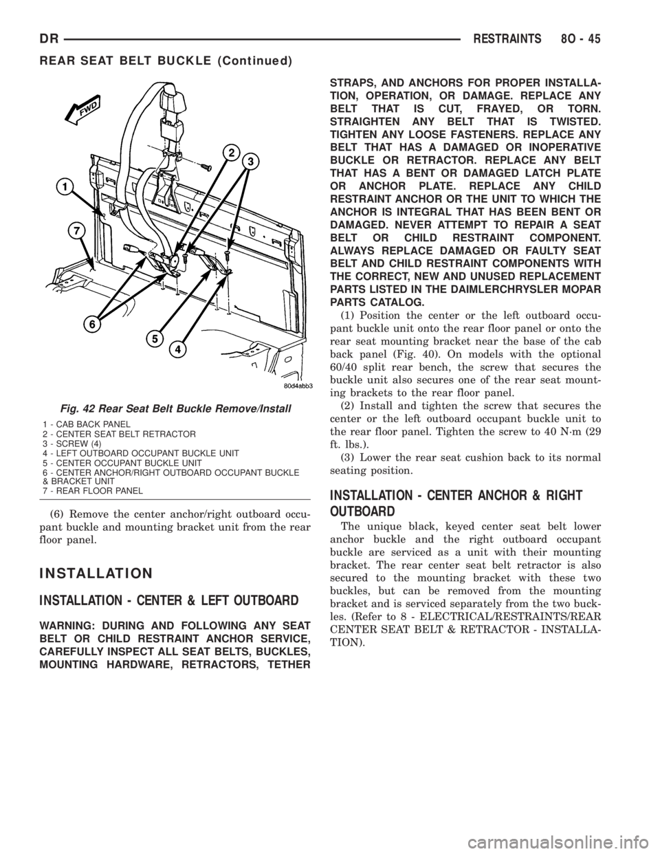
(6) Remove the center anchor/right outboard occu-
pant buckle and mounting bracket unit from the rear
floor panel.
INSTALLATION
INSTALLATION - CENTER & LEFT OUTBOARD
WARNING: DURING AND FOLLOWING ANY SEAT
BELT OR CHILD RESTRAINT ANCHOR SERVICE,
CAREFULLY INSPECT ALL SEAT BELTS, BUCKLES,
MOUNTING HARDWARE, RETRACTORS, TETHERSTRAPS, AND ANCHORS FOR PROPER INSTALLA-
TION, OPERATION, OR DAMAGE. REPLACE ANY
BELT THAT IS CUT, FRAYED, OR TORN.
STRAIGHTEN ANY BELT THAT IS TWISTED.
TIGHTEN ANY LOOSE FASTENERS. REPLACE ANY
BELT THAT HAS A DAMAGED OR INOPERATIVE
BUCKLE OR RETRACTOR. REPLACE ANY BELT
THAT HAS A BENT OR DAMAGED LATCH PLATE
OR ANCHOR PLATE. REPLACE ANY CHILD
RESTRAINT ANCHOR OR THE UNIT TO WHICH THE
ANCHOR IS INTEGRAL THAT HAS BEEN BENT OR
DAMAGED. NEVER ATTEMPT TO REPAIR A SEAT
BELT OR CHILD RESTRAINT COMPONENT.
ALWAYS REPLACE DAMAGED OR FAULTY SEAT
BELT AND CHILD RESTRAINT COMPONENTS WITH
THE CORRECT, NEW AND UNUSED REPLACEMENT
PARTS LISTED IN THE DAIMLERCHRYSLER MOPAR
PARTS CATALOG.
(1) Position the center or the left outboard occu-
pant buckle unit onto the rear floor panel or onto the
rear seat mounting bracket near the base of the cab
back panel (Fig. 40). On models with the optional
60/40 split rear bench, the screw that secures the
buckle unit also secures one of the rear seat mount-
ing brackets to the rear floor panel.
(2) Install and tighten the screw that secures the
center or the left outboard occupant buckle unit to
the rear floor panel. Tighten the screw to 40 N´m (29
ft. lbs.).
(3) Lower the rear seat cushion back to its normal
seating position.
INSTALLATION - CENTER ANCHOR & RIGHT
OUTBOARD
The unique black, keyed center seat belt lower
anchor buckle and the right outboard occupant
buckle are serviced as a unit with their mounting
bracket. The rear center seat belt retractor is also
secured to the mounting bracket with these two
buckles, but can be removed from the mounting
bracket and is serviced separately from the two buck-
les. (Refer to 8 - ELECTRICAL/RESTRAINTS/REAR
CENTER SEAT BELT & RETRACTOR - INSTALLA-
TION).
Fig. 42 Rear Seat Belt Buckle Remove/Install
1 - CAB BACK PANEL
2 - CENTER SEAT BELT RETRACTOR
3 - SCREW (4)
4 - LEFT OUTBOARD OCCUPANT BUCKLE UNIT
5 - CENTER OCCUPANT BUCKLE UNIT
6 - CENTER ANCHOR/RIGHT OUTBOARD OCCUPANT BUCKLE
& BRACKET UNIT
7 - REAR FLOOR PANEL
DRRESTRAINTS 8O - 45
REAR SEAT BELT BUCKLE (Continued)
Page 647 of 2895
WARNING: DURING AND FOLLOWING ANY SEAT
BELT OR CHILD RESTRAINT ANCHOR SERVICE,
CAREFULLY INSPECT ALL SEAT BELTS, BUCKLES,
MOUNTING HARDWARE, RETRACTORS, TETHER
STRAPS, AND ANCHORS FOR PROPER INSTALLA-
TION, OPERATION, OR DAMAGE. REPLACE ANY
BELT THAT IS CUT, FRAYED, OR TORN.
STRAIGHTEN ANY BELT THAT IS TWISTED.
TIGHTEN ANY LOOSE FASTENERS. REPLACE ANY
BELT THAT HAS A DAMAGED OR INOPERATIVE
BUCKLE OR RETRACTOR. REPLACE ANY BELT
THAT HAS A BENT OR DAMAGED LATCH PLATE
OR ANCHOR PLATE. REPLACE ANY CHILD
RESTRAINT ANCHOR OR THE UNIT TO WHICH THE
ANCHOR IS INTEGRAL THAT HAS BEEN BENT OR
DAMAGED. NEVER ATTEMPT TO REPAIR A SEAT
BELT OR CHILD RESTRAINT COMPONENT.
ALWAYS REPLACE DAMAGED OR FAULTY SEAT
BELT AND CHILD RESTRAINT COMPONENTS WITH
THE CORRECT, NEW AND UNUSED REPLACEMENT
PARTS LISTED IN THE DAIMLERCHRYSLER MOPAR
PARTS CATALOG.
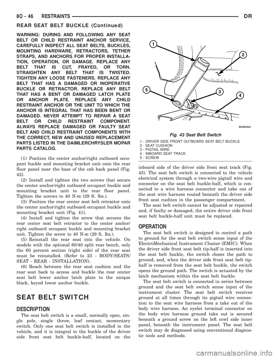
(1) Position the center anchor/right outboard occu-
pant buckle and mounting bracket unit onto the rear
floor panel near the base of the cab back panel (Fig.
42).
(2) Install and tighten the two screws that secure
the center anchor/right outboard occupant buckle and
mounting bracket unit to the rear floor panel.
Tighten the screws to 40 N´m (29 ft. lbs.).
(3) Position the rear center seat belt retractor onto
the center anchor/right outboard occupant buckle and
mounting bracket unit (Fig. 41).
(4)
Install and tighten the screw that secures the
rear center seat belt retractor to the center anchor/
right outboard occupant buckle and mounting bracket
unit. Tighten the screw to 40 N´m (29 ft. lbs.).
(5) Reinstall the rear seat into the vehicle. On
models with the optional 60/40 split rear bench, only
the 60 percent section (right side) of the rear seat
must be reinstalled. (Refer to 23 - BODY/SEATS/
SEAT - REAR - INSTALLATION).
(6) Reach between the rear seat cushion and the
rear seat back to access and buckle the rear center
seat belt lower anchor latch plate to the unique
black, keyed lower anchor buckle.
SEAT BELT SWITCH
DESCRIPTION
The seat belt switch is a small, normally open, sin-
gle pole, single throw, leaf contact, momentary
switch. Only one seat belt switch is installed in the
vehicle, and it is integral to the buckle of the driver
side front seat belt buckle-half, located on theinboard side of the driver side front seat track (Fig.
43). The seat belt switch is connected to the vehicle
electrical system through a two-wire pigtail wire and
connector on the seat belt buckle-half, which is con-
nected to a wire harness connector and take out of
the seat wire harness routed beneath the driver side
front seat cushion in the passenger compartment.
The seat belt switch cannot be adjusted or repaired
and, if faulty or damaged, the entire driver side front
seat belt buckle-half unit must be replaced.
OPERATION
The seat belt switch is designed to control a path
to ground for the seat belt switch sense input of the
ElectroMechanical Instrument Cluster (EMIC). When
the driver side front seat belt tip-half is inserted into
the seat belt buckle, the switch closes the path to
ground; and, when the driver side front seat belt tip-
half is removed from the seat belt buckle, the switch
opens the ground path. The switch is actuated by the
latch mechanism within the seat belt buckle.
The seat belt switch is connected in series between
ground and the seat belt switch sense input of the
instrument cluster. The seat belt switch receives
ground at all times through its pigtail wire connec-
tion to the seat wire harness from a take out of the
body wire harness. An eyelet terminal connector on
the body wire harness ground take out is secured
beneath a ground screw on the left cowl side inner
panel, beneath the instrument panel. The seat belt
switch may de diagnosed using conventional diagnos-
tic tools and methods.
Fig. 43 Seat Belt Switch
1 - DRIVER SIDE FRONT OUTBOARD SEAT BELT BUCKLE
2 - SEAT CUSHION
3 - PIGTAIL WIRE
4 - INBOARD SEAT TRACK
5 - SCREW
8O - 46 RESTRAINTSDR
REAR SEAT BELT BUCKLE (Continued)
Page 648 of 2895
DIAGNOSIS AND TESTING - SEAT BELT
SWITCH
Refer to the appropriate wiring information. The
wiring information includes wiring diagrams, proper
wire and connector repair procedures, details of wire
harness routing and retention, connector pin-out
information and location views for the various wire
harness connectors, splices and grounds.
WARNING: ON VEHICLES EQUIPPED WITH AIR-
BAGS, DISABLE THE SUPPLEMENTAL RESTRAINT
SYSTEM BEFORE ATTEMPTING ANY STEERING
WHEEL, STEERING COLUMN, DRIVER AIRBAG,
PASSENGER AIRBAG, SEAT BELT TENSIONER,
SIDE CURTAIN AIRBAG, OR INSTRUMENT PANEL
COMPONENT DIAGNOSIS OR SERVICE. DISCON-
NECT AND ISOLATE THE BATTERY NEGATIVE
(GROUND) CABLE, THEN WAIT TWO MINUTES FOR
THE SYSTEM CAPACITOR TO DISCHARGE BEFORE
PERFORMING FURTHER DIAGNOSIS OR SERVICE.
THIS IS THE ONLY SURE WAY TO DISABLE THE
SUPPLEMENTAL RESTRAINT SYSTEM. FAILURE TO
TAKE THE PROPER PRECAUTIONS COULD
RESULT IN ACCIDENTAL AIRBAG DEPLOYMENT
AND POSSIBLE PERSONAL INJURY.
(1) Disconnect and isolate the battery negative
cable. Disconnect the seat belt switch pigtail wire
connector from the seat wire harness connector for
the seat belt switch on the inboard side of the driver
side front seat forward of the seat belt buckle-half
anchor. Check for continuity between the seat belt
switch sense circuit and the ground circuit cavities of
the seat belt switch pigtail wire connector. There
should be continuity with the seat belt buckled, and
no continuity with the seat belt unbuckled. If OK, go
to Step 2. If not OK, replace the faulty front seat belt
buckle-half assembly.
(2) Check for continuity between the ground cir-
cuit cavity in the seat wire harness connector for the
seat belt switch and a good ground. There should be
continuity. If OK, go to Step 3. If not OK, repair the
open ground circuit to ground (G301) as required.
(3) Remove the instrument cluster from the instru-
ment panel. Check for continuity between the seat
belt switch sense circuit cavity of the seat wire har-
ness connector for the seat belt switch and a good
ground. There should be no continuity. If OK, go to
Step 4. If not OK, repair the shorted seat belt switch
sense circuit between the seat belt switch and the
instrument cluster as required.
(4) Check for continuity between the seat belt
switch sense circuit cavities of the seat wire harness
connector for the seat belt switch and the instrument
panel wire harness connector (Connector C2) for the
instrument cluster. There should be continuity. IfOK, test and replace the faulty instrument cluster as
required. (Refer to 8 - ELECTRICAL/INSTRUMENT
CLUSTER - DIAGNOSIS AND TESTING). If not OK,
repair the open seat belt switch sense circuit between
the seat belt switch and the instrument cluster as
required.
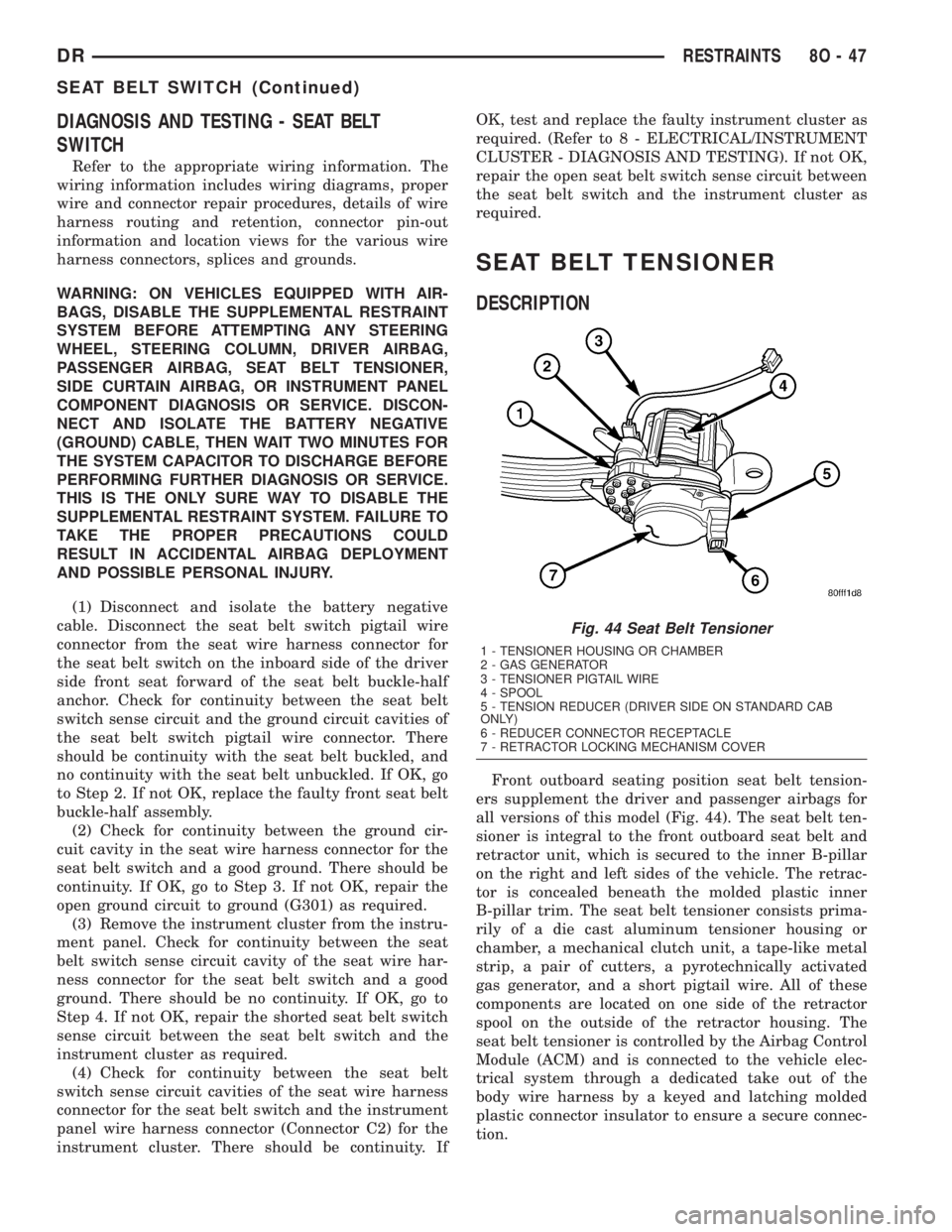
SEAT BELT TENSIONER
DESCRIPTION
Front outboard seating position seat belt tension-
ers supplement the driver and passenger airbags for
all versions of this model (Fig. 44). The seat belt ten-
sioner is integral to the front outboard seat belt and
retractor unit, which is secured to the inner B-pillar
on the right and left sides of the vehicle. The retrac-
tor is concealed beneath the molded plastic inner
B-pillar trim. The seat belt tensioner consists prima-
rily of a die cast aluminum tensioner housing or
chamber, a mechanical clutch unit, a tape-like metal
strip, a pair of cutters, a pyrotechnically activated
gas generator, and a short pigtail wire. All of these
components are located on one side of the retractor
spool on the outside of the retractor housing. The
seat belt tensioner is controlled by the Airbag Control
Module (ACM) and is connected to the vehicle elec-
trical system through a dedicated take out of the
body wire harness by a keyed and latching molded
plastic connector insulator to ensure a secure connec-
tion.
Fig. 44 Seat Belt Tensioner
1 - TENSIONER HOUSING OR CHAMBER
2 - GAS GENERATOR
3 - TENSIONER PIGTAIL WIRE
4 - SPOOL
5 - TENSION REDUCER (DRIVER SIDE ON STANDARD CAB
ONLY)
6 - REDUCER CONNECTOR RECEPTACLE
7 - RETRACTOR LOCKING MECHANISM COVER
DRRESTRAINTS 8O - 47
SEAT BELT SWITCH (Continued)