2003 DODGE RAM transmission
[x] Cancel search: transmissionPage 27 of 2895

HOISTING
STANDARD PROCEDURE - HOISTING
Refer to the Owner's Manual for emergency vehicle
lifting procedures.
WARNING: THE HOISTING AND JACK LIFTING
POINTS PROVIDED ARE FOR A COMPLETE VEHI-
CLE. WHEN A CHASSIS OR DRIVETRAIN COMPO-
NENT IS REMOVED FROM A VEHICLE, THE
CENTER OF GRAVITY IS ALTERED MAKING SOME
HOISTING CONDITIONS UNSTABLE. PROPERLY
SUPPORT (Fig. 5) OR SECURE VEHICLE TO HOIST-
ING DEVICE WHEN THESE CONDITIONS EXIST.
FLOOR JACK
When properly positioned, a floor jack can be used
to lift a vehicle (Fig. 6). Support the vehicle in the
raised position with jack stands at the front and rear
ends of the frame rails (Fig. 5).
CAUTION: Do not lift vehicle with a floor jack posi-
tioned under:
²An axle tube.
²A body side sill.
²A steering linkage component.²A drive shaft.
²The engine or transmission oil pan.
²The fuel tank.
²A front suspension arm.
NOTE: Use the correct frame rail lifting locations
only (Fig. 7) and (Fig. 8).
HOIST
A vehicle can be lifted with:
²A single-post, frame-contact hoist.
²A twin-post, chassis hoist.
²A ramp-type, drive-on hoist.
NOTE: When a frame-contact type hoist is used,
verify that the lifting pads are positioned properly
(Fig. 6). The forward lifting pads should be posi-
tioned against the forward flange of the transmis-
sion crossmember brackets at the bottom of the
frame rail (Fig. 7). The real lifting pads should be
wedged between the forward flange of the leaf
spring bracket and the frame rail (Fig. 8). Safety
stands should be placed under the frame rails at
the front and rear ends (Fig. 5).
Fig. 5 Safety Stands
1 - SAFETY STANDS
Fig. 6 Vehicle Lifting Locations
0 - 14 LUBRICATION & MAINTENANCEDR
Page 28 of 2895

TOWING
STANDARD PROCEDURE - TOWING
A vehicle equipped with SAE approved sling-type
towing equipment can be used to tow all vehicles.
When towing a 4WD vehicle using a wheel-lift towing
device, use tow dollies under the opposite end of the
vehicle. A vehicle with flat-bed device can also be
used to transport a disabled vehicle (Fig. 9).
A wooden crossbeam may be required for proper
connection when using the sling-type, front-end tow-
ing method.
SAFETY PRECAUTIONS
CAUTION: The following safety precautions must be
observed when towing a vehicle:
²Secure loose and protruding parts.
²Always use a safety chain system that is inde-
pendent of the lifting and towing equipment.
²Do not allow towing equipment to contact the
disabled vehicle's fuel tank.
²Do not allow anyone under the disabled vehicle
while it is lifted by the towing device.
²Do not allow passengers to ride in a vehicle
being towed.
²Always observe state and local laws regarding
towing regulations.
²Do not tow a vehicle in a manner that could
jeopardize the safety of the operator, pedestrians or
other motorists.
²Do not attach tow chains, T-hooks, J-hooks, or a
tow sling to a bumper, steering linkage, drive shafts
or a non-reinforced frame hole.
²Do not tow a heavily loaded vehicle. Damage to
the cab, cargo box or frame may result. Use a flatbed
device to transport a loaded vehicle.
GROUND CLEARANCE
CAUTION: If vehicle is towed with wheels removed,
install lug nuts to retain brake drums or rotors.
Fig. 7 FRONT LIFT PAD LOCATION
1 - BODY MOUNT BRACKET
2 - FRONT LIFT PAD
3 - TRANSMISSION CROSSMEMBER BRACKET
4 - FRAME RAIL
Fig. 8 REAR LIFT PAD LOCATION
1 - FRAME RAIL
2 - REAR LIFT PAD
3 - LEAF SPRING MOUNTING BRACKET
4 - BOX MOUNTING BRACKET
Fig. 9 Tow Vehicles With Approved Equipment
1 - SLING TYPE2 - WHEEL LIFT3 - FLAT BED
DRLUBRICATION & MAINTENANCE 0 - 15
HOISTING (Continued)
Page 29 of 2895

A towed vehicle should be raised until lifted wheels
are a minimum 100 mm (4 in) from the ground. Be
sure there is adequate ground clearance at the oppo-
site end of the vehicle, especially when towing over
rough terrain or steep rises in the road. If necessary,
remove the wheels from the lifted end of the vehicle
and lower the vehicle closer to the ground, to
increase the ground clearance at the opposite end of
the vehicle. Install lug nuts on wheel attaching studs
to retain brake drums or rotors.
RAMP ANGLE
If a vehicle with flat-bed towing equipment is used,
the approach ramp angle should not exceed 15
degrees.
TOWING WHEN KEYS ARE NOT AVAILABLE
When the vehicle is locked and keys are not avail-
able, use a flat bed hauler. A Wheel-lift or Sling-type
device can be used on 4WD vehicles providedall the
wheels are lifted off the ground using tow dol-
lies.
FOUR-WHEEL-DRIVE VEHICLE TOWING
Chrysler Corporation recommends that a vehicle be
transported on a flat-bed device. A Wheel-lift or
Sling-type device can be used providedall the
wheels are lifted off the ground using tow dol-
lies.
WARNING: WHEN TOWING A DISABLED VEHICLE
AND THE DRIVE WHEELS ARE SECURED IN A
WHEEL LIFT OR TOW DOLLIES, ENSURE THE
TRANSMISSION IS IN THE PARK POSITION (AUTO-
MATIC TRANSMISSION) OR A FORWARD DRIVE
GEAR (MANUAL TRANSMISSION).
CAUTION: Many vehicles are equipped with air
dams, spoilers, and/or ground effect panels. To
avoid component damage, a wheel-lift towing vehi-
cle or a flat-bed hauling vehicle is recommended.
0 - 16 LUBRICATION & MAINTENANCEDR
TOWING (Continued)
Page 63 of 2895

KNUCKLE
REMOVAL
(1) Remove the hub bearing (Refer to 2 - SUSPEN-
SION/FRONT/HUB / BEARING - REMOVAL).
(2) Remove tie-rod or drag link end from the steer-
ing knuckle arm.
(3) Remove the ABS sensor wire and bracket from
knuckle. Refer to Brakes, for proper procedures.
(4) Remove the cotter pin from the upper ball stud
nut. Remove the upper and lower ball stud nuts.
(5) Strike the steering knuckle with a brass ham-
mer to loosen.
(6) Remove knuckle from axle tube yokes.
INSTALLATION
(1) Position the steering knuckle on the ball studs.
(2) Install and tighten lower ball stud nut to 47
N´m (35 ft. lbs.) torque. Do not install cotter pin at
this time.
(3) Install and tighten upper ball stud nut to 94
N´m (70 ft. lbs.) torque. Advance nut to next slot to
line up hole and install new cotter pin.
(4) Retorque lower ball stud nut to 190±217 N´m
(140±160 ft. lbs.) torque. Advance nut to next slot to
line up hole and install new cotter pin.
(5) Install the hub bearing (Refer to 2 - SUSPEN-
SION/FRONT/HUB / BEARING - INSTALLATION).
(6) Install tie-rod or drag link end onto the steer-
ing knuckle arm.
(7) Install the ABS sensor wire and bracket to the
knuckle. Refer to Brakes, for proper procedure.
UPPER SUSPENSION ARM
REMOVAL
REMOVAL - LEFT
(1) Raise and support the vehicle.
(2) Remove the upper suspension arm nut and bolt
at the axle bracket (Fig. 16).
(3) Remove the nut and bolt at the frame rail and
remove the upper suspension arm.
REMOVAL - RIGHT
(1) Raise and support the vehicle.
(2) Disconnect the exhaust system at the mani-
folds.
(3) Disconnect the rubber exhaust mounts at the
muffler.
(4) Support the transmission.
(5) Remove the transmission cross member.
(6) Lower the exhaust system down in order to
gain access to the removal of the upper bolt.(7) Remove the nut and bolt at the frame rail and
remove the upper suspension arm.
(8) Remove the upper suspension arm nut and bolt
at the axle bracket.
(9) Remove the suspension arm from the vehicle.
INSTALLATION
INSTALLATION - LEFT
(1) Position the upper suspension arm at the axle
and frame rail.
(2) Install the bolts and finger tighten the nuts.
(3) Remove the supports and lower the vehicle.
(4) Tighten nut at the axle bracket to 163 N´m
(120 ft. lbs.). Tighten nut at frame bracket to 163
N´m (120 ft. lbs.).
INSTALLATION - RIGHT
(1) Position the upper suspension arm at the axle
and frame rail.
(2) Install the bolts, then finger tighten the nuts.
(3) Reconnect the rubber exhaust mounts at the
muffler.
(4) Reconnect the exhaust at the manifolds.
(5) Install the transmission crossmember.
(6) Remove the supports and lower the vehicle.
(7) Tighten nut at the axle bracket to 163 N´m
(120 ft. lbs.). Tighten nut at frame bracket to 163
N´m (120 ft. lbs.).
Fig. 16 Link/Coil Suspension
1 - STABILIZER BAR
2 - SHOCK ABSORBER
3 - COIL SPRING
4 - UPPER SUSPENSION ARM
5 - LOWER SUSPENSION ARM
6 - TRACK BAR
2 - 34 FRONT - LINK/COILDR
Page 76 of 2895

(15) If the vibration remains unacceptable, apply
the same steps to the front end of the propeller shaft.
(16) Install the wheel and tires. Lower the vehicle.
PROPELLER SHAFT RUNOUT
(1) Remove dirt, rust, paint and undercoating from
the propeller shaft surface where the dial indicator
will contact the shaft.
(2) The dial indicator must be installed perpendic-
ular to the shaft surface.
(3) Measure runout at the center and ends of the
shaft sufficiently far away from weld areas to ensure
that the effects of the weld process will not enter into
the measurements.
(4) Refer to Runout Specifications chart.
(5) If the propeller shaft runout is out of specifica-
tion, remove the propeller shaft, index the shaft 180É,
and re-install the propeller shaft. Measure shaft
runout again.
(6) If the propeller shaft runout is now within
specifications, mark the shaft and yokes for proper
orientation.
(7) If the propeller shaft runout is not within spec-
ifications, verify that the runout of the transmission/
transfer case and axle are within specifications.
Correct as necessary and re-measure propeller shaft
runout.
(8) Replace the propeller shaft if the runout still
exceeds the limits.
RUNOUT SPECIFICATIONS
Front of Shaft 0.020 in. (0.50 mm)
Center of Shaft 0.025 in. (0.63 mm)
Rear of Shaft 0.020 in. (0.50 mm)
note:
Measure front/rear runout approximately 3 inches (76
mm) from the weld seam at each end of the shaft
tube for tube lengths over 30 inches. For tube lengths
under 30 inches, the maximum allowed runout is
0.020 in. (0.50 mm) for the full length of the tube.
STANDARD PROCEDURE
PROPELLER SHAFT ANGLE
This procedure applies to both the front/rear pro-
peller shafts. To obtain the front output angle (A) on
the front propeller shaft, place the inclinometer the
machined surface of the C/V joint.
(1) To check driveline alignment, raise and support
the vehicle at the axles as level as possible. Allow the
wheels and propeller shaft to turn.
(2) Remove any external bearing snap rings, if
equipped from universal joint so protractor base sits
flat.
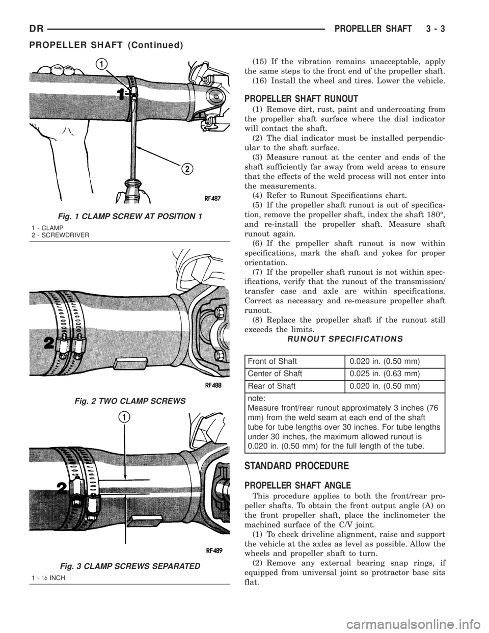
Fig. 1 CLAMP SCREW AT POSITION 1
1 - CLAMP
2 - SCREWDRIVER
Fig. 2 TWO CLAMP SCREWS
Fig. 3 CLAMP SCREWS SEPARATED
1-1¤2INCH
DRPROPELLER SHAFT 3 - 3
PROPELLER SHAFT (Continued)
Page 77 of 2895

(3) Rotate the shaft until transmission/transfer
case output yoke bearing is facing downward.
NOTE: Always make measurements from front to
rear and from the same side of the vehicle.
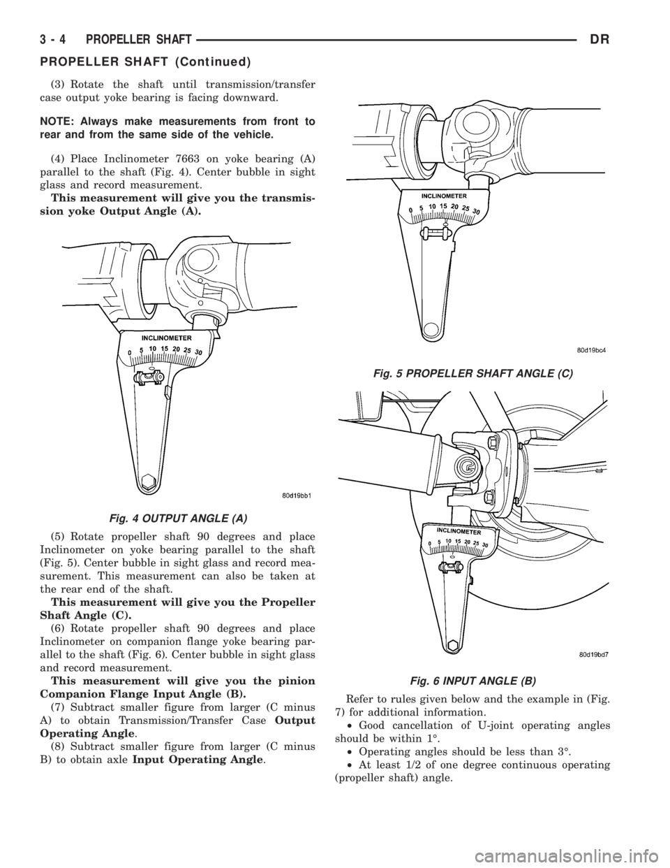
(4) Place Inclinometer 7663 on yoke bearing (A)
parallel to the shaft (Fig. 4). Center bubble in sight
glass and record measurement.
This measurement will give you the transmis-
sion yoke Output Angle (A).
(5) Rotate propeller shaft 90 degrees and place
Inclinometer on yoke bearing parallel to the shaft
(Fig. 5). Center bubble in sight glass and record mea-
surement. This measurement can also be taken at
the rear end of the shaft.
This measurement will give you the Propeller
Shaft Angle (C).
(6) Rotate propeller shaft 90 degrees and place
Inclinometer on companion flange yoke bearing par-
allel to the shaft (Fig. 6). Center bubble in sight glass
and record measurement.
This measurement will give you the pinion
Companion Flange Input Angle (B).
(7) Subtract smaller figure from larger (C minus
A) to obtain Transmission/Transfer CaseOutput
Operating Angle.
(8) Subtract smaller figure from larger (C minus
B) to obtain axleInput Operating Angle.Refer to rules given below and the example in (Fig.
7) for additional information.
²Good cancellation of U-joint operating angles
should be within 1É.
²Operating angles should be less than 3É.
²At least 1/2 of one degree continuous operating
(propeller shaft) angle.
Fig. 4 OUTPUT ANGLE (A)
Fig. 5 PROPELLER SHAFT ANGLE (C)
Fig. 6 INPUT ANGLE (B)
3 - 4 PROPELLER SHAFTDR
PROPELLER SHAFT (Continued)
Page 79 of 2895

SPECIFICATIONS
TORQUE SPECIFICATIONS
DESCRIPTION N´m Ft. Lbs. In. Lbs.
Center Bearing Bolts 54 40 -
Front Pinion Flange Bolts 115 85 -
Rear Pinion Flange Bolts 115 85 -
SPECIAL TOOLSFRONT PROPELLER SHAFT
REMOVAL
(1) Position transmission and transfer case into
neutral.
(2) Raise and support vehicle.
(3) Remove exhaust crossover pipe.
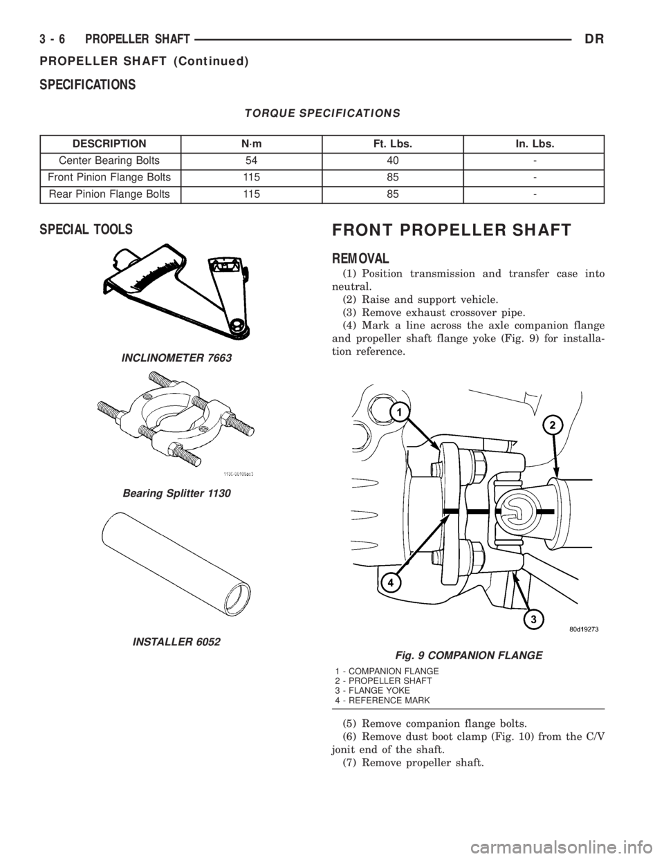
(4) Mark a line across the axle companion flange
and propeller shaft flange yoke (Fig. 9) for installa-
tion reference.
(5) Remove companion flange bolts.
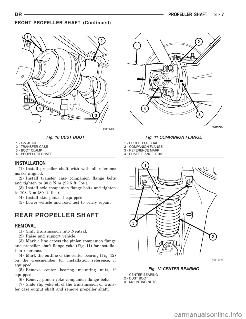
(6) Remove dust boot clamp (Fig. 10) from the C/V
jonit end of the shaft.
(7) Remove propeller shaft.
INCLINOMETER 7663
Bearing Splitter 1130
INSTALLER 6052
Fig. 9 COMPANION FLANGE
1 - COMPANION FLANGE
2 - PROPELLER SHAFT
3 - FLANGE YOKE
4 - REFERENCE MARK
3 - 6 PROPELLER SHAFTDR
PROPELLER SHAFT (Continued)
Page 80 of 2895

INSTALLATION
(1) Install propeller shaft with with all reference
marks aligned.
(2) Install transfer case companion flange bolts
and tighten to 30.5 N´m (22.5 ft. lbs.).
(3) Install axle companion flange bolts and tighten
to 108 N´m (80 ft. lbs.).
(4) Install skid plate, if equipped.
(5) Lower vehicle and road test to verify repair.
REAR PROPELLER SHAFT
REMOVAL
(1) Shift transmission into Neutral.
(2) Raise and support vehicle.
(3) Mark a line across the pinion companion flange
and propeller shaft flange yoke (Fig. 11) for installa-
tion reference.
(4) Mark the outline of the center bearing (Fig. 12)
on the crossmember for installation reference, if
equipped.
(5) Remove center bearing mounting nuts, if
equipped.
(6) Remove pinion yoke companion flange bolts.
(7) Slide slip yoke off of the transmission or trans-
fer case output shaft and remove propeller shaft.
Fig. 10 DUST BOOT
1 - C/V JOINT
2 - TRANSFER CASE
3 - BOOT CLAMP
4 - PROPELLER SHAFT
Fig. 11 COMPANION FLANGE
1 - PROPELLER SHAFT
2 - COMPANION FLANGE
3 - REFERENCE MARK
4 - SHAFT FLANGE YOKE
Fig. 12 CENTER BEARING
1 - CENTER BEARING
2 - DUST BOOT
3 - MOUNTING NUTS
DRPROPELLER SHAFT 3 - 7
FRONT PROPELLER SHAFT (Continued)