2003 DODGE RAM starter wire
[x] Cancel search: starter wirePage 440 of 2895
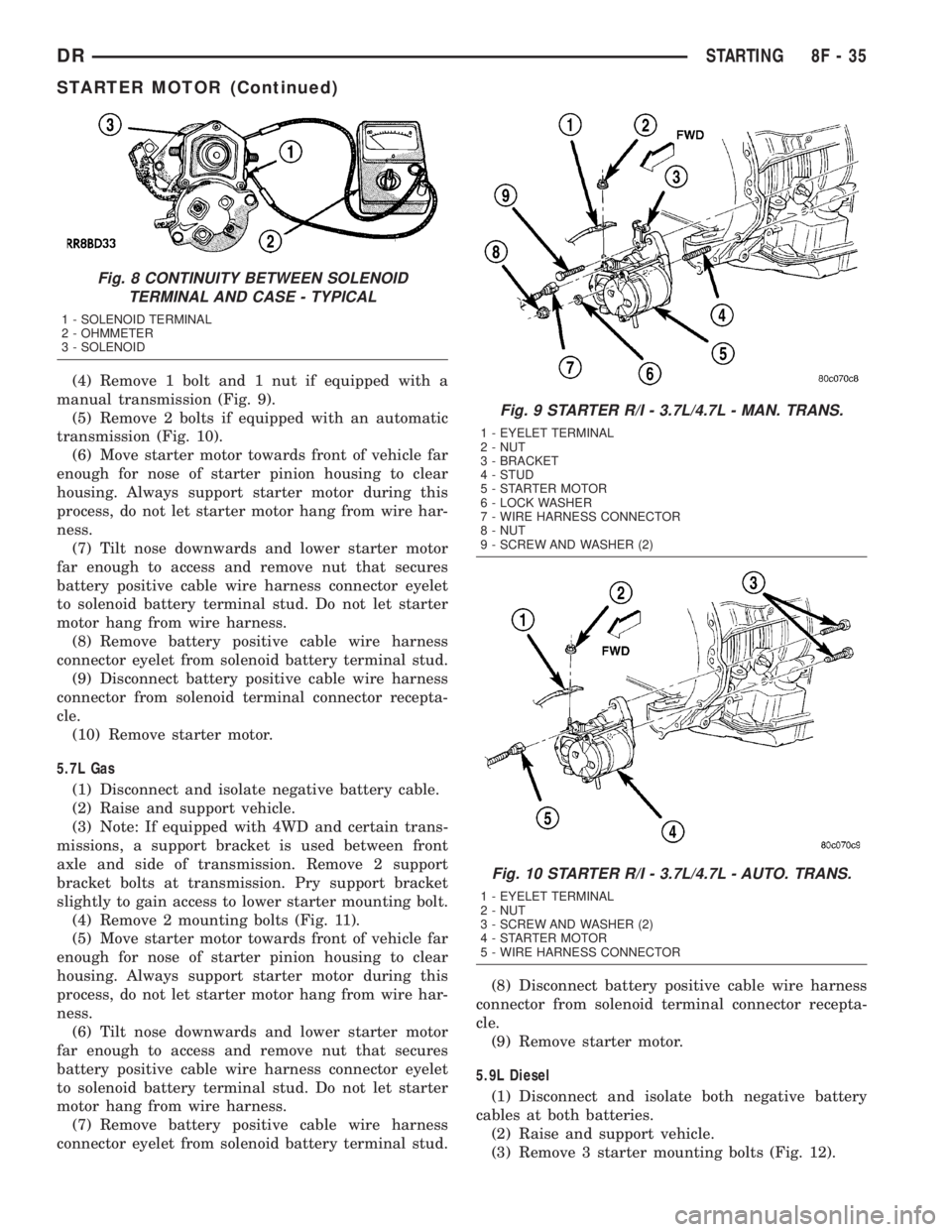
(4) Remove 1 bolt and 1 nut if equipped with a
manual transmission (Fig. 9).
(5) Remove 2 bolts if equipped with an automatic
transmission (Fig. 10).
(6) Move starter motor towards front of vehicle far
enough for nose of starter pinion housing to clear
housing. Always support starter motor during this
process, do not let starter motor hang from wire har-
ness.
(7) Tilt nose downwards and lower starter motor
far enough to access and remove nut that secures
battery positive cable wire harness connector eyelet
to solenoid battery terminal stud. Do not let starter
motor hang from wire harness.
(8) Remove battery positive cable wire harness
connector eyelet from solenoid battery terminal stud.
(9) Disconnect battery positive cable wire harness
connector from solenoid terminal connector recepta-
cle.
(10) Remove starter motor.
5.7L Gas
(1) Disconnect and isolate negative battery cable.
(2) Raise and support vehicle.
(3) Note: If equipped with 4WD and certain trans-
missions, a support bracket is used between front
axle and side of transmission. Remove 2 support
bracket bolts at transmission. Pry support bracket
slightly to gain access to lower starter mounting bolt.
(4) Remove 2 mounting bolts (Fig. 11).
(5) Move starter motor towards front of vehicle far
enough for nose of starter pinion housing to clear
housing. Always support starter motor during this
process, do not let starter motor hang from wire har-
ness.
(6) Tilt nose downwards and lower starter motor
far enough to access and remove nut that secures
battery positive cable wire harness connector eyelet
to solenoid battery terminal stud. Do not let starter
motor hang from wire harness.
(7) Remove battery positive cable wire harness
connector eyelet from solenoid battery terminal stud.(8) Disconnect battery positive cable wire harness
connector from solenoid terminal connector recepta-
cle.
(9) Remove starter motor.
5.9L Diesel
(1) Disconnect and isolate both negative battery
cables at both batteries.
(2) Raise and support vehicle.
(3) Remove 3 starter mounting bolts (Fig. 12).
Fig. 8 CONTINUITY BETWEEN SOLENOID
TERMINAL AND CASE - TYPICAL
1 - SOLENOID TERMINAL
2 - OHMMETER
3 - SOLENOID
Fig. 9 STARTER R/I - 3.7L/4.7L - MAN. TRANS.
1 - EYELET TERMINAL
2 - NUT
3 - BRACKET
4 - STUD
5 - STARTER MOTOR
6 - LOCK WASHER
7 - WIRE HARNESS CONNECTOR
8 - NUT
9 - SCREW AND WASHER (2)
Fig. 10 STARTER R/I - 3.7L/4.7L - AUTO. TRANS.
1 - EYELET TERMINAL
2 - NUT
3 - SCREW AND WASHER (2)
4 - STARTER MOTOR
5 - WIRE HARNESS CONNECTOR
DRSTARTING 8F - 35
STARTER MOTOR (Continued)
Page 441 of 2895
(4) Move starter motor towards front of vehicle far
enough for nose of starter pinion housing to clear
housing. Always support starter motor during this
process. Do not let starter motor hang from wire har-
ness.
(5) Tilt nose downwards and lower starter motor
far enough to access and remove nuts securing
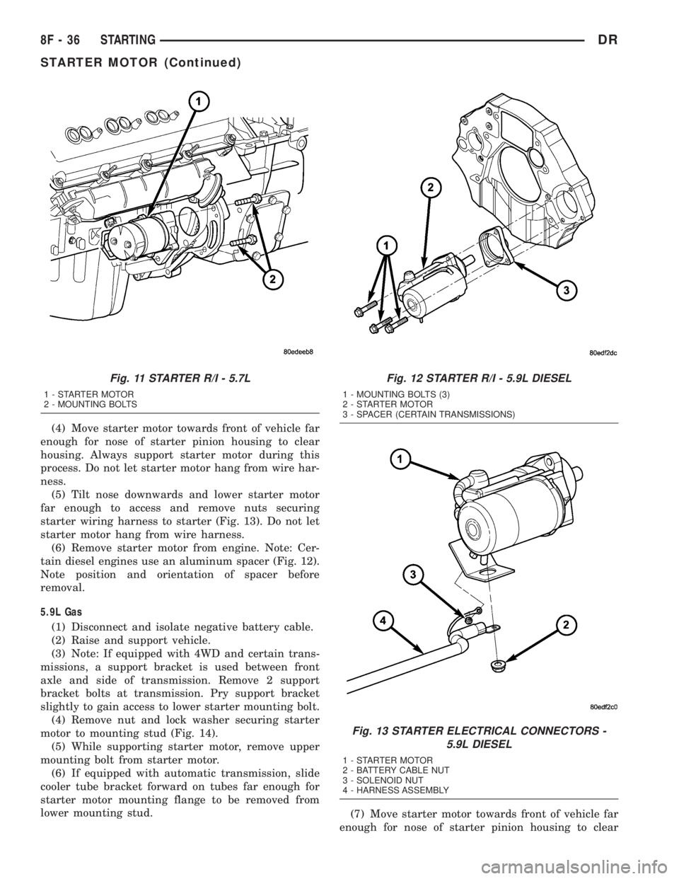
starter wiring harness to starter (Fig. 13). Do not let
starter motor hang from wire harness.
(6) Remove starter motor from engine. Note: Cer-
tain diesel engines use an aluminum spacer (Fig. 12).
Note position and orientation of spacer before
removal.
5.9L Gas
(1) Disconnect and isolate negative battery cable.
(2) Raise and support vehicle.
(3) Note: If equipped with 4WD and certain trans-
missions, a support bracket is used between front
axle and side of transmission. Remove 2 support
bracket bolts at transmission. Pry support bracket
slightly to gain access to lower starter mounting bolt.
(4) Remove nut and lock washer securing starter
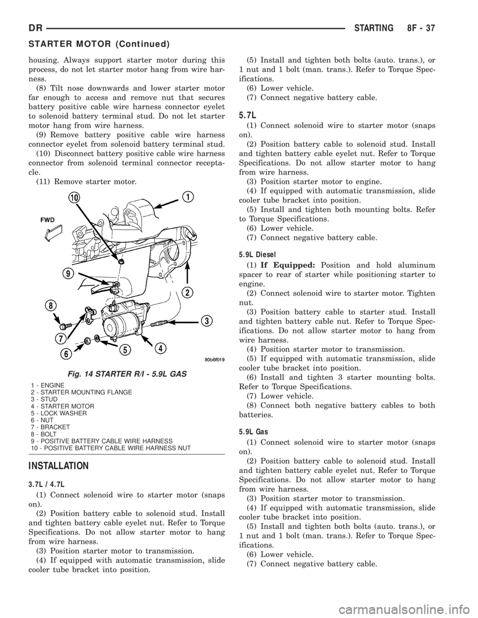
motor to mounting stud (Fig. 14).
(5) While supporting starter motor, remove upper
mounting bolt from starter motor.
(6) If equipped with automatic transmission, slide
cooler tube bracket forward on tubes far enough for
starter motor mounting flange to be removed from
lower mounting stud.
(7) Move starter motor towards front of vehicle far
enough for nose of starter pinion housing to clear
Fig. 11 STARTER R/I - 5.7L
1 - STARTER MOTOR
2 - MOUNTING BOLTS
Fig. 12 STARTER R/I - 5.9L DIESEL
1 - MOUNTING BOLTS (3)
2 - STARTER MOTOR
3 - SPACER (CERTAIN TRANSMISSIONS)
Fig. 13 STARTER ELECTRICAL CONNECTORS -
5.9L DIESEL
1 - STARTER MOTOR
2 - BATTERY CABLE NUT
3 - SOLENOID NUT
4 - HARNESS ASSEMBLY
8F - 36 STARTINGDR
STARTER MOTOR (Continued)
Page 442 of 2895
housing. Always support starter motor during this
process, do not let starter motor hang from wire har-
ness.
(8) Tilt nose downwards and lower starter motor
far enough to access and remove nut that secures
battery positive cable wire harness connector eyelet
to solenoid battery terminal stud. Do not let starter
motor hang from wire harness.
(9) Remove battery positive cable wire harness
connector eyelet from solenoid battery terminal stud.
(10) Disconnect battery positive cable wire harness
connector from solenoid terminal connector recepta-
cle.
(11) Remove starter motor.
INSTALLATION
3.7L / 4.7L
(1) Connect solenoid wire to starter motor (snaps
on).
(2) Position battery cable to solenoid stud. Install
and tighten battery cable eyelet nut. Refer to Torque
Specifications. Do not allow starter motor to hang
from wire harness.
(3) Position starter motor to transmission.
(4) If equipped with automatic transmission, slide
cooler tube bracket into position.(5) Install and tighten both bolts (auto. trans.), or
1 nut and 1 bolt (man. trans.). Refer to Torque Spec-
ifications.
(6) Lower vehicle.
(7) Connect negative battery cable.
5.7L
(1) Connect solenoid wire to starter motor (snaps
on).
(2) Position battery cable to solenoid stud. Install
and tighten battery cable eyelet nut. Refer to Torque
Specifications. Do not allow starter motor to hang
from wire harness.
(3) Position starter motor to engine.
(4) If equipped with automatic transmission, slide
cooler tube bracket into position.
(5) Install and tighten both mounting bolts. Refer
to Torque Specifications.
(6) Lower vehicle.
(7) Connect negative battery cable.
5.9L Diesel
(1)If Equipped:Position and hold aluminum
spacer to rear of starter while positioning starter to
engine.
(2) Connect solenoid wire to starter motor. Tighten
nut.
(3) Position battery cable to starter stud. Install
and tighten battery cable nut. Refer to Torque Spec-
ifications. Do not allow starter motor to hang from
wire harness.
(4) Position starter motor to transmission.
(5) If equipped with automatic transmission, slide
cooler tube bracket into position.
(6) Install and tighten 3 starter mounting bolts.
Refer to Torque Specifications.
(7) Lower vehicle.
(8) Connect both negative battery cables to both
batteries.
5.9L Gas
(1) Connect solenoid wire to starter motor (snaps
on).
(2) Position battery cable to solenoid stud. Install
and tighten battery cable eyelet nut. Refer to Torque
Specifications. Do not allow starter motor to hang
from wire harness.
(3) Position starter motor to transmission.
(4) If equipped with automatic transmission, slide
cooler tube bracket into position.
(5) Install and tighten both bolts (auto. trans.), or
1 nut and 1 bolt (man. trans.). Refer to Torque Spec-
ifications.
(6) Lower vehicle.
(7) Connect negative battery cable.
Fig. 14 STARTER R/I - 5.9L GAS
1 - ENGINE
2 - STARTER MOUNTING FLANGE
3 - STUD
4 - STARTER MOTOR
5 - LOCK WASHER
6 - NUT
7 - BRACKET
8 - BOLT
9 - POSITIVE BATTERY CABLE WIRE HARNESS
10 - POSITIVE BATTERY CABLE WIRE HARNESS NUT
DRSTARTING 8F - 37
STARTER MOTOR (Continued)
Page 697 of 2895
WIPER MODULE
DESCRIPTION
The wiper motor bracket is secured with two
screws below the wiper motor through two rubber
insulators to the bottom of the cowl plenum panel
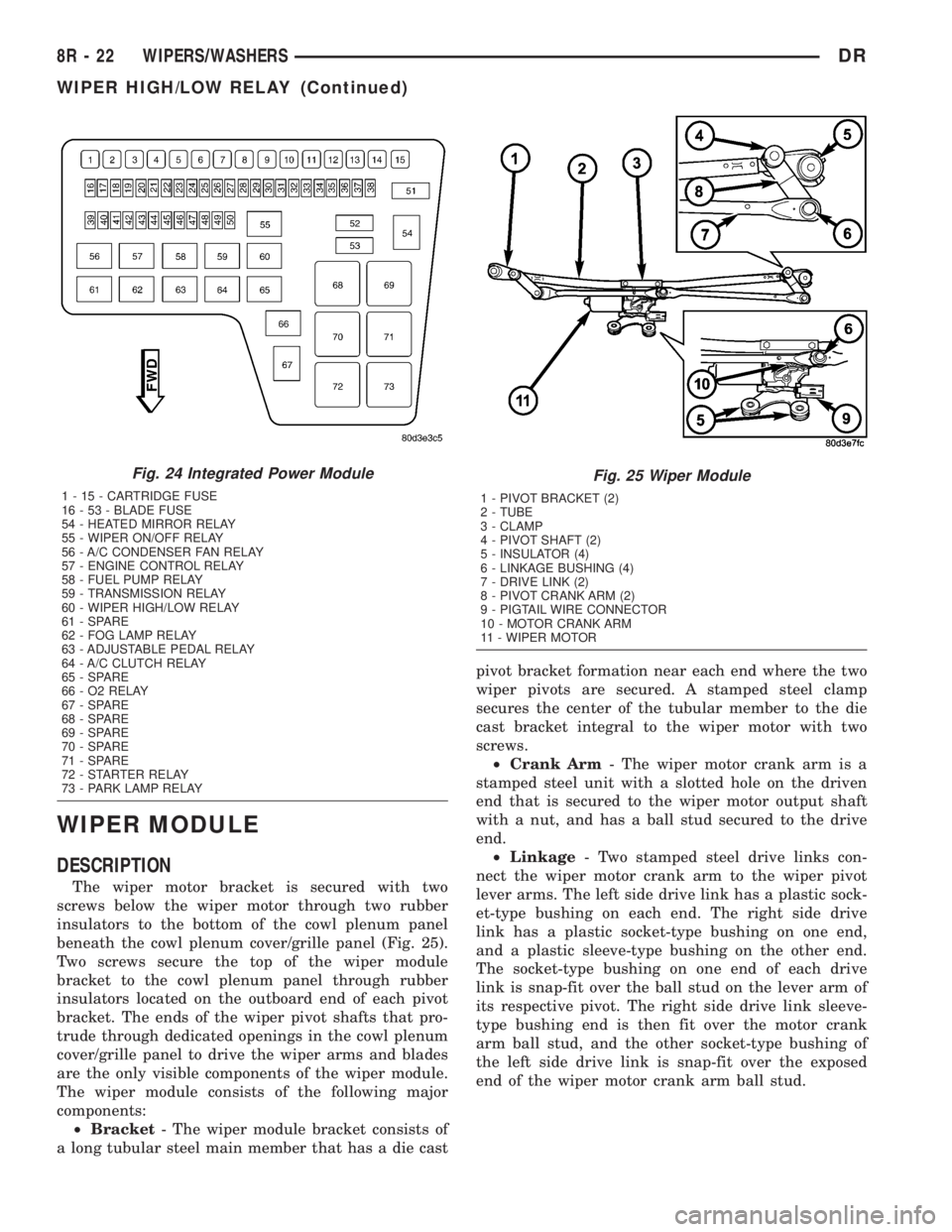
beneath the cowl plenum cover/grille panel (Fig. 25).
Two screws secure the top of the wiper module
bracket to the cowl plenum panel through rubber
insulators located on the outboard end of each pivot
bracket. The ends of the wiper pivot shafts that pro-
trude through dedicated openings in the cowl plenum
cover/grille panel to drive the wiper arms and blades
are the only visible components of the wiper module.
The wiper module consists of the following major
components:
²Bracket- The wiper module bracket consists of
a long tubular steel main member that has a die castpivot bracket formation near each end where the two
wiper pivots are secured. A stamped steel clamp
secures the center of the tubular member to the die
cast bracket integral to the wiper motor with two
screws.
²Crank Arm- The wiper motor crank arm is a
stamped steel unit with a slotted hole on the driven
end that is secured to the wiper motor output shaft
with a nut, and has a ball stud secured to the drive
end.
²Linkage- Two stamped steel drive links con-
nect the wiper motor crank arm to the wiper pivot
lever arms. The left side drive link has a plastic sock-
et-type bushing on each end. The right side drive
link has a plastic socket-type bushing on one end,
and a plastic sleeve-type bushing on the other end.
The socket-type bushing on one end of each drive
link is snap-fit over the ball stud on the lever arm of
its respective pivot. The right side drive link sleeve-
type bushing end is then fit over the motor crank
arm ball stud, and the other socket-type bushing of
the left side drive link is snap-fit over the exposed
end of the wiper motor crank arm ball stud.
Fig. 24 Integrated Power Module
1 - 15 - CARTRIDGE FUSE
16 - 53 - BLADE FUSE
54 - HEATED MIRROR RELAY
55 - WIPER ON/OFF RELAY
56 - A/C CONDENSER FAN RELAY
57 - ENGINE CONTROL RELAY
58 - FUEL PUMP RELAY
59 - TRANSMISSION RELAY
60 - WIPER HIGH/LOW RELAY
61 - SPARE
62 - FOG LAMP RELAY
63 - ADJUSTABLE PEDAL RELAY
64 - A/C CLUTCH RELAY
65 - SPARE
66 - O2 RELAY
67 - SPARE
68 - SPARE
69 - SPARE
70 - SPARE
71 - SPARE
72 - STARTER RELAY
73 - PARK LAMP RELAY
Fig. 25 Wiper Module
1 - PIVOT BRACKET (2)
2 - TUBE
3 - CLAMP
4 - PIVOT SHAFT (2)
5 - INSULATOR (4)
6 - LINKAGE BUSHING (4)
7 - DRIVE LINK (2)
8 - PIVOT CRANK ARM (2)
9 - PIGTAIL WIRE CONNECTOR
10 - MOTOR CRANK ARM
11 - WIPER MOTOR
8R - 22 WIPERS/WASHERSDR
WIPER HIGH/LOW RELAY (Continued)
Page 701 of 2895
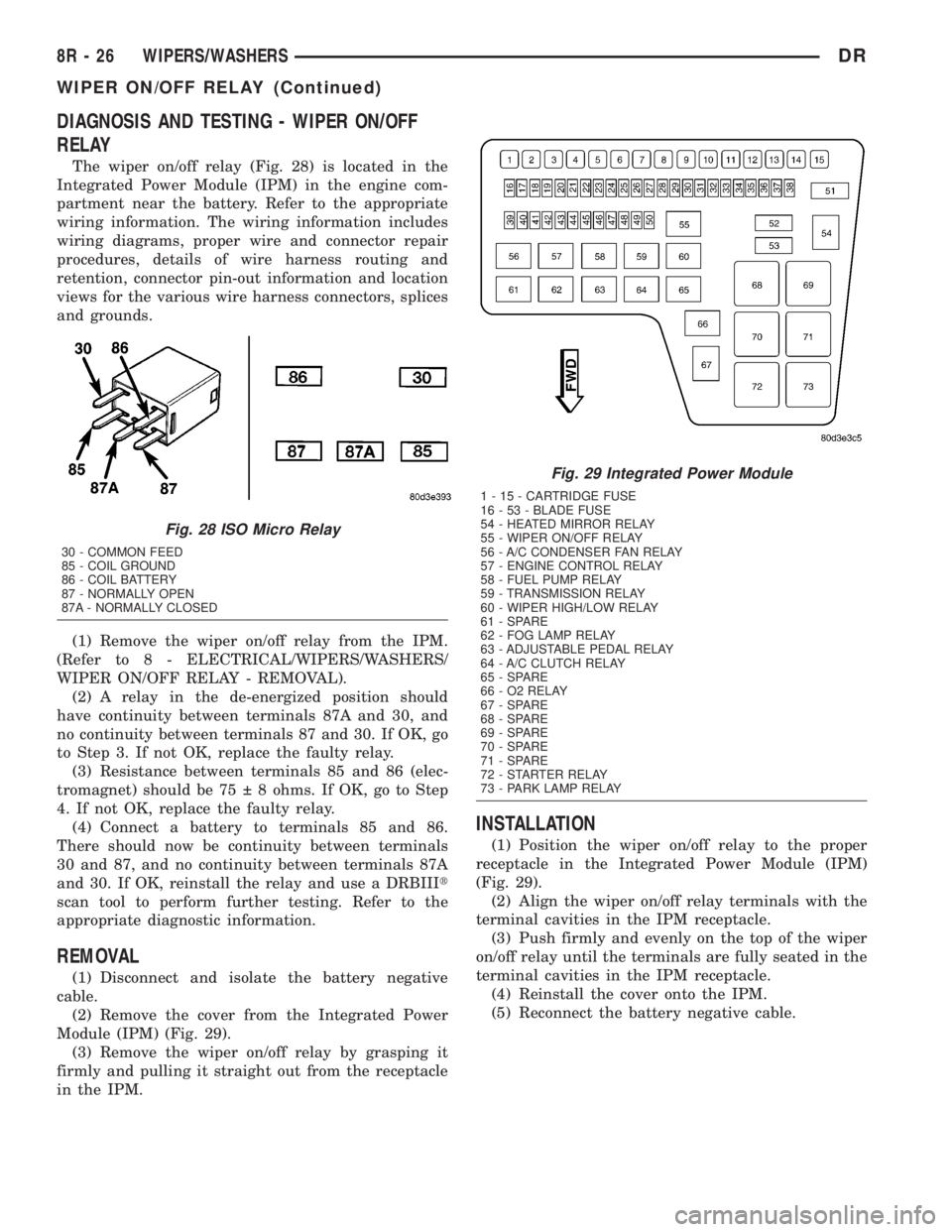
DIAGNOSIS AND TESTING - WIPER ON/OFF
RELAY
The wiper on/off relay (Fig. 28) is located in the
Integrated Power Module (IPM) in the engine com-
partment near the battery. Refer to the appropriate
wiring information. The wiring information includes
wiring diagrams, proper wire and connector repair
procedures, details of wire harness routing and
retention, connector pin-out information and location
views for the various wire harness connectors, splices
and grounds.
(1) Remove the wiper on/off relay from the IPM.
(Refer to 8 - ELECTRICAL/WIPERS/WASHERS/
WIPER ON/OFF RELAY - REMOVAL).
(2) A relay in the de-energized position should
have continuity between terminals 87A and 30, and
no continuity between terminals 87 and 30. If OK, go
to Step 3. If not OK, replace the faulty relay.
(3) Resistance between terminals 85 and 86 (elec-
tromagnet) should be 75 8 ohms. If OK, go to Step
4. If not OK, replace the faulty relay.
(4) Connect a battery to terminals 85 and 86.
There should now be continuity between terminals
30 and 87, and no continuity between terminals 87A
and 30. If OK, reinstall the relay and use a DRBIIIt
scan tool to perform further testing. Refer to the
appropriate diagnostic information.
REMOVAL
(1) Disconnect and isolate the battery negative
cable.
(2) Remove the cover from the Integrated Power
Module (IPM) (Fig. 29).
(3) Remove the wiper on/off relay by grasping it
firmly and pulling it straight out from the receptacle
in the IPM.
INSTALLATION
(1) Position the wiper on/off relay to the proper
receptacle in the Integrated Power Module (IPM)
(Fig. 29).
(2) Align the wiper on/off relay terminals with the
terminal cavities in the IPM receptacle.
(3) Push firmly and evenly on the top of the wiper
on/off relay until the terminals are fully seated in the
terminal cavities in the IPM receptacle.
(4) Reinstall the cover onto the IPM.
(5) Reconnect the battery negative cable.
Fig. 28 ISO Micro Relay
30 - COMMON FEED
85 - COIL GROUND
86 - COIL BATTERY
87 - NORMALLY OPEN
87A - NORMALLY CLOSED
Fig. 29 Integrated Power Module
1 - 15 - CARTRIDGE FUSE
16 - 53 - BLADE FUSE
54 - HEATED MIRROR RELAY
55 - WIPER ON/OFF RELAY
56 - A/C CONDENSER FAN RELAY
57 - ENGINE CONTROL RELAY
58 - FUEL PUMP RELAY
59 - TRANSMISSION RELAY
60 - WIPER HIGH/LOW RELAY
61 - SPARE
62 - FOG LAMP RELAY
63 - ADJUSTABLE PEDAL RELAY
64 - A/C CLUTCH RELAY
65 - SPARE
66 - O2 RELAY
67 - SPARE
68 - SPARE
69 - SPARE
70 - SPARE
71 - SPARE
72 - STARTER RELAY
73 - PARK LAMP RELAY
8R - 26 WIPERS/WASHERSDR
WIPER ON/OFF RELAY (Continued)
Page 1435 of 2895
STANDARD PROCEDURE
STANDARD PROCEDURE - REPAIR DAMAGED
OR WORN THREADS
CAUTION: Be sure that the tapped holes maintain
the original center line.
Damaged or worn threads can be repaired. Essen-
tially, this repair consists of:
²Drilling out worn or damaged threads.
²Tapping the hole with a special Heli-Coil Tap, or
equivalent.
²Installing an insert into the tapped hole to bring
the hole back to its original thread size.
STANDARD PROCEDUREÐHYDROSTATIC
LOCK
CAUTION: DO NOT use the starter motor to rotate
the crankshaft. Severe damage could occur.
When an engine is suspected of hydrostatic lock
(regardless of what caused the problem), follow the
steps below.
(1) Perform the Fuel Pressure Release Procedure
(Refer to 14 - FUEL SYSTEM/FUEL DELIVERY -
STANDARD PROCEDURE).
(2) Disconnect the negative cable(s) from the bat-
tery.
(3) Inspect air cleaner, induction system, and
intake manifold to ensure system is dry and clear of
foreign material.
(4) Place a shop towel around the spark plugs to
catch any fluid that may possibly be under pressure
in the cylinder head. Remove the spark plugs.
(5) With all spark plugs removed, rotate the crank-
shaft using a breaker bar and socket.
(6) Identify the fluid in the cylinders (coolant, fuel,
oil, etc.).
(7) Be sure all fluid has been removed from the
cylinders.
(8) Repair engine or components as necessary to
prevent this problem from occurring again.
(9) Squirt a small amount of engine oil into the
cylinders to lubricate the walls. This will prevent
damage on restart.
(10) Install new spark plugs. Tighten the spark
plugs to 41 N´m (30 ft. lbs.) torque.
(11) Drain engine oil. Remove and discard the oil
filter.
(12) Install the drain plug. Tighten the plug to 34
N´m (25 ft. lbs.) torque.
(13) Install a new oil filter.(14) Fill engine crankcase with the specified
amount and grade of oil. (Refer to LUBRICATION &
MAINTENANCE - SPECIFICATIONS).
(15) Connect the negative cable(s) to the battery.
(16) Start the engine and check for any leaks.
REMOVAL
(1) Disconnect the battery negative cable.
(2) Remove the air cleaner resonator and duct
work as an assembly.
(3) Drain cooling system (Refer to 7 - COOLING -
STANDARD PROCEDURE).
(4) Remove the accessory drive belt (Refer to 7 -
COOLING/ACCESSORY DRIVE/DRIVE BELTS -
REMOVAL).
(5) Remove the viscous fan/drive (Refer to 7 -
COOLING/ENGINE/RADIATOR FAN - REMOVAL).
(6) Remove radiator (Refer to 7 - COOLING/EN-
GINE/RADIATOR - REMOVAL).
(7) Remove the upper crossmember and top core
support.
NOTE: It is not necessary to drain A/C system for
engine removal.
(8) Remove the A/C compressor with the lines
attached. Secure compressor out of the way.
(9) Remove generator assembly (Refer to 8 -
ELECTRICAL/CHARGING/GENERATOR - REMOV-
AL).
(10) Perform the Fuel System Pressure Release
procedure (Refer to 14 - FUEL SYSTEM/FUEL
DELIVERY - STANDARD PROCEDURE).
(11) Remove the intake manifold and IAFM as an
assembly(Refer to 9 - ENGINE/MANIFOLDS/IN-
TAKE MANIFOLD - REMOVAL).
(12) Disconnect the heater hoses.
NOTE: It is not necessary to disconnect P/S hoses
from pump, for P/S pump removal.
(13) Remove the power steering pump and set
aside.
(14) Disconnect the fuel supply line (Refer to 14 -
FUEL SYSTEM/FUEL DELIVERY/QUICK CON-
NECT FITTING - STANDARD PROCEDURE).
(15) Raise and support the vehicle on a hoist and
drain the engine oil.
(16) Remove engine front mount thru-bolt nuts.
(17) Disconnect the transmission oil cooler lines
from their retainers at the oil pan bolts.
(18) Disconnect exhaust pipe at manifolds.
(19) Disconnect the starter wires. Remove starter
motor (Refer to 8 - ELECTRICAL/STARTING/
STARTER MOTOR - REMOVAL).
9 - 186 ENGINE - 5.7LDR
ENGINE - 5.7L (Continued)
Page 1436 of 2895
(20) Remove the structural dust cover and trans-
mission inspection cover,(Refer to 9 - ENGINE/EN-
GINE BLOCK/STRUCTURAL COVER - REMOVAL).
(21) Remove drive plate to converter bolts (Auto-
matic transmission equipped vehicles).
(22) Remove transmission bell housing to engine
block bolts.
(23) Lower the vehicle.
(24) Install engine lift fixture, special tool # 8984.
(25) Separate engine from transmission, remove
engine from vehicle, and install engine assembly on a
repair stand.
INSTALLATION
(1) Install engine lift fixture Special tool # 8984.
(2) Position the engine in the engine compartment.
(3) Lower engine into compartment and align
engine with transmission:
²Manual Transmission: Align clutch disc assem-
bly (if disturbed). Install transmission input shaft
into clutch disc while mating engine and transmis-
sion surfaces. Install two transmission to engine
block mounting bolts finger tight.
²Automatic Transmission: Mate engine and trans-
mission and install two transmission to engine block
mounting bolts finger tight.
(4) Position the thru-bolt into the support cushion
brackets.
(5) Lower engine assembly until engine mount
through bolts rest in mount perches.
(6) Install remaining transmission to engine block
mounting bolts and tighten.
(7) Tighten engine mount through bolts.
(8) Install drive plate to torque converter bolts.
(Automatic transmission models)
(9) Install the structural dust cover and transmis-
sion dust cover,(Refer to 9 - ENGINE/ENGINE
BLOCK/STRUCTURAL COVER - INSTALLATION) .
(10) Install the starter and connect the starter
wires (Refer to 8 - ELECTRICAL/STARTING/
STARTER MOTOR - INSTALLATION).
(11) Install exhaust pipe to manifold.(12) Lower the vehicle.
(13) Remove engine lift fixture, special tool # 8984.
(14) Connect the fuel supply line (Refer to 14 -
FUEL SYSTEM/FUEL DELIVERY/QUICK CON-
NECT FITTING - STANDARD PROCEDURE).
(15) Reinstall the power steering pump.
(16) Connect the heater hoses.
(17) Install the intake manifold.
(18) Using a new gasket, install throttle body
(Refer to 14 - FUEL SYSTEM/FUEL INJECTION/
THROTTLE BODY - INSTALLATION).
(19) Install the generator and wire connections
(Refer to 8 - ELECTRICAL/CHARGING/GENERA-
TOR - INSTALLATION).
(20) Install a/c compressor and lines (Refer to 24 -
HEATING & AIR CONDITIONING/PLUMBING/A/C
COMPRESSOR - INSTALLATION).
(21) Install the accessory drive belt (Refer to 7 -
COOLING/ACCESSORY DRIVE/DRIVE BELTS -
INSTALLATION).
(22) Install upper radiator support crossmember.
(23) Install radiator (Refer to 7 - COOLING/EN-
GINE/RADIATOR - INSTALLATION).
(24) Connect the radiator lower hose.
(25) Connect the transmission oil cooler lines to
the radiator.
(26) Install the fan shroud.
(27) Install the fan (Refer to 7 - COOLING/EN-
GINE/RADIATOR FAN - INSTALLATION).
(28) Connect the radiator upper hose.
(29) Install the washer bottle.
(30) Connect the transmission cooler lines.
(31) Install the air cleaner resonator and duct
work..
(32) Add engine oil to crankcase (Refer to LUBRI-
CATION & MAINTENANCE/FLUID TYPES - SPEC-
IFICATIONS).
(33) Fill cooling system (Refer to 7 - COOLING -
STANDARD PROCEDURE).
(34) Connect battery negative cable.
(35) Start engine and inspect for leaks.
(36) Road test vehicle.
DRENGINE - 5.7L 9 - 187
ENGINE - 5.7L (Continued)
Page 1483 of 2895
(3) Recover refrigerant from a/c system, if
equipped (Refer to 24 - HEATING & AIR CONDI-
TIONING/PLUMBING - STANDARD PROCEDURE).
(4) Remove the a/c condenser, if equipped (Refer to
24 - HEATING & AIR CONDITIONING/PLUMBING/
A/C CONDENSER - REMOVAL).
(5) Remove the transmission oil cooler (Refer to 7 -
COOLING/TRANSMISSION/TRANS COOLER -
REMOVAL).
(6) Remove the washer bottle from the fan shroud.
(7) Remove the viscous fan/drive (Refer to 7 -
COOLING/ENGINE/RADIATOR FAN - REMOVAL).
(8) Remove radiator (Refer to 7 - COOLING/EN-
GINE/RADIATOR - REMOVAL).
(9) Remove the upper crossmember and top core
support.
(10) Remove the accessory drive belt (Refer to 7 -
COOLING/ACCESSORY DRIVE/DRIVE BELTS -
REMOVAL).
(11) Remove the A/C compressor with the lines
attached. Secure compressor out of the way.
(12) Remove generator assembly (Refer to 8 -
ELECTRICAL/CHARGING/GENERATOR - REMOV-
AL).
(13) Remove the air cleaner resonator and duct
work as an assembly.
(14) Disconnect the throttle linkage (Refer to 14 -
FUEL SYSTEM/FUEL INJECTION/THROTTLE
CONTROL CABLE - REMOVAL).
(15) Remove throttle body (Refer to 14 - FUEL
SYSTEM/FUEL INJECTION/THROTTLE BODY -
REMOVAL).
(16) Remove the intake manifold (Refer to 9 -
ENGINE/MANIFOLDS/INTAKE MANIFOLD -
REMOVAL).
(17) Remove the distributor cap and wiring.
(18) Disconnect the heater hoses.
(19) Disconnect the power steering hoses, if
equipped.
(20) Perform the Fuel System Pressure Release
procedure (Refer to 14 - FUEL SYSTEM/FUEL
DELIVERY - STANDARD PROCEDURE).
(21) Disconnect the fuel supply line (Refer to 14 -
FUEL SYSTEM/FUEL DELIVERY/QUICK CON-
NECT FITTING - STANDARD PROCEDURE).
(22) On Manual Transmission vehicles, remove the
shift lever (Refer to 21 - TRANSMISSION/TRANS-
AXLE/MANUAL/SHIFT COVER - REMOVAL).
(23) Raise and support the vehicle on a hoist and
drain the engine oil.
(24) Remove engine front mount thru-bolt nuts.
(25) Disconnect the transmission oil cooler lines
from their retainers at the oil pan bolts.
(26) Disconnect exhaust pipe at manifolds.(27) Disconnect the starter wires. Remove starter
motor (Refer to 8 - ELECTRICAL/STARTING/
STARTER MOTOR - REMOVAL).
(28) Remove the dust shield and transmission
inspection cover.
(29) Remove drive plate to converter bolts (Auto-
matic transmission equipped vehicles).
(30) Remove transmission bell housing to engine
block bolts.
(31) Lower the vehicle.
(32) Install an engine lifting fixture.
(33) Separate engine from transmission, remove
engine from vehicle, and install engine assembly on a
repair stand.
INSTALLATION
(1) Remove engine from the repair stand and posi-
tion in the engine compartment. Position the thru-
bolt into the support cushion brackets.
(2) Install engine lifting device.
(3) Lower engine into compartment and align
engine with transmission:
²Manual Transmission: Align clutch disc assem-
bly (if disturbed). Install transmission input shaft
into clutch disc while mating engine and transmis-
sion surfaces. Install two transmission to engine
block mounting bolts finger tight.
²Automatic Transmission: Mate engine and trans-
mission and install two transmission to engine block
mounting bolts finger tight.
(4) Lower engine assembly until engine mount
through bolts rest in mount perches.
(5) Install remaining transmission to engine block
mounting bolts and tighten.
(6) Tighten engine mount through bolts.
(7) Install drive plate to torque converter bolts.
(Automatic transmission models)
(8) Install the dust shield and transmission cover.
(9) Install the starter and connect the starter
wires (Refer to 8 - ELECTRICAL/STARTING/
STARTER MOTOR - INSTALLATION).
(10) Install exhaust pipe to manifold.
(11) Install the transmission cooler line brackets to
the oil pan.
(12) Install the drain plug and tighten to 34 N´m
(25 ft. lbs.) torque.
(13) Lower the vehicle.
(14) Remove engine lifting fixture.
(15) On Manual Transmission vehicles, install the
shift lever (Refer to 21 - TRANSMISSION/TRANS-
AXLE/MANUAL/SHIFT COVER - INSTALLATION).
(16) Connect the fuel supply line (Refer to 14 -
FUEL SYSTEM/FUEL DELIVERY/QUICK CON-
NECT FITTING - STANDARD PROCEDURE).
(17) Connect the power steering hoses, if equipped.
(18) Connect the heater hoses.
9 - 234 ENGINE - 5.9LDR
ENGINE - 5.9L (Continued)