2003 DODGE RAM open gas tank
[x] Cancel search: open gas tankPage 348 of 2895
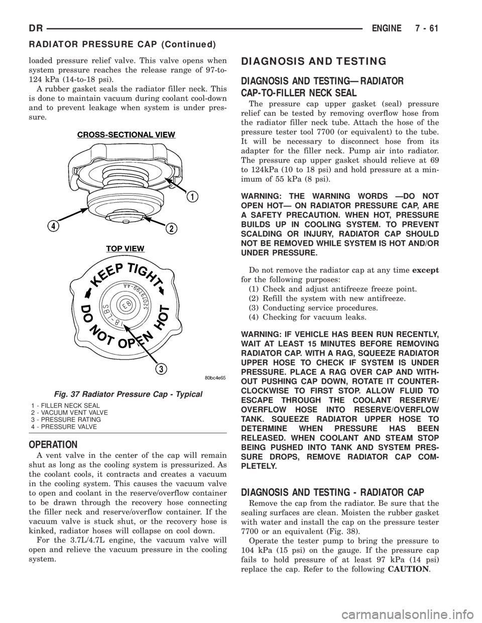
loaded pressure relief valve. This valve opens when
system pressure reaches the release range of 97-to-
124 kPa (14-to-18 psi).
A rubber gasket seals the radiator filler neck. This
is done to maintain vacuum during coolant cool-down
and to prevent leakage when system is under pres-
sure.
OPERATION
A vent valve in the center of the cap will remain
shut as long as the cooling system is pressurized. As
the coolant cools, it contracts and creates a vacuum
in the cooling system. This causes the vacuum valve
to open and coolant in the reserve/overflow container
to be drawn through the recovery hose connecting
the filler neck and reserve/overflow container. If the
vacuum valve is stuck shut, or the recovery hose is
kinked, radiator hoses will collapse on cool down.
For the 3.7L/4.7L engine, the vacuum valve will
open and relieve the vacuum pressure in the cooling
system.
DIAGNOSIS AND TESTING
DIAGNOSIS AND TESTINGÐRADIATOR
CAP-TO-FILLER NECK SEAL
The pressure cap upper gasket (seal) pressure
relief can be tested by removing overflow hose from
the radiator filler neck tube. Attach the hose of the
pressure tester tool 7700 (or equivalent) to the tube.
It will be necessary to disconnect hose from its
adapter for the filler neck. Pump air into radiator.
The pressure cap upper gasket should relieve at 69
to 124kPa (10 to 18 psi) and hold pressure at a min-
imum of 55 kPa (8 psi).
WARNING: THE WARNING WORDS ÐDO NOT
OPEN HOTÐ ON RADIATOR PRESSURE CAP, ARE
A SAFETY PRECAUTION. WHEN HOT, PRESSURE
BUILDS UP IN COOLING SYSTEM. TO PREVENT
SCALDING OR INJURY, RADIATOR CAP SHOULD
NOT BE REMOVED WHILE SYSTEM IS HOT AND/OR
UNDER PRESSURE.
Do not remove the radiator cap at any timeexcept
for the following purposes:
(1) Check and adjust antifreeze freeze point.
(2) Refill the system with new antifreeze.
(3) Conducting service procedures.
(4) Checking for vacuum leaks.
WARNING: IF VEHICLE HAS BEEN RUN RECENTLY,
WAIT AT LEAST 15 MINUTES BEFORE REMOVING
RADIATOR CAP. WITH A RAG, SQUEEZE RADIATOR
UPPER HOSE TO CHECK IF SYSTEM IS UNDER
PRESSURE. PLACE A RAG OVER CAP AND WITH-
OUT PUSHING CAP DOWN, ROTATE IT COUNTER-
CLOCKWISE TO FIRST STOP. ALLOW FLUID TO
ESCAPE THROUGH THE COOLANT RESERVE/
OVERFLOW HOSE INTO RESERVE/OVERFLOW
TANK. SQUEEZE RADIATOR UPPER HOSE TO
DETERMINE WHEN PRESSURE HAS BEEN
RELEASED. WHEN COOLANT AND STEAM STOP
BEING PUSHED INTO TANK AND SYSTEM PRES-
SURE DROPS, REMOVE RADIATOR CAP COM-
PLETELY.
DIAGNOSIS AND TESTING - RADIATOR CAP
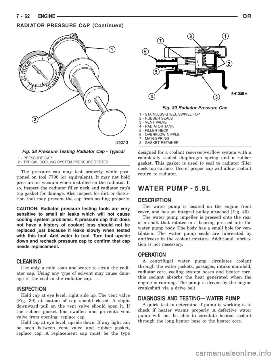
Remove the cap from the radiator. Be sure that the
sealing surfaces are clean. Moisten the rubber gasket
with water and install the cap on the pressure tester
7700 or an equivalent (Fig. 38).
Operate the tester pump to bring the pressure to
104 kPa (15 psi) on the gauge. If the pressure cap
fails to hold pressure of at least 97 kPa (14 psi)
replace the cap. Refer to the followingCAUTION.
Fig. 37 Radiator Pressure Cap - Typical
1 - FILLER NECK SEAL
2 - VACUUM VENT VALVE
3 - PRESSURE RATING
4 - PRESSURE VALVE
DRENGINE 7 - 61
RADIATOR PRESSURE CAP (Continued)
Page 349 of 2895
The pressure cap may test properly while posi-
tioned on tool 7700 (or equivalent). It may not hold
pressure or vacuum when installed on the radiator. If
so, inspect the radiator filler neck and radiator cap's
top gasket for damage. Also inspect for dirt or distor-
tion that may prevent the cap from sealing properly.
CAUTION: Radiator pressure testing tools are very
sensitive to small air leaks which will not cause
cooling system problems. A pressure cap that does
not have a history of coolant loss should not be
replaced just because it leaks slowly when tested
with this tool. Add water to tool. Turn tool upside
down and recheck pressure cap to confirm that cap
needs replacement.
CLEANING
Use only a mild soap and water to clean the radi-
ator cap. Using any type of solvent may cause dam-
age to the seal in the radiator cap.
INSPECTION
Hold cap at eye level, right side up. The vent valve
(Fig. 39) at bottom of cap should closed. A slight
downward pull on the vent valve should open it. If
the rubber gasket has swollen and prevents vent
valve from opening, replace cap.
Hold cap at eye level, upside down. If any light can
be seen between vent valve and rubber gasket,
replace cap. A replacement cap must be the typedesigned for a coolant reserve/overflow system with a
completely sealed diaphragm spring and a rubber
gasket. This gasket is used to seal to radiator filler
neck top surface. Use of proper cap will allow coolant
return to radiator.
WATER PUMP - 5.9L
DESCRIPTION
The water pump is located on the engine front
cover, and has an integral pulley attached (Fig. 40).
The water pump impeller is pressed onto the rear
of a shaft that rotates in a bearing pressed into the
water pump body. The body has a small hole for ven-
tilation. The water pump seals are lubricated by
antifreeze in the coolant mixture. Additional lubrica-
tion is not necessary.
OPERATION
A centrifugal water pump circulates coolant
through the water jackets, passages, intake manifold,
radiator core, cooling system hoses and heater core,
this coolant absorbs the heat generated when the
engine is running. The pump is driven by the engine
crankshaft via a drive belt.
DIAGNOSIS AND TESTINGÐWATER PUMP
A quick test to determine if pump is working is to
check if heater warms properly. A defective water
pump will not be able to circulate heated coolant
through the long heater hose to the heater core.
Fig. 38 Pressure Testing Radiator Cap - Typical
1 - PRESSURE CAP
2 - TYPICAL COOLING SYSTEM PRESSURE TESTER
Fig. 39 Radiator Pressure Cap
1 - STAINLESS-STEEL SWIVEL TOP
2 - RUBBER SEALS
3 - VENT VALVE
4 - RADIATOR TANK
5 - FILLER NECK
6 - OVERFLOW NIPPLE
7 - MAIN SPRING
8 - GASKET RETAINER
7 - 62 ENGINEDR
RADIATOR PRESSURE CAP (Continued)
Page 519 of 2895
OPERATION
The fuel gauge gives an indication to the vehicle
operator of the level of fuel in the fuel tank. This
gauge is controlled by the instrument cluster circuit
board based upon cluster programming and elec-
tronic messages received by the cluster from the
Powertrain Control Module (PCM) on vehicles
equipped with a gasoline engine, or from the Engine
Control Module (ECM) on vehicles equipped with a
diesel engine over the Programmable Communica-
tions Interface (PCI) data bus. The fuel gauge is an
air core magnetic unit that receives battery current
on the instrument cluster electronic circuit board
through the fused ignition switch output (run-start)
circuit whenever the ignition switch is in the On or
Start positions. The cluster is programmed to move
the gauge needle back to the low end of the scale
after the ignition switch is turned to the Off position.
The instrument cluster circuitry controls the gauge
needle position and provides the following features:
²Percent Tank Full Message- Each time the
cluster receives a message from the PCM or ECM
indicating the percent tank full, the cluster program-
ming applies an algorithm to calculate the proper
gauge needle position, then moves the gauge needle
to the proper relative position on the gauge scale.
The algorithm is used to dampen gauge needle move-
ment against the negative effect that fuel sloshing
within the fuel tank can have on accurate inputs
from the fuel tank sending unit to the PCM or ECM.
²Less Than Twenty Percent Tank Full Mes-
sage- Each time the cluster receives messages from
the PCM or ECM indicating the percent tank full is
about twenty percent or less for ten consecutive sec-
onds and the vehicle speed is zero, or for sixty con-
secutive seconds and the vehicle speed is greater
than zero, the gauge needle is moved to the one-
eighth graduation or below on the gauge scale, the
low fuel indicator is illuminated, and a single chime
tone is sounded. The low fuel indicator remains illu-
minated until the cluster receives messages from the
PCM or ECM indicating that the percent tank full is
greater than about twenty percent for ten consecu-
tive seconds and the vehicle speed is zero, or for sixty
consecutive seconds and the vehicle speed is greater
than zero, or until the ignition switch is turned to
the Off position, whichever occurs first. The chime
tone feature will only repeat during the same igni-
tion cycle if the low fuel indicator is cycled off and
then on again by the appropriate percent tank full
messages from the PCM or ECM.
²Less Than Empty Percent Tank Full Mes-
sage- Each time the cluster receives a message from
the PCM or ECM indicating the percent tank full is
less than empty, the gauge needle is moved to the far
left end of the gauge scale and the low fuel indicatoris illuminated immediately. This message would indi-
cate that the fuel tank sender input to the PCM or
ECM is a short circuit.
²More Than Full Percent Tank Full Message
- Each time the cluster receives a message from the
PCM or ECM indicating the percent tank full is more
than full, the gauge needle is moved to the far left
end of the gauge scale and the low fuel indicator is
illuminated immediately. This message would indi-
cate that the fuel tank sender input to the PCM or
ECM is an open circuit.
²Communication Error- If the cluster fails to
receive a percent tank full message, it will hold the
gauge needle at the last indication about five seconds
or until the ignition switch is turned to the Off posi-
tion, whichever occurs first. After five seconds, the
cluster will move the gauge needle to the low end of
the gauge scale.
²Actuator Test- Each time the cluster is put
through the actuator test, the fuel gauge needle will
be swept to several calibration points on the gauge
scale in a prescribed sequence in order to confirm the
functionality of the gauge and the cluster control cir-
cuitry.
On vehicles with a gasoline engine, the PCM con-
tinually monitors the fuel tank sending unit to deter-
mine the level of the fuel in the fuel tank. On
vehicles with a diesel engine, the ECM continually
monitors the fuel tank sending unit to determine the
level of the fuel in the fuel tank. The PCM or ECM
then sends the proper fuel level messages to the
instrument cluster. For further diagnosis of the fuel
gauge or the instrument cluster circuitry that con-
trols the gauge, (Refer to 8 - ELECTRICAL/INSTRU-
MENT CLUSTER - DIAGNOSIS AND TESTING).
For proper diagnosis of the fuel tank sending unit,
the PCM, the ECM, the PCI data bus, or the elec-
tronic message inputs to the instrument cluster that
control the fuel gauge, a DRBIIItscan tool is
required. Refer to the appropriate diagnostic infor-
mation.
GEAR SELECTOR INDICATOR
DESCRIPTION
An electronic automatic transmission gear selector
indicator is standard factory-installed equipment on
this model. The gear selector indicator information is
displayed in a Vacuum-Fluorescent Display (VFD)
unit. The VFD is soldered onto the cluster electronic
circuit board and is visible through a window with a
smoked clear lens located on the lower edge of the
speedometer gauge dial face of the cluster overlay.
The dark lens over the VFD prevents the indicator
from being clearly visible when it is not illuminated.
8J - 26 INSTRUMENT CLUSTERDR
FUEL GAUGE (Continued)
Page 522 of 2895
![DODGE RAM 2003 Service Repair Manual lamp, or brake lamp (excluding Center High
Mounted Stop Lamp [CHMSL]) circuit has been
detected, the lamp out indicator is illuminated. The
indicator remains illuminated until the cluster
receives a l DODGE RAM 2003 Service Repair Manual lamp, or brake lamp (excluding Center High
Mounted Stop Lamp [CHMSL]) circuit has been
detected, the lamp out indicator is illuminated. The
indicator remains illuminated until the cluster
receives a l](/manual-img/12/56913/w960_56913-521.png)
lamp, or brake lamp (excluding Center High
Mounted Stop Lamp [CHMSL]) circuit has been
detected, the lamp out indicator is illuminated. The
indicator remains illuminated until the cluster
receives a lamp out indicator lamp-off message from
the FCM or until the ignition switch is turned to the
Off position, whichever occurs first.
²Actuator Test- Each time the cluster is put
through the actuator test, the lamp out indicator will
be turned on, then off again during the VFD portion
of the test to confirm the functionality of the VFD
and the cluster control circuitry.
The FCM monitors each of the headlamp, turn sig-
nal lamp, and brake lamp (except CHMSL) circuits to
determine the condition of these exterior lamps. The
FCM then sends the proper lamp out indicator
lamp-on and lamp-off messages to the instrument
cluster. For further diagnosis of the lamp out indica-
tor or the instrument cluster circuitry that controls
the indicator, (Refer to 8 - ELECTRICAL/INSTRU-
MENT CLUSTER - DIAGNOSIS AND TESTING).
For proper diagnosis of the exterior lighting system
circuits, the FCM, the PCI data bus, or the electronic
message inputs to the instrument cluster that control
the lamp out indicator, a DRBIIItscan tool is
required. Refer to the appropriate diagnostic infor-
mation.
LOW FUEL INDICATOR
DESCRIPTION
A low fuel indicator is standard equipment on all
instrument clusters. The low fuel indicator is located
on the left side of the instrument cluster, to the left
of the fuel gauge. The low fuel indicator consists of a
stencil-like cutout of the International Control and
Display Symbol icon for ªFuelº in the opaque layer of
the instrument cluster overlay. The dark outer layer
of the overlay prevents the indicator from being
clearly visible when it is not illuminated. An amber
Light Emitting Diode (LED) behind the cutout in the
opaque layer of the overlay causes the icon to appear
in amber through the translucent outer layer of the
overlay when the indicator is illuminated from
behind by the LED, which is soldered onto the
instrument cluster electronic circuit board. The low
fuel indicator is serviced as a unit with the instru-
ment cluster.
OPERATION
The low fuel indicator gives an indication to the
vehicle operator when the level of fuel in the fuel
tank becomes low. This indicator is controlled by a
transistor on the instrument cluster circuit board
based upon cluster programming and electronic mes-sages received by the cluster from the Powertrain
Control Module (PCM) on vehicles equipped with a
gasoline engine, or from the Engine Control Module
(ECM) on vehicles equipped with a diesel engine over
the Programmable Communications Interface (PCI)
data bus. The low fuel indicator Light Emitting
Diode (LED) is completely controlled by the instru-
ment cluster logic circuit, and that logic will only
allow this indicator to operate when the instrument
cluster receives a battery current input on the fused
ignition switch output (run-start) circuit. Therefore,
the LED will always be off when the ignition switch
is in any position except On or Start. The LED only
illuminates when it is provided a path to ground by
the instrument cluster transistor. The instrument
cluster will turn on the low fuel indicator for the fol-
lowing reasons:
²Bulb Test- Each time the ignition switch is
turned to the On position the low fuel indicator is
illuminated for about two seconds as a bulb test.
²Less Than Twenty Percent Tank Full Mes-
sage- Each time the cluster receives messages from
the PCM or ECM indicating the percent tank full is
about twenty percent or less for ten consecutive sec-
onds and the vehicle speed is zero, or for sixty con-
secutive seconds and the vehicle speed is greater
than zero, the fuel gauge needle is moved to the one-
eighth graduation or below on the gauge scale, the
low fuel indicator is illuminated and a single chime
tone is sounded. The low fuel indicator remains illu-
minated until the cluster receives messages from the
PCM or ECM indicating that the percent tank full is
greater than about twenty percent for ten consecu-
tive seconds and the vehicle speed is zero, or for sixty
consecutive seconds and the vehicle speed is greater
than zero, or until the ignition switch is turned to
the Off position, whichever occurs first. The chime
tone feature will only repeat during the same igni-
tion cycle if the low fuel indicator is cycled off and
then on again by the appropriate percent tank full
messages from the PCM or ECM.
²Less Than Empty Percent Tank Full Mes-
sage- Each time the cluster receives a message from
the PCM or ECM indicating the percent tank full is
less than empty, the low fuel indicator is illuminated
immediately. This message would indicate that the
fuel tank sender input to the PCM or ECM is a short
circuit.
²More Than Full Percent Tank Full Message
- Each time the cluster receives a message from the
PCM or ECM indicating the percent tank full is more
than full, the low fuel indicator is illuminated imme-
diately. This message would indicate that the fuel
tank sender input to the PCM or ECM is an open cir-
cuit.
DRINSTRUMENT CLUSTER 8J - 29
LAMP OUT INDICATOR (Continued)
Page 1703 of 2895
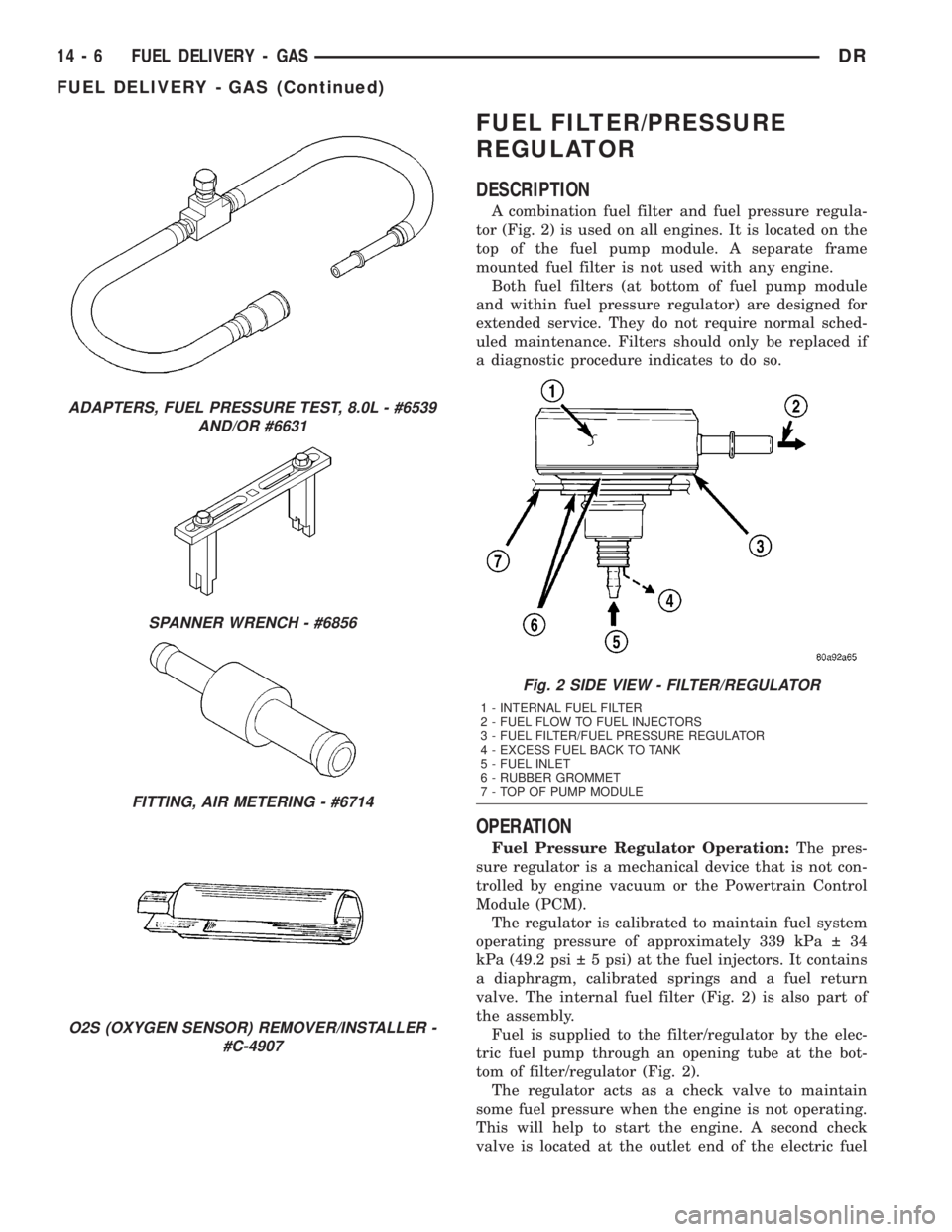
FUEL FILTER/PRESSURE
REGULATOR
DESCRIPTION
A combination fuel filter and fuel pressure regula-
tor (Fig. 2) is used on all engines. It is located on the
top of the fuel pump module. A separate frame
mounted fuel filter is not used with any engine.
Both fuel filters (at bottom of fuel pump module
and within fuel pressure regulator) are designed for
extended service. They do not require normal sched-
uled maintenance. Filters should only be replaced if
a diagnostic procedure indicates to do so.
OPERATION
Fuel Pressure Regulator Operation:The pres-
sure regulator is a mechanical device that is not con-
trolled by engine vacuum or the Powertrain Control
Module (PCM).
The regulator is calibrated to maintain fuel system
operating pressure of approximately 339 kPa 34
kPa (49.2 psi 5 psi) at the fuel injectors. It contains
a diaphragm, calibrated springs and a fuel return
valve. The internal fuel filter (Fig. 2) is also part of
the assembly.
Fuel is supplied to the filter/regulator by the elec-
tric fuel pump through an opening tube at the bot-
tom of filter/regulator (Fig. 2).
The regulator acts as a check valve to maintain
some fuel pressure when the engine is not operating.
This will help to start the engine. A second check
valve is located at the outlet end of the electric fuel
ADAPTERS, FUEL PRESSURE TEST, 8.0L - #6539
AND/OR #6631
SPANNER WRENCH - #6856
FITTING, AIR METERING - #6714
O2S (OXYGEN SENSOR) REMOVER/INSTALLER -
#C-4907
Fig. 2 SIDE VIEW - FILTER/REGULATOR
1 - INTERNAL FUEL FILTER
2 - FUEL FLOW TO FUEL INJECTORS
3 - FUEL FILTER/FUEL PRESSURE REGULATOR
4 - EXCESS FUEL BACK TO TANK
5 - FUEL INLET
6 - RUBBER GROMMET
7 - TOP OF PUMP MODULE
14 - 6 FUEL DELIVERY - GASDR
FUEL DELIVERY - GAS (Continued)
Page 1704 of 2895
pump.Refer to Fuel Pump - Description and
Operation for more information.
If fuel pressure at the pressure regulator exceeds
approximately 49.2 psi, an internal diaphragm opens
and excess fuel pressure is routed back into the tank
through the bottom of pressure regulator.
Both fuel filters (at bottom of fuel pump module
and within fuel pressure regulator) are designed for
extended service. They do not require normal sched-
uled maintenance. Filters should only be replaced if
a diagnostic procedure indicates to do so.
FUEL LEVEL SENDING UNIT /
SENSOR
DESCRIPTION
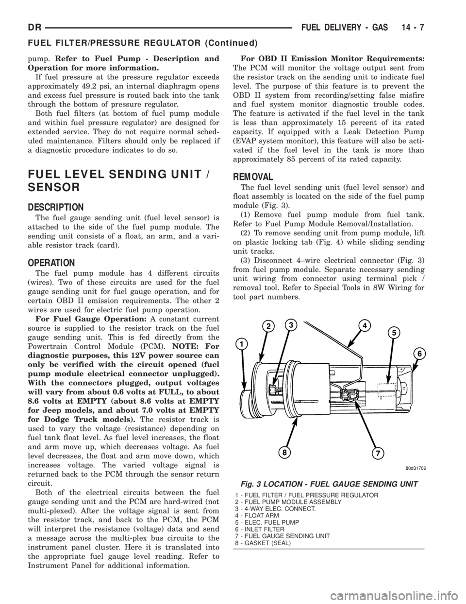
The fuel gauge sending unit (fuel level sensor) is
attached to the side of the fuel pump module. The
sending unit consists of a float, an arm, and a vari-
able resistor track (card).
OPERATION
The fuel pump module has 4 different circuits
(wires). Two of these circuits are used for the fuel
gauge sending unit for fuel gauge operation, and for
certain OBD II emission requirements. The other 2
wires are used for electric fuel pump operation.
For Fuel Gauge Operation:A constant current
source is supplied to the resistor track on the fuel
gauge sending unit. This is fed directly from the
Powertrain Control Module (PCM).NOTE: For
diagnostic purposes, this 12V power source can
only be verified with the circuit opened (fuel
pump module electrical connector unplugged).
With the connectors plugged, output voltages
will vary from about 0.6 volts at FULL, to about
8.6 volts at EMPTY (about 8.6 volts at EMPTY
for Jeep models, and about 7.0 volts at EMPTY
for Dodge Truck models).The resistor track is
used to vary the voltage (resistance) depending on
fuel tank float level. As fuel level increases, the float
and arm move up, which decreases voltage. As fuel
level decreases, the float and arm move down, which
increases voltage. The varied voltage signal is
returned back to the PCM through the sensor return
circuit.
Both of the electrical circuits between the fuel
gauge sending unit and the PCM are hard-wired (not
multi-plexed). After the voltage signal is sent from
the resistor track, and back to the PCM, the PCM
will interpret the resistance (voltage) data and send
a message across the multi-plex bus circuits to the
instrument panel cluster. Here it is translated into
the appropriate fuel gauge level reading. Refer to
Instrument Panel for additional information.For OBD II Emission Monitor Requirements:
The PCM will monitor the voltage output sent from
the resistor track on the sending unit to indicate fuel
level. The purpose of this feature is to prevent the
OBD II system from recording/setting false misfire
and fuel system monitor diagnostic trouble codes.
The feature is activated if the fuel level in the tank
is less than approximately 15 percent of its rated
capacity. If equipped with a Leak Detection Pump
(EVAP system monitor), this feature will also be acti-
vated if the fuel level in the tank is more than
approximately 85 percent of its rated capacity.
REMOVAL
The fuel level sending unit (fuel level sensor) and
float assembly is located on the side of the fuel pump
module (Fig. 3).
(1) Remove fuel pump module from fuel tank.
Refer to Fuel Pump Module Removal/Installation.
(2) To remove sending unit from pump module, lift
on plastic locking tab (Fig. 4) while sliding sending
unit tracks.
(3) Disconnect 4±wire electrical connector (Fig. 3)
from fuel pump module. Separate necessary sending
unit wiring from connector using terminal pick /
removal tool. Refer to Special Tools in 8W Wiring for
tool part numbers.
Fig. 3 LOCATION - FUEL GAUGE SENDING UNIT
1 - FUEL FILTER / FUEL PRESSURE REGULATOR
2 - FUEL PUMP MODULE ASSEMBLY
3 - 4-WAY ELEC. CONNECT.
4 - FLOAT ARM
5 - ELEC. FUEL PUMP
6 - INLET FILTER
7 - FUEL GAUGE SENDING UNIT
8 - GASKET (SEAL)
DRFUEL DELIVERY - GAS 14 - 7
FUEL FILTER/PRESSURE REGULATOR (Continued)
Page 1710 of 2895
INSTALLATION
CAUTION: Whenever the fuel pump module is ser-
viced, the rubber gasket must be replaced.
(1) Using a new gasket, position fuel pump module
into opening in fuel tank.
(2) Position locknut over top of fuel pump module.
Install locknut finger tight.
(3) Rotate module until embossed alignment arrow
(Fig. 15) points to center alignment mark. This step
must be performed to prevent float from contacting
side of fuel tank. Also be sure fitting on fuel filter/
fuel pressure regulator is pointed to drivers side of
vehicle.
(4) Install Special Tool 6856 (Fig. 16) to locknut.
(5) Tighten locknut. Refer to Torque Specifications.
(6) Install fuel tank. Refer to Fuel Tank Removal/
Installation.
FUEL RAIL
DESCRIPTION
The fuel injector rail is used to mount the fuel
injectors to the engine.
OPERATION
High pressure from the fuel pump is routed to the
fuel rail. The fuel rail then supplies the necessary
fuel to each individual fuel injector.
A quick-connect fitting with a safety latch clip is
used to attach the fuel line to the fuel rail.
The fuel rail is not repairable.
CAUTION: The left and right sections of the fuel rail
are connected with either a flexible connecting
hose, or joints. Do not attempt to separate the rail
halves at these connecting hose or joints. Due to
the design of the connecting hose or joint, it does
not use any clamps. Never attempt to install a
clamping device of any kind to the hose or joint.
When removing the fuel rail assembly for any rea-
son, be careful not to bend or kink the connecting
hose or joint.
REMOVAL
3.7L V-6
WARNING: THE FUEL SYSTEM IS UNDER CON-
STANT PRESSURE EVEN WITH ENGINE OFF.
BEFORE SERVICING FUEL RAIL, FUEL SYSTEM
PRESSURE MUST BE RELEASED.CAUTION: The left and right fuel rails are replaced
as an assembly. Do not attempt to separate rail
halves at connector tubes (Fig. 18). Due to design
of tubes, it does not use any clamps. Never attempt
to install a clamping device of any kind to tubes.
When removing fuel rail assembly for any reason,
be careful not to bend or kink tubes.
(1) Remove fuel tank filler tube cap.
(2) Perform Fuel System Pressure Release Proce-
dure.
(3) Remove negative battery cable at battery.
(4) Remove air duct at throttle body air box.
(5) Remove air box at throttle body.
(6) Remove air resonator mounting bracket at
front of throttle body (2 bolts).
(7) Disconnect fuel line latch clip and fuel line at
fuel rail. A special tool will be necessary for fuel line
disconnection. Refer to Quick-Connect Fittings.
(8) Remove necessary vacuum lines at throttle
body.
(9) Disconnect electrical connectors at all 6 fuel
injectors. To remove connector refer to (Fig. 17). Push
red colored slider away from injector (1). While push-
ing slider, depress tab (2) and remove connector (3)
from injector. The factory fuel injection wiring har-
ness is numerically tagged (INJ 1, INJ 2, etc.) for
injector position identification. If harness is not
tagged, note wiring location before removal.
(10) Disconnect electrical connectors at all throttle
body sensors.
(11) Remove 6 ignition coils. Refer to Ignition Coil
Removal/Installation.
(12) Remove 4 fuel rail mounting bolts (Fig. 18).
(13) Gently rock and pullleftside of fuel rail until
fuel injectors just start to clear machined holes in
cylinder head. Gently rock and pullrightside of rail
until injectors just start to clear cylinder head holes.
Repeat this procedure (left/right) until all injectors
have cleared cylinder head holes.
(14) Remove fuel rail (with injectors attached)
from engine.
(15) If fuel injectors are to be removed, refer to
Fuel Injector Removal/Installation.
4.7L V-8
WARNING: THE FUEL SYSTEM IS UNDER CON-
STANT PRESSURE EVEN WITH ENGINE OFF.
BEFORE SERVICING FUEL RAIL, FUEL SYSTEM
PRESSURE MUST BE RELEASED.
DRFUEL DELIVERY - GAS 14 - 13
FUEL PUMP MODULE (Continued)
Page 1717 of 2895
(13) Start engine and check for leaks.
8.0L V-10
(1) Apply a small amount of engine oil to each fuel
injector o-ring. This will help in fuel rail installation.
(2) Install injector(s) and injector clip(s) to fuel
rail.
NOTE: The fuel injector electrical connectors on all
10 injectors should be facing to right (passenger)
side of vehicle (Fig. 27).
(3) Position fuel rail/fuel injector assembly to injec-
tor openings on intake manifold.
(4) Guide each injector into intake manifold. Be
careful not to tear injector o-ring.
(5) Push therightfuel rail down until fuel injec-
tors have bottomed on injector shoulder. Push the
leftfuel rail down until fuel injectors have bottomed
on injector shoulder.
(6) Install six fuel rail mounting bolts into lower
half of intake manifold. Tighten bolts to 15 N´m (136
in. lbs.) torque.
(7) Connect electrical connectors at all fuel injec-
tors. To install connector, refer to (Fig. 26). Push con-
nector onto injector (1) and then push and lock red
colored slider (2). Verify connector is locked to injec-
tor by lightly tugging on connector. The injector wir-
ing harness is numerically tagged.
(8) Install upper half of intake manifold. Refer to
Engines for procedures.
(9) Connect main fuel line at fuel rail. Refer to
Quick-Connect Fittings for procedures.
(10) Install ignition coil pack and bracket assem-
bly at intake manifold and right engine valve cover
(four bolts).
(11) Install throttle body to intake manifold. Refer
to Throttle Body Removal / Installation.
(12) Install throttle body linkage to throttle body.
(13) Install air cleaner tube and housing.
(14) Install negative battery cable at battery.
(15) Start engine and check for leaks.
FUEL TANK
DESCRIPTION
The fuel tank is constructed of a plastic material.
Its main functions are for fuel storage and for place-
ment of the fuel pump module, and (if equipped) cer-
tain ORVR components.
OPERATION
All models pass a full 360 degree rollover test
without fuel leakage. To accomplish this, fuel and
vapor flow controls are required for all fuel tank con-
nections.Two check (control) valves are mounted into the
top of the fuel tank. Refer to Fuel Tank Check Valve
for additional information.
An evaporation control system is connected to the
fuel tank to reduce emissions of fuel vapors into the
atmosphere. When fuel evaporates from the fuel
tank, vapors pass through vent hoses or tubes to a
charcoal canister where they are temporarily held.
When the engine is running, the vapors are drawn
into the intake manifold. Certain models are also
equipped with a self-diagnosing system using a Leak
Detection Pump (LDP) and/or an On-Board Refueling
Vapor Recovery (ORVR) system. Refer to Emission
Control System for additional information.
REMOVAL- EXCEPT DIESEL
Fuel Tank Draining
WARNING: THE FUEL SYSTEM MAY BE UNDER
CONSTANT FUEL PRESSURE EVEN WITH THE
ENGINE OFF. THIS PRESSURE MUST BE
RELEASED BEFORE SERVICING FUEL TANK.
Two different procedures may be used to drain fuel
tank: through the fuel fill fitting on tank, or using
the DRBtscan tool. Due to a one-way check valve
installed into the fuel fill opening fitting at the tank,
the tank cannot be drained conventionally at the fill
cap.
The quickest draining procedure involves removing
the rubber fuel fill hose.
As an alternative procedure, the electric fuel pump
may be activated allowing tank to be drained at fuel
rail connection. Refer to DRB scan tool for fuel pump
activation procedures. Before disconnecting fuel line
at fuel rail, release fuel pressure. Refer to the Fuel
System Pressure Release Procedure for procedures.
Attach end of special test hose tool number 6541,
6539, 6631 or 6923 at fuel rail disconnection (tool
number will depend on model and/or engine applica-
tion). Position opposite end of this hose tool to an
approved gasoline draining station. Activate fuel
pump and drain tank until empty.
If electric fuel pump is not operating, fuel must be
drained through fuel fill fitting at tank. Refer to fol-
lowing procedures.
(1) Release fuel system pressure.
(2) Raise vehicle.
(3) Thoroughly clean area around fuel fill fitting
and rubber fuel fill hose at tank.
(4) If vehicle is equipped with 4 doors and a 6 foot
(short) box, remove left-rear tire/wheel.
(5) Loosen clamp (Fig. 28) and disconnect rubber
fuel fill hose at tank fitting. Using an approved gas
holding tank, drain fuel tank through this fitting.
14 - 20 FUEL DELIVERY - GASDR
FUEL RAIL (Continued)