2003 DODGE RAM auxiliary battery
[x] Cancel search: auxiliary batteryPage 1570 of 2895

(14) Install the fan support/hub assembly and
tighten bolts to 33 N´m (24 ft. lbs.) torque.
(15) Install the power steering pump.
(16) Install accessory drive belt tensioner. Torque
bolt to 43 Nm (43 ft. lbs.).
(17) Install the accessory drive belt (Refer to 7 -
COOLING/ACCESSORY DRIVE/DRIVE BELTS -
INSTALLATION).
(18) Install the charge air cooler (with a/c con-
denser and auxiliary transmission oil cooler, if
equipped) and tighten the mounting bolts to 2 N´m
(17 in. lbs.) torque.
(19) Connect charge air cooler inlet and outlet
pipes. Tighten clamps to 11 N´m (95 in. lbs.) torque.
(20) Install the radiator upper support panel.
(21) Close radiator petcock and lower the radiator
into the engine compartment. Tighten the mounting
bolts to 11 N´m (95 in. lbs.) torque.
(22) Raise vehicle on hoist.
(23)
Connect radiator lower hose and install clamp.
(24) Connect transmission auxiliary oil cooler lines
(if equipped).
(25) Lower vehicle.
(26) Install the fan shroud and tighten the mount-
ing screws to 6 N´m (50 in. lbs.) torque.
(27) Install the electronically controlled viscous
fan/drive assembly. Connect harness connector.(Refer
to 7 - COOLING/ENGINE/RADIATOR FAN -
INSTALLATION).
(28) Install the coolant recovery and windshield
washer fluid reservoirs to the fan shroud.
(29) Connect the coolant recovery hose to the radi-
ator filler neck.
(30) Add engine coolant (Refer to 7 - COOLING -
STANDARD PROCEDURE).
(31) Charge A/C system with refrigerant (if A/C
equipped) (Refer to 24 - HEATING & AIR CONDI-
TIONING/PLUMBING - STANDARD PROCEDURE).
(32) Connect the battery negative cables.
(33) Start engine and check for engine oil and cool-
ant leaks.
CONNECTING ROD BEARINGS
STANDARD PROCEDURE - CONNECTING ROD
BEARING AND CRANKSHAFT JOURNAL
CLEARANCE
(1) Measure the connecting rod bore with bearings
removedand the bolts tightened to 100 N´m (73 ft.
lbs.) torque..
(2) Measure the connecting rod bore with the bear-
ingsinstalledand the bolts tightened to 100 N´m
(73 ft. lbs.) torque.
Measure within 20É arc from each side of the part-
ing line. Also measure 90É from parting line.Record the smallest and largest diameter.
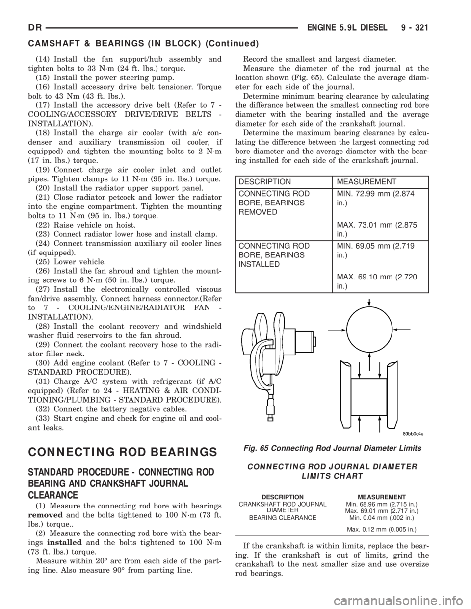
Measure the diameter of the rod journal at the
location shown (Fig. 65). Calculate the average diam-
eter for each side of the journal.
Determine minimum bearing clearance by calculating
the differance between the smallest connecting rod bore
diameter with the bearing installed and the average
diameter for each side of the crankshaft journal.
Determine the maximum bearing clearance by calcu-
lating the difference between the largest connecting rod
bore diameter and the average diameter with the bear-
ing installed for each side of the crankshaft journal.
DESCRIPTION MEASUREMENT
CONNECTING ROD
BORE, BEARINGS
REMOVEDMIN. 72.99 mm (2.874
in.)
MAX. 73.01 mm (2.875
in.)
CONNECTING ROD
BORE, BEARINGS
INSTALLEDMIN. 69.05 mm (2.719
in.)
MAX. 69.10 mm (2.720
in.)
If the crankshaft is within limits, replace the bear-
ing. If the crankshaft is out of limits, grind the
crankshaft to the next smaller size and use oversize
rod bearings.
Fig. 65 Connecting Rod Journal Diameter Limits
CONNECTING ROD JOURNAL DIAMETER
LIMITS CHART
DESCRIPTION MEASUREMENT
CRANKSHAFT ROD JOURNAL
DIAMETERMin. 68.96 mm (2.715 in.)
Max. 69.01 mm (2.717 in.)
BEARING CLEARANCE Min. 0.04 mm (.002 in.)
Max. 0.12 mm (0.005 in.)
DRENGINE 5.9L DIESEL 9 - 321
CAMSHAFT & BEARINGS (IN BLOCK) (Continued)
Page 1671 of 2895

(1) Disconnect the battery negative cables.
(2) Discharge the A/C system (Refer to 24 - HEAT-
ING & AIR CONDITIONING/PLUMBING - STAN-
DARD PROCEDURE) and remove the A/C condenser
(Refer to 24 - HEATING & AIR CONDITIONING/
PLUMBING/A/C CONDENSER - REMOVAL) (if A/C
equipped).
(3) Remove the transmission auxiliary cooler
(Refer to 7 - COOLING/TRANSMISSION/TRANS
COOLER - REMOVAL).
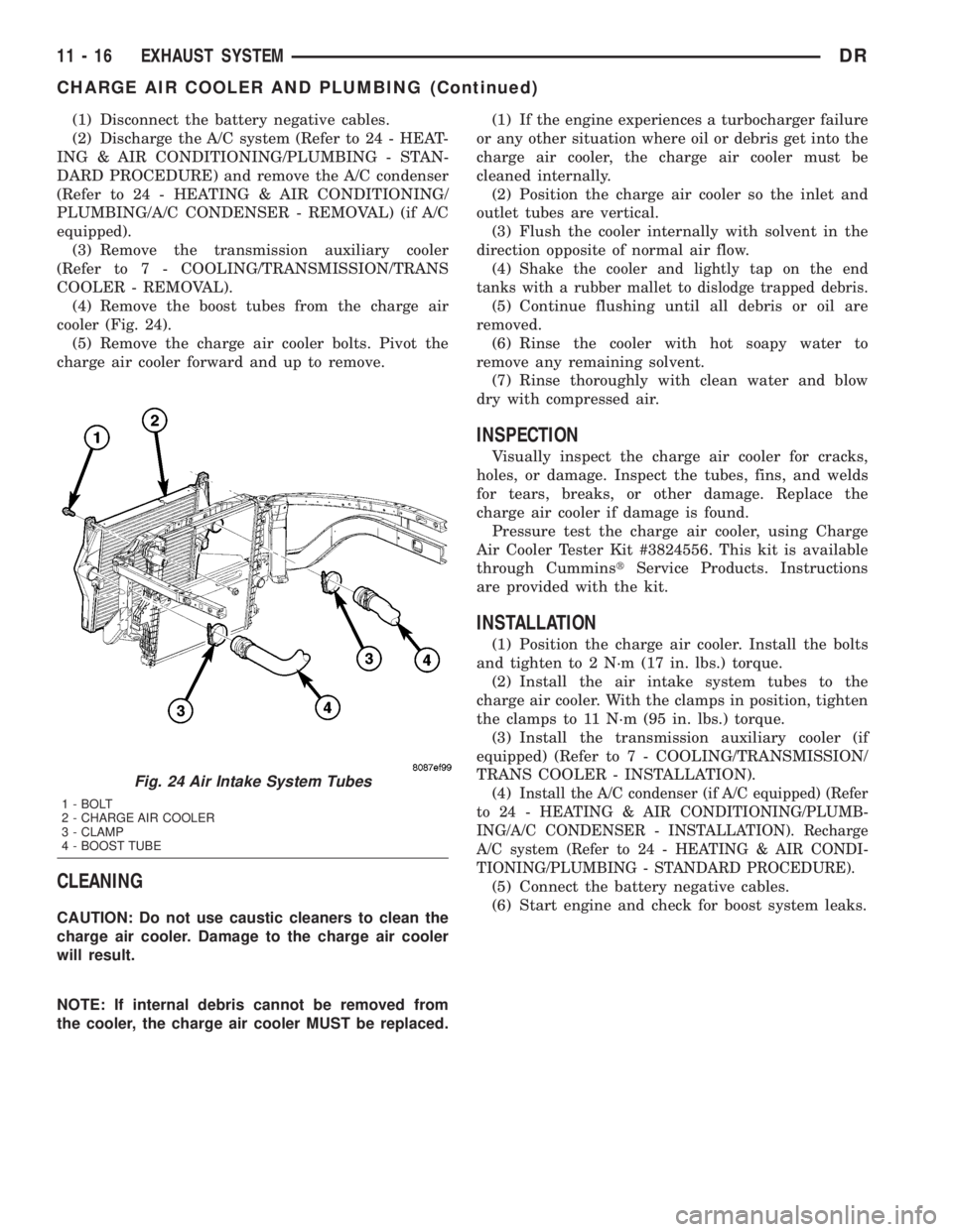
(4) Remove the boost tubes from the charge air
cooler (Fig. 24).
(5) Remove the charge air cooler bolts. Pivot the
charge air cooler forward and up to remove.
CLEANING
CAUTION: Do not use caustic cleaners to clean the
charge air cooler. Damage to the charge air cooler
will result.
NOTE: If internal debris cannot be removed from
the cooler, the charge air cooler MUST be replaced.(1) If the engine experiences a turbocharger failure
or any other situation where oil or debris get into the
charge air cooler, the charge air cooler must be
cleaned internally.
(2) Position the charge air cooler so the inlet and
outlet tubes are vertical.
(3) Flush the cooler internally with solvent in the
direction opposite of normal air flow.
(4)
Shake the cooler and lightly tap on the end
tanks with a rubber mallet to dislodge trapped debris.
(5) Continue flushing until all debris or oil are
removed.
(6) Rinse the cooler with hot soapy water to
remove any remaining solvent.
(7) Rinse thoroughly with clean water and blow
dry with compressed air.
INSPECTION
Visually inspect the charge air cooler for cracks,
holes, or damage. Inspect the tubes, fins, and welds
for tears, breaks, or other damage. Replace the
charge air cooler if damage is found.
Pressure test the charge air cooler, using Charge
Air Cooler Tester Kit #3824556. This kit is available
through CumminstService Products. Instructions
are provided with the kit.
INSTALLATION
(1) Position the charge air cooler. Install the bolts
and tighten to 2 N´m (17 in. lbs.) torque.
(2) Install the air intake system tubes to the
charge air cooler. With the clamps in position, tighten
the clamps to 11 N´m (95 in. lbs.) torque.
(3) Install the transmission auxiliary cooler (if
equipped) (Refer to 7 - COOLING/TRANSMISSION/
TRANS COOLER - INSTALLATION).
(4)
Install the A/C condenser (if A/C equipped) (Refer
to 24 - HEATING & AIR CONDITIONING/PLUMB-
ING/A/C CONDENSER - INSTALLATION). Recharge
A/C system (Refer to 24 - HEATING & AIR CONDI-
TIONING/PLUMBING - STANDARD PROCEDURE).
(5) Connect the battery negative cables.
(6) Start engine and check for boost system leaks.
Fig. 24 Air Intake System Tubes
1 - BOLT
2 - CHARGE AIR COOLER
3 - CLAMP
4 - BOOST TUBE
11 - 16 EXHAUST SYSTEMDR
CHARGE AIR COOLER AND PLUMBING (Continued)
Page 2860 of 2895

BRAKE SYSTEM - DIAGNOSIS AND
TESTING, BASE........................5-2
BRAKE TRANSMISSION SHIFT
INTERLOCK - ADJUSTMENTS . . . 21-195,21-376,
21-540
BRAKE TRANSMISSION SHIFT
INTERLOCK - DIAGNOSIS AND
TESTING..............21-195,21-375,21-540
BRAKE TRANSMISSION SHIFT
INTERLOCK SYSTEM - DESCRIPTION . . . 21-194,
21-375,21-540
BRAKE TRANSMISSION SHIFT
INTERLOCK SYSTEM - OPERATION.....21-194,
21-375,21-540
BRAKE/PARK BRAKE INDICATOR -
DESCRIPTION.......................8J-18
BRAKE/PARK BRAKE INDICATOR -
OPERATION.........................8J-19
BRAKES - ABS - DESCRIPTION...........5-39
BRAKES - ABS - OPERATION............5-39
BRAKES, SPECIAL TOOLS - BASE.........5-5
BREAK-IN - STANDARD PROCEDURE,
A/C COMPRESSOR CLUTCH............24-10
BREATHER - INSTALLATION,
CRANKCASE........................9-292
BREATHER - REMOVAL, CRANKCASE.....9-291
BUCKLE - INSTALLATION, FRONT
OUTBOARD SEAT BELT................8O-34
BUCKLE - REMOVAL, FRONT OUTBOARD
SEAT BELT .........................8O-33
BUILT-IN INDICATOR TEST - STANDARD
PROCEDURE........................8F-10
BUMPER - INSTALLATION, FRONT........13-2
BUMPER - INSTALLATION, JOUNCE.......2-40
BUMPER - INSTALLATION, REAR.........13-4
BUMPER - REMOVAL, FRONT............13-2
BUMPER - REMOVAL, JOUNCE...........2-40
BUMPER - REMOVAL, REAR.............13-4
BUMPERS (3500) - INSTALLATION,
AUXILIARY SPRING....................2-40
BUMPERS (3500) - REMOVAL,
AUXILIARY SPRING....................2-40
BURNT FLUID - DIAGNOSIS AND
TESTING, CAUSES OF....21-201,21-381,21-541
BUSHING - INSTALLATION.............19-18
BUSHING - INSTALLATION,
DISTRIBUTOR.......................9-258
BUSHING - INSTALLATION, EXTENSION
HOUSING..........................21-200
BUSHING - INSTALLATION, TORSION
BAR CROSS MEMBER..................2-14
BUSHING - REMOVAL.................19-18
BUSHING - REMOVAL, DISTRIBUTOR.....9-258
BUSHING - REMOVAL, EXTENSION
HOUSING..........................21-200
BUSHING - REMOVAL, TORSION BAR
CROSSMEMBER......................2-12
BUSHING AND SEAL - INSTALLATION,
EXTENSION HOUSING..........21-616,21-682
BUSHING AND SEAL - REMOVAL,
EXTENSION HOUSING..........21-616,21-682
BUSHINGS - 2WD (LD) - INSTALLATION,
LOWER CONTROL ARM................2-14
BUSHINGS - 2WD (LD) - REMOVAL,
LOWER CONTROL ARM................2-12
BUSHINGS - 4WD (LD) - INSTALLATION,
LOWER CONTROL ARM
................2-13
BUSHINGS - 4WD (LD) - REMOVAL,
LOWER CONTROL ARM
................2-12
BUSHINGS - INSTALLATION
.............2-39
BUSHINGS - REMOVAL
.................2-39
BUZZ, SQUEAK & RATTLE - STANDARD
PROCEDURE
........................23-11
BYPASS - DESCRIPTION, WATER PUMP
. . . 7-64
BYPASS - OPERATION, WATER PUMP
.....7-65
BYPASS HOSE WITH AIR CONDITIONING
- INSTALLATION, WATER PUMP
..........7-70
BYPASS HOSE WITH AIR CONDITIONING
- REMOVAL, WATER PUMP
..............7-68
BYPASS HOSE WITHOUT AIR
CONDITIONING - INSTALLATION,
WATER PUMP
........................7-70
BYPASS HOSE WITHOUT AIR
CONDITIONING - REMOVAL, WATER
PUMP
..............................7-69
C205F - ADJUSTMENTS, FRONT AXLE
.....3-21
C205F - DESCRIPTION, FRONT AXLE
......3-18C205F - DIAGNOSIS AND TESTING,
FRONT AXLE.........................3-18
C205F - INSTALLATION, FRONT AXLE.....3-21
C205F - OPERATION, FRONT AXLE........3-18
C205F - REMOVAL, FRONT AXLE.........3-21
C205F - SPECIAL TOOLS, FRONT AXLE....3-30
C205F - SPECIFICATIONS, FRONT AXLE....3-29
CAB - INSTALLATION, QUAD...........8O-32
CAB - INSTALLATION, STANDARD.......8O-31
CAB - REMOVAL, QUAD...............8O-29
CAB - REMOVAL, STANDARD...........8O-28
CAB BACK PANEL TRIM -
INSTALLATION, REAR.................23-70
CAB BACK PANEL TRIM - REMOVAL,
REAR..............................23-70
CAB CLEARANCE LAMP - INSTALLATION . . 8L-10
CAB CLEARANCE LAMP - REMOVAL.....8L-10
CABLE - ADJUSTMENTS, THROTTLE
VALVE ......................21-255,21-432
CABLE - DESCRIPTION.................8P-3
CABLE - DESCRIPTION, ANTENNA BODY . . . 8A-4
CABLE - DESCRIPTION, SPARK PLUG.....8I-33
CABLE - DESCRIPTION, THROTTLE
VALVE ......................21-254,21-432
CABLE - DIAGNOSIS AND TESTING,
ANTENNA BODY......................8A-4
CABLE - DIAGNOSIS AND TESTING,
GEARSHIFT............21-209,21-389,21-544
CABLE - INSTALLATION..................8P-6
CABLE - INSTALLATION, ANTENNA BODY . . 8A-6
CABLE - INSTALLATION, CHECK.........23-15
CABLE - INSTALLATION, FRONT
PARKING BRAKE......................5-32
CABLE - INSTALLATION, GEARSHIFT....21-210,
21-390,21-545
CABLE - INSTALLATION, INSTRUMENT
PANEL ANTENNA......................8A-7
CABLE - INSTALLATION, LEFT REAR......5-33
CABLE - INSTALLATION, REAR PARK
BRAKE..............................5-32
CABLE - INSTALLATION, RIGHT REAR.....5-32
CABLE - INSTALLATION, SPARK PLUG....8I-35
CABLE - INSTALLATION, THROTTLE
CONTROL.....................14-51,14-96
CABLE - OPERATION...................8P-3
CABLE - OPERATION, ANTENNA BODY.....8A-4
CABLE - OPERATION, SPARK PLUG.......8I-33
CABLE - REMOVAL....................8P-3
CABLE - REMOVAL, ANTENNA BODY......8A-6
CABLE - REMOVAL, CHECK.............23-15
CABLE - REMOVAL, FRONT PARKING
BRAKE..............................5-31
CABLE - REMOVAL, GEARSHIFT . 21-209,21-389,
21-544
CABLE - REMOVAL, INSTRUMENT PANEL
ANTENNA...........................8A-6
CABLE - REMOVAL, LEFT REAR..........5-32
CABLE - REMOVAL, REAR PARK BRAKE . . . 5-31
CABLE - REMOVAL, RIGHT REAR.........5-31
CABLE - REMOVAL, SPARK PLUG........8I-34
CABLE - REMOVAL, THROTTLE
CONTROL.....................14-49,14-94
CABLE, ADJUSTMENTS - GEARSHIFT . . . 21-211,
21-391,21-546
CABLE ORDER, 8.0L V-10 ENGINE -
SPARK PLUG.........................8I-5
CABLE RESISTANCE, SPECIFICATIONS -
SPARK PLUG.........................8I-5
CABLE ROUTING, 5.7L V-8 ENGINE -
FIRING ORDER........................8I-4
CABLE/HANDLE ASSEMBLY -
INSTALLATION, LATCH RELEASE........23-47
CABLE/HANDLE ASSEMBLY - REMOVAL,
LATCH RELEASE.....................23-47
CABLES - DESCRIPTION, BATTERY.......8F-14
CABLES - DIAGNOSIS AND TESTING,
BATTERY...........................8F-15
CABLES - DIAGNOSIS AND TESTING,
SPARK PLUG........................8I-33
CABLES - INSTALLATION, BATTERY......8F-17
CABLES - OPERATION, BATTERY........8F-14
CABLES - REMOVAL, BATTERY
..........8F-16
CALIBRATION - STANDARD PROCEDURE,
COMPASS
...........................8M-3
CALIPER ADAPTER MOUNT -
INSTALLATION, DISC BRAKE
............5-17
CALIPERS - DESCRIPTION, DISC BRAKE
. . . 5-11
CALIPERS - OPERATION, DISC BRAKE
.....5-12CAM BORE REPAIR - STANDARD
PROCEDURE........................9-315
CAMBER AND CASTER ADJUSTMENT -
STANDARD PROCEDURE.................2-4
CAMBER, CASTER AND TOE
ADJUSTMENT - STANDARD
PROCEDURE..........................2-4
CAM/OVERDRIVE PISTON RETAINER -
ASSEMBLY, OVERRUNNING CLUTCH....21-239,
21-416
CAM/OVERDRIVE PISTON RETAINER -
CLEANING, OVERRUNNING CLUTCH....21-238,
21-416
CAM/OVERDRIVE PISTON RETAINER -
DESCRIPTION, OVERRUNNING CLUTCH . 21-237,
21-415
CAM/OVERDRIVE PISTON RETAINER -
DISASSEMBLY, OVERRUNNING
CLUTCH.....................21-238,21-415
CAM/OVERDRIVE PISTON RETAINER -
INSPECTION, OVERRUNNING CLUTCH . . 21-238,
21-416
CAM/OVERDRIVE PISTON RETAINER -
OPERATION, OVERRUNNING CLUTCH . . . 21-237,
21-415
CAMSHAFT - INSTALLATION . 9-201,9-250,9-320,
9-381
CAMSHAFT - REMOVAL.....9-200,9-250,9-317,
9-380
CAMSHAFT BEARINGS - INSTALLATION . . 9-320,
9-381
CAMSHAFT BEARINGS - REMOVAL . 9-317,9-380
CAMSHAFT CORE HOLE PLUG -
INSTALLATION.......................9-201
CAMSHAFT CORE HOLE PLUG -
REMOVAL............................9-200
CAMSHAFT POSITION SENSOR -
DESCRIPTION.......................14-82
CAMSHAFT POSITION SENSOR -
DESCRIPTION.........................8I-8
CAMSHAFT POSITION SENSOR -
INSTALLATION.......................14-83
CAMSHAFT POSITION SENSOR -
INSTALLATION.......................8I-14
CAMSHAFT POSITION SENSOR -
OPERATION.........................14-82
CAMSHAFT POSITION SENSOR -
OPERATION..........................8I-8
CAMSHAFT POSITION SENSOR -
REMOVAL..........................14-83
CAMSHAFT POSITION SENSOR -
REMOVAL...........................8I-11
CAMSHAFT(S) - DESCRIPTION.......9-24,9-34
CAMSHAFT(S) - INSTALLATION......9-25,9-35
CAMSHAFT(S) - LEFT - DESCRIPTION....9-113
CAMSHAFT(S) - LEFT - INSTALLATION....9-114
CAMSHAFT(S) - LEFT - REMOVAL.......9-113
CAMSHAFT(S) - REMOVAL..........9-24,9-34
CAMSHAFT(S) - RIGHT - DESCRIPTION . . . 9-117
CAMSHAFT(S) - RIGHT - INSTALLATION . . 9-118
CAMSHAFT(S) - RIGHT - REMOVAL......9-117
CANISTER - DESCRIPTION, VAPOR......25-22
CANISTER - INSTALLATION, VAPOR......25-23
CANISTER - OPERATION, VAPOR........25-22
CANISTER - REMOVAL, VAPOR..........25-22
CAP - 5.9L V-8 - DIAGNOSIS AND
TESTING, DISTRIBUTOR...............8I-18
CAP - DESCRIPTION, FUEL FILLER.......25-13
CAP - DESCRIPTION, RADIATOR
PRESSURE..........................7-60
CAP - DIAGNOSIS AND TESTING,
RADIATOR...........................7-61
CAP - OPERATION, FUEL FILLER........25-13
CAP - OPERATION, RADIATOR
PRESSURE..........................7-61
CAPACITIES, SPECIFICATIONS - FLUID......0-5
CAPACITOR - DESCRIPTION, IGNITION
COIL...............................8I-33
CAPACITOR - INSTALLATION, IGNITION
COIL...............................8I-33
CAPACITOR - OPERATION, IGNITION
COIL
...............................8I-33
CAPACITOR - REMOVAL, IGNITION COIL
. . . 8I-33
CAPACITY - SPECIFICATIONS, CHARGE
. . . 24-35
CAP-TO-FILLER NECK SEAL -
DIAGNOSIS AND TESTING, RADIATOR
.....7-61
CARDAN UNIVERSAL JOINTS -
ASSEMBLY, SINGLE
.....................3-9
DRINDEX 5
Description Group-Page Description Group-Page Description Group-Page