2003 DODGE RAM adding oil
[x] Cancel search: adding oilPage 2220 of 2895
FLUID AND FILTER
DIAGNOSIS AND TESTING
DIAGNOSIS AND TESTING - EFFECTS OF
INCORRECT FLUID LEVEL
A low fluid level allows the pump to take in air
along with the fluid. Air in the fluid will cause fluid
pressures to be low and develop slower than normal.
If the transmission is overfilled, the gears churn the
fluid into foam. This aerates the fluid and causing
the same conditions occurring with a low level. In
either case, air bubbles cause fluid overheating, oxi-
dation and varnish buildup which interferes with
valve and clutch operation. Foaming also causes fluid
expansion which can result in fluid overflow from the
transmission vent or fill tube. Fluid overflow can eas-
ily be mistaken for a leak if inspection is not careful.
DIAGNOSIS AND TESTING - CAUSES OF
BURNT FLUID
Burnt, discolored fluid is a result of overheating
which has two primary causes.
(1) A result of restricted fluid flow through the
main and/or auxiliary cooler. This condition is usu-
ally the result of a faulty or improperly installed
drainback valve, a damaged main cooler, or severe
restrictions in the coolers and lines caused by debris
or kinked lines.
(2) Heavy duty operation with a vehicle not prop-
erly equipped for this type of operation. Trailer tow-
ing or similar high load operation will overheat the
transmission fluid if the vehicle is improperly
equipped. Such vehicles should have an auxiliary
transmission fluid cooler, a heavy duty cooling sys-
tem, and the engine/axle ratio combination needed to
handle heavy loads.
DIAGNOSIS AND TESTING - FLUID
CONTAMINATION
Transmission fluid contamination is generally a
result of:
²adding incorrect fluid
²failure to clean dipstick and fill tube when
checking level
²engine coolant entering the fluid
²internal failure that generates debris
²overheat that generates sludge (fluid break-
down)
²failure to replace contaminated converter after
repair
The use of non-recommended fluids can result in
transmission failure. The usual results are erratic
shifts, slippage, abnormal wear and eventual failuredue to fluid breakdown and sludge formation. Avoid
this condition by using recommended fluids only.
The dipstick cap and fill tube should be wiped
clean before checking fluid level. Dirt, grease and
other foreign material on the cap and tube could fall
into the tube if not removed beforehand. Take the
time to wipe the cap and tube clean before withdraw-
ing the dipstick.
Engine coolant in the transmission fluid is gener-
ally caused by a cooler malfunction. The only remedy
is to replace the radiator as the cooler in the radiator
is not a serviceable part. If coolant has circulated
through the transmission, an overhaul is necessary.
The torque converter should be replaced whenever
a failure generates sludge and debris. This is neces-
sary because normal converter flushing procedures
will not remove all contaminants.
STANDARD PROCEDURE
STANDARD PROCEDURE - FLUID LEVEL
CHECK
Low fluid level can cause a variety of conditions
because it allows the pump to take in air along with
the fluid. As in any hydraulic system, air bubbles
make the fluid spongy, therefore, pressures will be
low and build up slowly.
Improper filling can also raise the fluid level too
high. When the transmssion has too much fluid, the
geartrain churns up foam and cause the same condi-
tions which occur with a low fluid level.
In either case, air bubbles can cause overheating
and/or fluid oxidation, and varnishing. This can
interfere with normal valve, clutch, and accumulator
operation. Foaming can also result in fluid escaping
from the transmission vent where it may be mis-
taken for a leak.
After the fluid has been checked, seat the dipstick
fully to seal out water and dirt.
The transmission has a dipstick to check oil level.
It is located on the right side of the engine. Be sure
to wipe all dirt from dipstick handle before removing.
Fluid level is checked with the engine running at
curb idle speed, the transmission in NEUTRAL and
the transmission fluid at normal operating tempera-
ture.The engine should be running at idle
speed for at least one minute, with the vehicle
on level ground.
The transmission fluid level can be checked two
ways.
PROCEDURE ONE
(1) Transmission fluid must be at normal operat-
ing temperature for accurate fluid level check. Drive
DRAUTOMATIC TRANSMISSION - 48RE 21 - 381
Page 2221 of 2895
vehicle if necessary to bring fluid temperature up to
normal hot operating temperature of 82ÉC (180ÉF).
(2) Position vehicle on level surface.
(3) Start and run engine at curb idle speed.
(4) Apply parking brakes.
(5) Shift transmission momentarily into all gear
ranges. Then shift transmission back to NEUTRAL.
(6) Clean top of filler tube and dipstick to keep
dirt from entering tube.
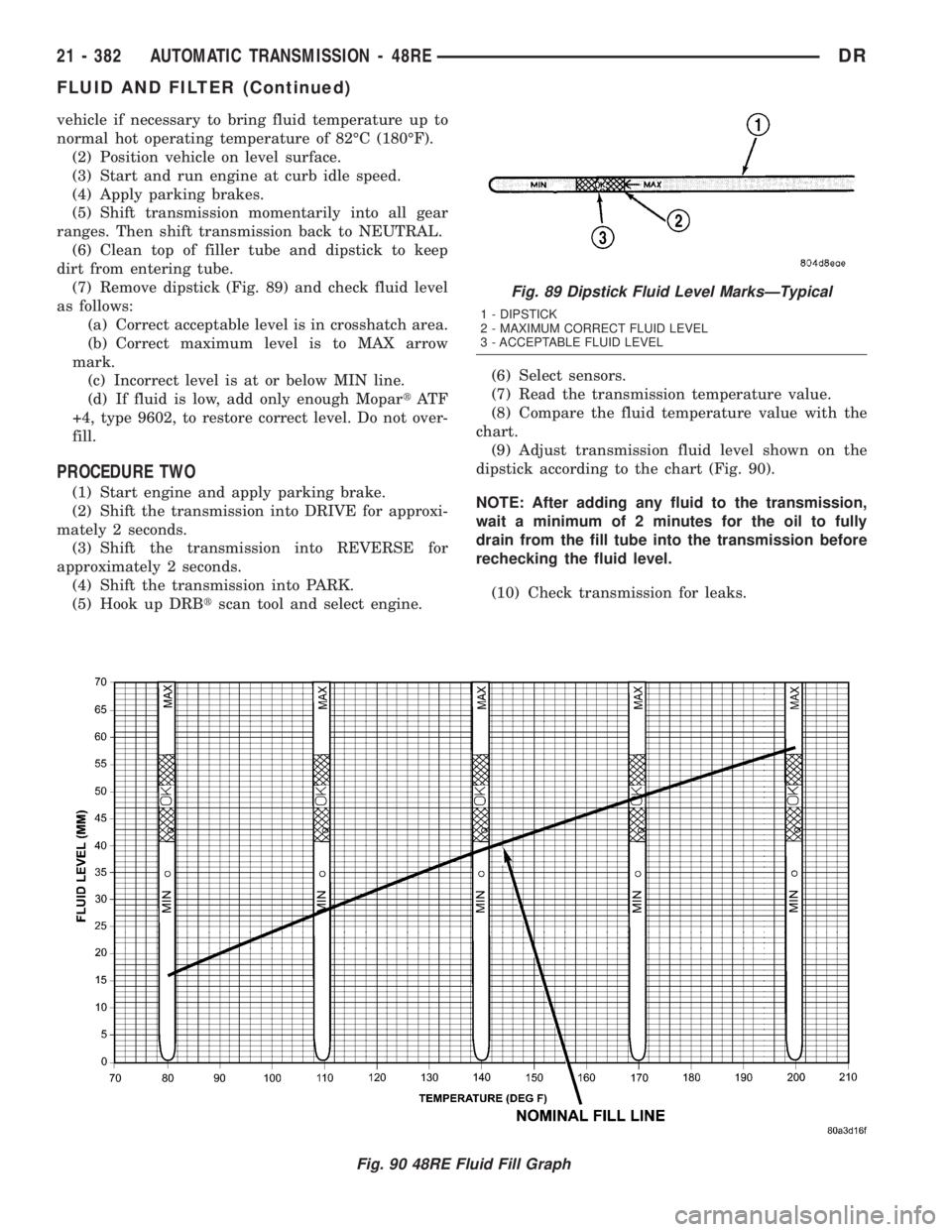
(7) Remove dipstick (Fig. 89) and check fluid level
as follows:
(a) Correct acceptable level is in crosshatch area.
(b) Correct maximum level is to MAX arrow
mark.
(c) Incorrect level is at or below MIN line.
(d) If fluid is low, add only enough MopartAT F
+4, type 9602, to restore correct level. Do not over-
fill.
PROCEDURE TWO
(1) Start engine and apply parking brake.
(2) Shift the transmission into DRIVE for approxi-
mately 2 seconds.
(3) Shift the transmission into REVERSE for
approximately 2 seconds.
(4) Shift the transmission into PARK.
(5) Hook up DRBtscan tool and select engine.(6) Select sensors.
(7) Read the transmission temperature value.
(8) Compare the fluid temperature value with the
chart.
(9) Adjust transmission fluid level shown on the
dipstick according to the chart (Fig. 90).
NOTE: After adding any fluid to the transmission,
wait a minimum of 2 minutes for the oil to fully
drain from the fill tube into the transmission before
rechecking the fluid level.
(10) Check transmission for leaks.
Fig. 90 48RE Fluid Fill Graph
Fig. 89 Dipstick Fluid Level MarksÐTypical
1 - DIPSTICK
2 - MAXIMUM CORRECT FLUID LEVEL
3 - ACCEPTABLE FLUID LEVEL
21 - 382 AUTOMATIC TRANSMISSION - 48REDR
FLUID AND FILTER (Continued)
Page 2381 of 2895
²internal failure that generates debris
²overheat that generates sludge (fluid break-
down)
²failure to replace contaminated converter after
repair
The use of non-recommended fluids can result in
transmission failure. The usual results are erratic
shifts, slippage, abnormal wear and eventual failure
due to fluid breakdown and sludge formation. Avoid
this condition by using recommended fluids only.
The dipstick cap and fill tube should be wiped
clean before checking fluid level. Dirt, grease and
other foreign material on the cap and tube could fall
into the tube if not removed beforehand. Take the
time to wipe the cap and tube clean before withdraw-
ing the dipstick.
Engine coolant in the transmission fluid is gener-
ally caused by a cooler malfunction. The only remedy
is to replace the radiator as the cooler in the radiator
is not a serviceable part. If coolant has circulated
through the transmission, an overhaul is necessary.
The torque converter should be replaced whenever
a failure generates sludge and debris. This is neces-
sary because normal converter flushing procedures
will not remove all contaminants.
STANDARD PROCEDURE
STANDARD PROCEDURE - FLUID LEVEL
CHECK
Low fluid level can cause a variety of conditions
because it allows the pump to take in air along with
the fluid. As in any hydraulic system, air bubbles
make the fluid spongy, therefore, pressures will be
low and build up slowly.
Improper filling can also raise the fluid level too
high. When the transmssion has too much fluid, the
geartrain churns up foam and cause the same condi-
tions which occur with a low fluid level.
In either case, air bubbles can cause overheating
and/or fluid oxidation, and varnishing. This can
interfere with normal valve, clutch, and accumulator
operation. Foaming can also result in fluid escaping
from the transmission vent where it may be mis-
taken for a leak.
After the fluid has been checked, seat the dipstick
fully to seal out water and dirt.
The transmission has a dipstick to check oil level.
It is located on the right side of the engine. Be sure
to wipe all dirt from dipstick handle before removing.
The torque converter fills in both the P (PARK)
and N (NEUTRAL) positions. Place the selector lever
in P (PARK) to be sure that the fluid level check is
accurate.The engine should be running at idle
speed for at least one minute, with the vehicleon level ground.At normal operating temperature
(approximately 82 C. or 180 F.), the fluid level is cor-
rect if it is in the HOT region (cross-hatched area) on
the oil level indicator. The fluid level will be approx-
imately at the upper COLD hole of the dipstick at
70É F fluid temperature.
NOTE: Engine and Transmission should be at nor-
mal operating temperature before performing this
procedure.
(1) Start engine and apply parking brake.
(2) Shift the transmission into DRIVE for approxi-
mately 2 seconds.
(3) Shift the transmission into REVERSE for
approximately 2 seconds.
(4) Shift the transmission into PARK.
(5) Hook up DRBtscan tool and select transmis-
sion.
(6) Select sensors.
(7) Read the transmission temperature value.
(8) Compare the fluid temperature value with the
chart. (Fig. 66)
(9) Adjust transmission fluid level shown on the
dipstick according to the chart.
NOTE: After adding any fluid to the transmission,
wait a minimum of 2 minutes for the oil to fully
drain from the fill tube into the transmission before
rechecking the fluid level.
(10) Check transmission for leaks.
STANDARD PROCEDURE - FLUID AND FILTER
REPLACEMENT
For proper service intervals (Refer to LUBRICA-
TION & MAINTENANCE/MAINTENANCE SCHED-
ULES - DESCRIPTION).
REMOVAL
(1) Hoist and support vehicle on safety stands.
(2) Place a large diameter shallow drain pan
beneath the transmission pan.
(3) Remove bolts holding front and sides of pan to
transmission.
(4) Loosen bolts holding rear of pan to transmis-
sion.
(5) Slowly separate front of pan away from trans-
mission allowing the fluid to drain into drain pan.
(6) Hold up pan and remove remaining bolts hold-
ing pan to transmission.
(7) While holding pan level, lower pan away from
transmission.
(8) Pour remaining fluid in pan into drain pan.
(9) Remove screw holding filter to valve body (Fig.
67).
21 - 542 AUTOMATIC TRANSMISSION - 45RFE/545RFEDR
FLUID AND FILTER (Continued)
Page 2579 of 2895

Adhesion Promoter/Surface Modifier:
Adhesion Promoters/Surface Modifiers are required
for certain plastics. All three categories may have
plastics that require the use of adhesion promoter/
surface modifiers. Always follow repair material man-
ufacturer's plastic identification and repair
procedures.
SAFETY PRECAUTION AND WARNINGS
WARNING:
²EYE PROTECTION SHOULD BE USED WHEN
SERVICING COMPONENTS. PERSONAL INJURY
CAN RESULT.
²USE AN OSHA APPROVED BREATHING MASK
WHEN MIXING EPOXY, GRINDING, AND SPRAYING
PAINT OR SOLVENTS IN A CONFINED AREA. PER-
SONAL INJURY CAN RESULT.²AVOID PROLONGED SKIN CONTACT WITH
RESIN, PETROLEUM, OR ALCOHOL BASED SOL-
VENTS. PERSONAL INJURY CAN RESULT.
²DO NOT VENTURE UNDER A HOISTED VEHI-
CLE THAT IS NOT PROPERLY SUPPORTED ON
SAFETY STANDS. PERSONAL INJURY CAN
RESULT.
NOTE:
²When holes must be drilled or cut in body pan-
els, verify locations of internal body components
and electrical wiring. Damage to vehicle can result.
²Do not use abrasive chemicals or compounds
on undamaged painted surfaces around repair
areas. Damage to finish can result.
RIGID, SEMI-RIGID, AND FLEXIBLE PLASTIC PARTS TYPES
CODE FAMILY NAME COMMON TRADE NAME TYPICAL APPLICATION
ASA ACRYLONITRILE STYRENE
ACRYLITELURAN S CONSOLES, GRILLES
ABS ACRYLONITRILE
BUTADIENE STYRENETERLURAN9A9PILLARS, CONSOLES,
GRILLES
ABS/PC ABS/PC ALLOY PULSE, PROLOY,
BAYBLENDDOORS, INSTRUMENT
PANELS
ABS/PVC ABS/PV ALLOY PROLOY, PULSE, LUSTRAN,
CYCLOVINDOOR PANELS, GRILLES,
TRIM
BMC BULK MOLDING
COMPOUNDBMC FENDER EXTENSIONS
EMA EHTYLENE METHYL
ACRYLATE/IONOMERSURLYN, EMA, IONOMER BUMPER GUARDS, PADS
METTON METTON METTON GRILLES, KICK PANELS,
RUNNING BOARDS
MPPO MODIFIED
POLYPHENYLENE OXIDEMPPO SPOILER ASSEMBLY
PA POLYAMID ZYTEL, VYDYNE, PA,
MINLONFENDERS, QUARTER PANELS
PET THERMOPLASTIC
POLYESTERRYNITE TRIM
PBT/PPO PBT/PPO ALLOY GERMAX CLADDINGS
PBTP POLYBUTYLENE
THEREPTHALATEPBT, PBTP, POCAN, VALOX WHEEL COVERS, FENDERS,
GRILLES
PBTP/EEBC POLYBUTYLENE
THEREPTHALATE/EEBC
ALLOYBEXLOY,9M9, PBTP/EEBC FASCIAS, ROCKER PANEL,
MOLDINGS
PC POLYCARBONATE LEXAN, MERLON, CALIBRE,
MAKROLON PCTAIL LIGHT LENSES, IP TRIM,
VALANCE PANELS
23 - 4 BODYDR
BODY (Continued)
Page 2856 of 2895
ABS - DESCRIPTION, BRAKES...........5-39
ABS - OPERATION, BRAKES.............5-39
ABS BRAKE BLEEDING - STANDARD
PROCEDURE.........................5-40
ABS INDICATOR - DESCRIPTION.........8J-17
ABS INDICATOR - OPERATION..........8J-17
A/C APPLICATION TABLE,
SPECIFICATIONS......................24-7
A/C COMPRESSOR CLUTCH -
DESCRIPTION........................24-9
A/C COMPRESSOR CLUTCH -
INSPECTION........................24-12
A/C COMPRESSOR CLUTCH -
INSTALLATION.......................24-12
A/C COMPRESSOR CLUTCH -
OPERATION..........................24-9
A/C COMPRESSOR CLUTCH - REMOVAL . . 24-10
A/C COMPRESSOR CLUTCH BREAK-IN -
STANDARD PROCEDURE...............24-10
A/C COMPRESSOR CLUTCH COIL -
DIAGNOSIS AND TESTING.............24-10
A/C COMPRESSOR CLUTCH RELAY -
DESCRIPTION.......................24-13
A/C COMPRESSOR CLUTCH RELAY -
INSTALLATION.......................24-14
A/C COMPRESSOR CLUTCH RELAY -
OPERATION.........................24-13
A/C COMPRESSOR CLUTCH RELAY -
REMOVAL..........................24-14
A/C COMPRESSOR NOISE - DIAGNOSIS
AND TESTING.......................24-36
A/C CONDENSER - DESCRIPTION.........24-39
A/C CONDENSER - OPERATION..........24-39
A/C EVAPORATOR - DESCRIPTION.......24-47
A/C EVAPORATOR - INSTALLATION......24-47
A/C EVAPORATOR - OPERATION.........24-47
A/C EVAPORATOR - REMOVAL..........24-47
A/C HEATER CONTROL - DESCRIPTION . . . 24-14
A/C HEATER CONTROL - INSTALLATION . . . 24-15
A/C HEATER CONTROL - REMOVAL......24-14
A/C ORIFICE TUBE - DESCRIPTION.......24-48
A/C ORIFICE TUBE - INSTALLATION......24-49
A/C ORIFICE TUBE - OPERATION........24-48
A/C ORIFICE TUBE - REMOVAL..........24-49
A/C PERFORMANCE - DIAGNOSIS AND
TESTING............................24-2
A/C PRESSURE TRANSDUCER -
DESCRIPTION.......................24-15
A/C PRESSURE TRANSDUCER -
DIAGNOSIS AND TESTING.............24-15
A/C PRESSURE TRANSDUCER -
INSTALLATION.......................24-16
A/C PRESSURE TRANSDUCER -
OPERATION.........................24-15
A/C PRESSURE TRANSDUCER -
REMOVAL..........................24-16
ACCELERATOR PEDAL - INSTALLATION . . . 14-24
ACCELERATOR PEDAL - REMOVAL.......14-24
ACCELERATOR PEDAL POSITION
SENSOR - DESCRIPTION...............14-25
ACCELERATOR PEDAL POSITION
SENSOR - INSTALLATION..............14-25
ACCELERATOR PEDAL POSITION
SENSOR - OPERATION................14-25
ACCELERATOR PEDAL POSITION
SENSOR - REMOVAL..................14-25
ACCESSORY DRIVE BELT - DIAGNOSIS
AND TESTING................7-25,7-28,7-31
ACCUMULATOR - DESCRIPTION.........24-49
ACCUMULATOR - DESCRIPTION
. . 21-191,21-372
ACCUMULATOR - INSPECTION
. . . 21-192,21-373
ACCUMULATOR - INSTALLATION
........24-50
ACCUMULATOR - OPERATION
..........24-49
ACCUMULATOR - OPERATION
....21-192,21-373
ACCUMULATOR - REMOVAL
............24-49
ACM COVER - INSTALLATION
............8O-9
ACM COVER - REMOVAL
...............8O-9
ACTUATION TEST MODE - DESCRIPTION,
CIRCUIT
.............................25-1
ACTUATOR - DESCRIPTION, BLEND
DOOR
.............................24-16
ACTUATOR - DESCRIPTION, FUEL
CONTROL
..........................14-85
ACTUATOR - DESCRIPTION, MODE
DOOR
.............................24-20
ACTUATOR - DESCRIPTION,
RECIRCULATION DOOR
................24-22ACTUATOR - INSTALLATION, BLEND
DOOR.............................24-17
ACTUATOR - INSTALLATION, FLOOR -
DEFROST DOOR.....................24-20
ACTUATOR - INSTALLATION, FUEL
CONTROL..........................14-85
ACTUATOR - INSTALLATION, INSIDE
HANDLE.......................23-22,23-32
ACTUATOR - INSTALLATION, MODE
DOOR.............................24-22
ACTUATOR - INSTALLATION,
RECIRCULATION DOOR................24-23
ACTUATOR - OPERATION, BLEND DOOR . . 24-16
ACTUATOR - OPERATION, FUEL
CONTROL..........................14-85
ACTUATOR - OPERATION, MODE DOOR . . . 24-21
ACTUATOR - OPERATION,
RECIRCULATION DOOR................24-22
ACTUATOR - REMOVAL, BLEND DOOR....24-17
ACTUATOR - REMOVAL, FLOOR -
DEFROST DOOR.....................24-19
ACTUATOR - REMOVAL, FUEL CONTROL . . 14-85
ACTUATOR - REMOVAL, INSIDE HANDLE . 23-22,
23-31
ACTUATOR - REMOVAL, MODE DOOR....24-21
ACTUATOR - REMOVAL, RECIRCULATION
DOOR.............................24-22
ADAPTER HOUSING SEAL -
INSTALLATION...........21-127,21-539,21-83
ADAPTER HOUSING SEAL - REMOVAL . . 21-127,
21-539,21-83
ADAPTER MOUNT - INSTALLATION, DISC
BRAKE CALIPER......................5-17
ADDING ADDITIONAL COOLANT -
STANDARD PROCEDURE................7-19
ADDITIONAL COOLANT - STANDARD
PROCEDURE, ADDING..................7-19
ADHESIVE LOCATIONS -
SPECIFICATIONS, STRUCTURAL........23-113
ADJUSTABLE PEDAL MOTOR -
DESCRIPTION........................5-24
ADJUSTABLE PEDAL MOTOR -
INSTALLATION........................5-24
ADJUSTABLE PEDAL MOTOR - REMOVAL . . 5-24
ADJUSTABLE PEDAL SWITCH -
INSTALLATION.........................5-6
ADJUSTABLE PEDAL SWITCH -
REMOVAL............................5-6
ADJUSTER - DIAGNOSIS AND TESTING,
HYDRAULIC LASH................9-124,9-31
ADJUSTER - INSTALLATION, SEAT BELT
TURNING LOOP.....................8O-50
ADJUSTER - REMOVAL, SEAT BELT
TURNING LOOP.....................8O-50
ADJUSTER ASSEMBLY - DESCRIPTION,
ROCKER ARM.......................9-124
ADJUSTER ASSEMBLY - INSTALLATION,
ROCKER ARM..................9-124,9-249
ADJUSTER ASSEMBLY - REMOVAL,
ROCKER ARM..................9-124,9-249
ADJUSTER ASSY - CLEANING, ROCKER
ARM
..............................9-310
ADJUSTER ASSY - DESCRIPTION,
ROCKER ARM
.......................9-310
ADJUSTER ASSY - INSPECTION,
ROCKER ARM
.......................9-311
ADJUSTER ASSY - INSTALLATION,
ROCKER ARM
.............9-198,9-312,9-379
ADJUSTER ASSY - REMOVAL, ROCKER
ARM
....................9-198,9-310,9-379
ADJUSTING TOOL - ADJUSTMENT, WITH
. . . 5-36
AFTER A SUPPLEMENTAL RESTRAINT
DEPLOYMENT - STANDARD
PROCEDURE, SERVICE
.................8O-7
AIR CHECKING TRANSMISSION CLUTCH
OPERATION - DIAGNOSIS AND
TESTING
..........................21-494
AIR CLEANER ELEMENT - INSTALLATION
. 9-105,
9-20,9-242,9-298,9-370
AIR CLEANER ELEMENT - REMOVAL
. 9-105,9-20,
9-242,9-297,9-370
AIR CONDITIONER - DESCRIPTION,
HEATER
.............................24-1
AIR CONDITIONER - OPERATION,
HEATER
.............................24-1
AIR CONDITIONING - INSTALLATION,
WATER PUMP BYPASS HOSE WITH
.......7-70AIR CONDITIONING - INSTALLATION,
WATER PUMP BYPASS HOSE
WITHOUT............................7-70
AIR CONDITIONING - REMOVAL, WATER
PUMP BYPASS HOSE WITH.............7-68
AIR CONDITIONING - REMOVAL, WATER
PUMP BYPASS HOSE WITHOUT..........7-69
AIR CONTROL MOTOR - DESCRIPTION,
IDLE...............................14-33
AIR CONTROL MOTOR - INSTALLATION,
IDLE...............................14-35
AIR CONTROL MOTOR - OPERATION,
IDLE...............................14-33
AIR CONTROL MOTOR - REMOVAL, IDLE . . 14-34
AIR COOLER AND PLUMBING -
CLEANING, CHARGE..................11-16
AIR COOLER AND PLUMBING -
DESCRIPTION, CHARGE...............11-15
AIR COOLER AND PLUMBING -
INSPECTION, CHARGE.................11-16
AIR COOLER AND PLUMBING -
INSTALLATION, CHARGE...............11-16
AIR COOLER AND PLUMBING -
OPERATION, CHARGE.................11-15
AIR COOLER AND PLUMBING -
REMOVAL, CHARGE..................11-15
AIR COOLER SYSTEM - LEAKS -
DIAGNOSIS AND TESTING, CHARGE......11-15
AIR DAM - INSTALLATION, FRONT........13-2
AIR DAM - REMOVAL, FRONT...........13-2
AIR HEATER - DESCRIPTION, INTAKE.....14-91
AIR HEATER - INSTALLATION, INTAKE....14-91
AIR HEATER - OPERATION, INTAKE......14-91
AIR HEATER - REMOVAL, INTAKE........14-91
AIR HEATER RELAY - DESCRIPTION,
INTAKE ............................14-92
AIR HEATER RELAY - INSTALLATION,
INTAKE ............................14-93
AIR HEATER RELAY - OPERATION,
INTAKE ............................14-92
AIR HEATER RELAY - REMOVAL, INTAKE . . 14-93
AIR INTAKE SYSTEM - INSTALLATION....9-194
AIR INTAKE SYSTEM - REMOVAL........9-194
AIR TEMPERATURE SENSOR -
DESCRIPTION, INTAKE................14-36
AIR TEMPERATURE SENSOR -
INSTALLATION, INTAKE................14-38
AIR TEMPERATURE SENSOR -
OPERATION, INTAKE..................14-36
AIR TEMPERATURE SENSOR -
REMOVAL, INTAKE...................14-36
AIR TEMPERATURE SENSOR/MAP
SENSOR - DESCRIPTION, INTAKE........14-93
AIR TEMPERATURE SENSOR/MAP
SENSOR - INSTALLATION, INTAKE.......14-94
AIR TEMPERATURE SENSOR/MAP
SENSOR - OPERATION, INTAKE.........14-93
AIR TEMPERATURE SENSOR/MAP
SENSOR - REMOVAL, INTAKE...........14-93
AIR TEMPERATURE SENSOR/PRESSURE
SENSOR - DESCRIPTION, INLET.........14-90
AIR TEMPERATURE SENSOR/PRESSURE
SENSOR - INSTALLATION, INLET........14-90
AIR TEMPERATURE SENSOR/PRESSURE
SENSOR - OPERATION, INLET..........14-90
AIR TEMPERATURE SENSOR/PRESSURE
SENSOR - REMOVAL, INLET............14-90
AIR TESTING TRANSMISSION CLUTCH
AND BAND OPERATION - DIAGNOSIS
AND TESTING................21-143,21-324
AIR TO OIL COOLER - INSTALLATION.....7-75
AIR TO OIL COOLER - REMOVAL.........7-74
AIRBAG - DESCRIPTION, DRIVER........8O-22
AIRBAG - DESCRIPTION, PASSENGER....8O-34
AIRBAG - DESCRIPTION, SIDE CURTAIN . . 8O-51
AIRBAG - INSTALLATION, DRIVER.......8O-24
AIRBAG - INSTALLATION, PASSENGER . . . 8O-37
AIRBAG - INSTALLATION, SIDE CURTAIN . . 8O-53
AIRBAG - OPERATION, DRIVER.........8O-23
AIRBAG - OPERATION, PASSENGER......8O-35
AIRBAG - OPERATION, SIDE CURTAIN....8O-51
AIRBAG - REMOVAL, DRIVER
...........8O-23
AIRBAG - REMOVAL, PASSENGER
.......8O-35
AIRBAG - REMOVAL, SIDE CURTAIN
.....8O-52
AIRBAG CONTROL MODULE -
DESCRIPTION
.......................8O-10
AIRBAG CONTROL MODULE -
DESCRIPTION, SIDE IMPACT
...........8O-53
DRINDEX 1
Description Group-Page Description Group-Page Description Group-Page