2003 DODGE RAM Blend door actuator
[x] Cancel search: Blend door actuatorPage 1147 of 2895
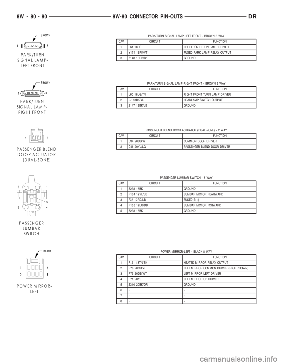
PARK/TURN SIGNAL LAMP-LEFT FRONT - BROWN 3 WAY
CAV CIRCUIT FUNCTION
1 L61 18LG LEFT FRONT TURN LAMP DRIVER
2 Y174 18PK/VT FUSED PARK LAMP RELAY OUTPUT
3 Z148 18DB/BK GROUND
PARK/TURN SIGNAL LAMP-RIGHT FRONT - BROWN 3 WAY
CAV CIRCUIT FUNCTION
1 L60 18LG/TN RIGHT FRONT TURN LAMP DRIVER
2 L7 18BK/YL HEADLAMP SWITCH OUTPUT
3 Z147 18BK/LB GROUND
PASSENGER BLEND DOOR ACTUATOR (DUAL-ZONE)-2WAY
CAV CIRCUIT FUNCTION
1 C34 20DB/WT COMMON DOOR DRIVER
2 C46 20YL/LG PASSENGER BLEND DOOR DRIVER
PASSENGER LUMBAR SWITCH-5WAY
CAV CIRCUIT FUNCTION
1 Z238 18BK GROUND
2 P104 12YL/LB LUMBAR MOTOR REARWARD
3 F37 12RD/LB FUSED B(+)
4 P105 12LG/DB LUMBAR MOTOR FORWARD
5 Z238 18BK GROUND
POWER MIRROR-LEFT - BLACK 8 WAY
CAV CIRCUIT FUNCTION
1 F121 18TN/BK HEATED MIRROR RELAY OUTPUT
2 P76 20OR/YL LEFT MIRROR COMMON DRIVER (RIGHT/DOWN)
3 P75 20DB/WT LEFT MIRROR LEFT DRIVER
4 P71 20YL LEFT MIRROR UP DRIVER
5 Z310 20BK/OR GROUND
6- -
7- -
8- -
8W - 80 - 80 8W-80 CONNECTOR PIN-OUTSDR
Page 1178 of 2895
8W-91 CONNECTOR/GROUND/SPLICE LOCATION
TABLE OF CONTENTS
page
CONNECTOR/GROUND/SPLICE LOCATION
DESCRIPTION..........................1
CONNECTOR/GROUND/SPLICE
LOCATION
DESCRIPTION
This section provides illustrations identifying con-
nector, ground, and splice locations in the vehicle.
Connector, ground, and splice indexes are provided.Use the wiring diagrams in each section for connec-
tor, ground, and splice identification. Refer to the
index for the proper figure number. For items that
are not shown in this section N/S is placed in the
Fig. column.
CONNECTORS
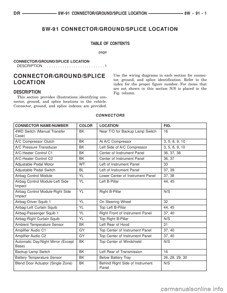
CONNECTOR NAME/NUMBER COLOR LOCATION FIG.
4WD Switch (Manual Transfer
Case)BK Near T/O for Backup Lamp Switch 16
A/C Compressor Clutch BK At A/C Compressor 3, 5, 8, 9, 10
A/C Pressure Transducer BK Left Side of A/C Compressor 3, 5, 8, 9, 10
A/C-Heater Control C1 BK Center of Instrument Panel 36, 37, 38
A/C-Heater Control C2 BK Center of Instrument Panel 36, 37
Adjustable Pedal Motor WT Left of Instrument Panel 33
Adjustable Pedal Switch BL Left of Instrument Panel 37, 39
Airbag Control Module YL Lower Center of Instrument Panel 37, 38
Airbag Control Module-Left Side
ImpactYL Left B-Pillar 44, 45
Airbag Control Module-Right Side
ImpactYL Right B-Pillar N/S
Airbag-Driver Squib 1 YL On Steering Wheel 32
Airbag-Left Curtain Squib YL Top Left B-Pillar 44, 45
Airbag-Passenger Squib 1 YL Right Front of Instrument Panel 37, 40
Airbag-Right Curtain Squib YL Top Right B-Pillar N/S
Ambient Temperature Sensor BK Left Rear of Hood 31
Amplifier Audio C1 GY Top Center of Instrument Panel 37, 40
Amplifier Audio C2 GY Top Center of Instrument Panel 37, 40
Automatic Day/Night Mirror (Except
Base)BK Top Center of Windshield N/S
Backup Lamp Switch BK Left Rear of Transmission 16
Battery Temperature Sensor BK Below Battery Tray 26, 28, 29, 30
Blend Door Actuator (Single Zone) BK Behind Right Side of Instrument
PanelN/S
DR8W-91 CONNECTOR/GROUND/SPLICE LOCATION 8W - 91 - 1
Page 1181 of 2895
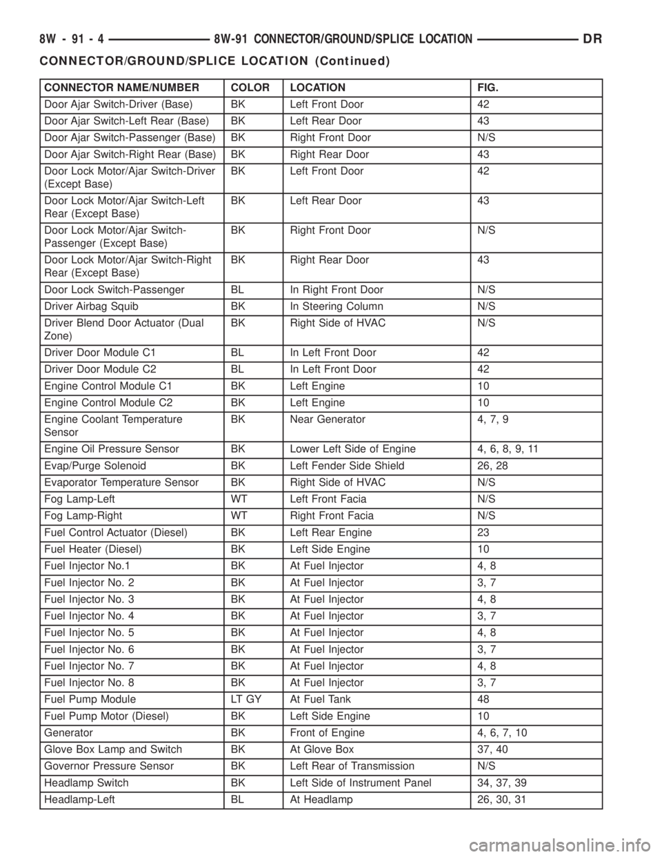
CONNECTOR NAME/NUMBER COLOR LOCATION FIG.
Door Ajar Switch-Driver (Base) BK Left Front Door 42
Door Ajar Switch-Left Rear (Base) BK Left Rear Door 43
Door Ajar Switch-Passenger (Base) BK Right Front Door N/S
Door Ajar Switch-Right Rear (Base) BK Right Rear Door 43
Door Lock Motor/Ajar Switch-Driver
(Except Base)BK Left Front Door 42
Door Lock Motor/Ajar Switch-Left
Rear (Except Base)BK Left Rear Door 43
Door Lock Motor/Ajar Switch-
Passenger (Except Base)BK Right Front Door N/S
Door Lock Motor/Ajar Switch-Right
Rear (Except Base)BK Right Rear Door 43
Door Lock Switch-Passenger BL In Right Front Door N/S
Driver Airbag Squib BK In Steering Column N/S
Driver Blend Door Actuator (Dual
Zone)BK Right Side of HVAC N/S
Driver Door Module C1 BL In Left Front Door 42
Driver Door Module C2 BL In Left Front Door 42
Engine Control Module C1 BK Left Engine 10
Engine Control Module C2 BK Left Engine 10
Engine Coolant Temperature
SensorBK Near Generator 4, 7, 9
Engine Oil Pressure Sensor BK Lower Left Side of Engine 4, 6, 8, 9, 11
Evap/Purge Solenoid BK Left Fender Side Shield 26, 28
Evaporator Temperature Sensor BK Right Side of HVAC N/S
Fog Lamp-Left WT Left Front Facia N/S
Fog Lamp-Right WT Right Front Facia N/S
Fuel Control Actuator (Diesel) BK Left Rear Engine 23
Fuel Heater (Diesel) BK Left Side Engine 10
Fuel Injector No.1 BK At Fuel Injector 4, 8
Fuel Injector No. 2 BK At Fuel Injector 3, 7
Fuel Injector No. 3 BK At Fuel Injector 4, 8
Fuel Injector No. 4 BK At Fuel Injector 3, 7
Fuel Injector No. 5 BK At Fuel Injector 4, 8
Fuel Injector No. 6 BK At Fuel Injector 3, 7
Fuel Injector No. 7 BK At Fuel Injector 4, 8
Fuel Injector No. 8 BK At Fuel Injector 3, 7
Fuel Pump Module LT GY At Fuel Tank 48
Fuel Pump Motor (Diesel) BK Left Side Engine 10
Generator BK Front of Engine 4, 6, 7, 10
Glove Box Lamp and Switch BK At Glove Box 37, 40
Governor Pressure Sensor BK Left Rear of Transmission N/S
Headlamp Switch BK Left Side of Instrument Panel 34, 37, 39
Headlamp-Left BL At Headlamp 26, 30, 31
8W - 91 - 4 8W-91 CONNECTOR/GROUND/SPLICE LOCATIONDR
CONNECTOR/GROUND/SPLICE LOCATION (Continued)
Page 1183 of 2895
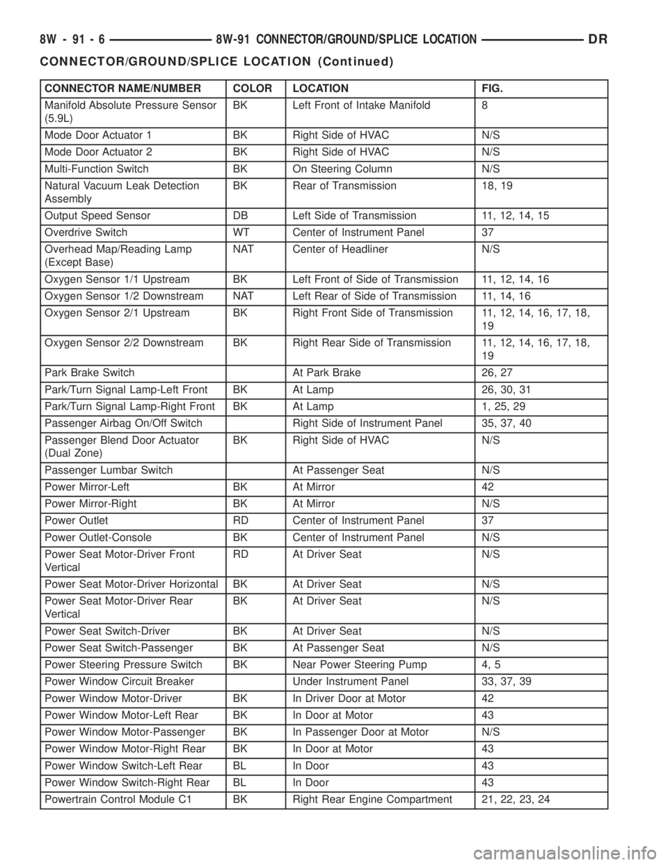
CONNECTOR NAME/NUMBER COLOR LOCATION FIG.
Manifold Absolute Pressure Sensor
(5.9L)BK Left Front of Intake Manifold 8
Mode Door Actuator 1 BK Right Side of HVAC N/S
Mode Door Actuator 2 BK Right Side of HVAC N/S
Multi-Function Switch BK On Steering Column N/S
Natural Vacuum Leak Detection
AssemblyBK Rear of Transmission 18, 19
Output Speed Sensor DB Left Side of Transmission 11, 12, 14, 15
Overdrive Switch WT Center of Instrument Panel 37
Overhead Map/Reading Lamp
(Except Base)NAT Center of Headliner N/S
Oxygen Sensor 1/1 Upstream BK Left Front of Side of Transmission 11, 12, 14, 16
Oxygen Sensor 1/2 Downstream NAT Left Rear of Side of Transmission 11, 14, 16
Oxygen Sensor 2/1 Upstream BK Right Front Side of Transmission 11, 12, 14, 16, 17, 18,
19
Oxygen Sensor 2/2 Downstream BK Right Rear Side of Transmission 11, 12, 14, 16, 17, 18,
19
Park Brake Switch At Park Brake 26, 27
Park/Turn Signal Lamp-Left Front BK At Lamp 26, 30, 31
Park/Turn Signal Lamp-Right Front BK At Lamp 1, 25, 29
Passenger Airbag On/Off Switch Right Side of Instrument Panel 35, 37, 40
Passenger Blend Door Actuator
(Dual Zone)BK Right Side of HVAC N/S
Passenger Lumbar Switch At Passenger Seat N/S
Power Mirror-Left BK At Mirror 42
Power Mirror-Right BK At Mirror N/S
Power Outlet RD Center of Instrument Panel 37
Power Outlet-Console BK Center of Instrument Panel N/S
Power Seat Motor-Driver Front
VerticalRD At Driver Seat N/S
Power Seat Motor-Driver Horizontal BK At Driver Seat N/S
Power Seat Motor-Driver Rear
VerticalBK At Driver Seat N/S
Power Seat Switch-Driver BK At Driver Seat N/S
Power Seat Switch-Passenger BK At Passenger Seat N/S
Power Steering Pressure Switch BK Near Power Steering Pump 4, 5
Power Window Circuit Breaker Under Instrument Panel 33, 37, 39
Power Window Motor-Driver BK In Driver Door at Motor 42
Power Window Motor-Left Rear BK In Door at Motor 43
Power Window Motor-Passenger BK In Passenger Door at Motor N/S
Power Window Motor-Right Rear BK In Door at Motor 43
Power Window Switch-Left Rear BL In Door 43
Power Window Switch-Right Rear BL In Door 43
Powertrain Control Module C1 BK Right Rear Engine Compartment 21, 22, 23, 24
8W - 91 - 6 8W-91 CONNECTOR/GROUND/SPLICE LOCATIONDR
CONNECTOR/GROUND/SPLICE LOCATION (Continued)
Page 2776 of 2895
HEATING & AIR CONDITIONING
TABLE OF CONTENTS
page page
HEATING & AIR CONDITIONING
DESCRIPTION
DESCRIPTION - HEATER AND AIR
CONDITIONER........................1
DESCRIPTION - COOLING SYSTEM
REQUIREMENTS.......................1
DESCRIPTION - REFRIGERANT SYSTEM
SERVICE PORT........................1
OPERATION
OPERATION - HEATER AND AIR
CONDITIONER........................1
OPERATION - REFRIGERANT SYSTEM
SERVICE PORT........................2DIAGNOSIS AND TESTING
DIAGNOSIS AND TESTING - A/C
PERFORMANCE.......................2
DIAGNOSIS AND TESTING - HEATER
PERFORMANCE.......................5
STANDARD PROCEDURE - DIODE
REPLACEMENT.......................7
SPECIFICATIONS
A/C APPLICATION TABLE................7
SPECIFICATIONS......................8
CONTROLS.............................9
DISTRIBUTION..........................24
PLUMBING.............................31
HEATING & AIR
CONDITIONING
DESCRIPTION
DESCRIPTION - HEATER AND AIR
CONDITIONER
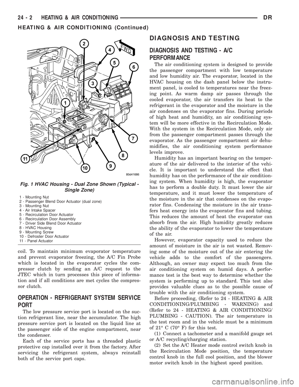
All vehicles are equipped with a common HVAC
housing assembly (Fig. 1). The system combines air
conditioning, heating, and ventilating capabilities in
a single unit housing mounted under the instrument
panel.
DESCRIPTION - COOLING SYSTEM
REQUIREMENTS
To maintain the performance level of the HVAC
system, the engine cooling system must be properly
maintained. The use of a bug screen is not recom-
mended. Any obstructions in front of the radiator or
condenser will reduce the performance of the air con-
ditioning and engine cooling systems.
The engine cooling system includes the heater core
and the heater hoses. Refer to Engine Cooling for
more information before the opening of, or attempt-
ing any service to the engine cooling system.
DESCRIPTION - REFRIGERANT SYSTEM
SERVICE PORT
The two refrigerant system service ports are used
to charge, recover/recycle, evacuate, and test the air
conditioning refrigerant system. Unique service port
coupler sizes are used on the R-134a system, toensure that the refrigerant system is not accidentally
contaminated by the use of the wrong refrigerant
(R-12), or refrigerant system service equipment.
OPERATION
OPERATION - HEATER AND AIR CONDITIONER
The heater air conditioner are blend-air type sys-
tems. In a blend-air system, a blend door controls the
amount of unconditioned air (or cooled air from the
evaporator on models with air conditioning) that is
allowed to flow through, or around, the heater core. A
temperature control knob on the A/C Heater control
panel determines the discharge air temperature by
controlling an electric actuator, which moves the
blend door. This allows an almost immediate control
of the output air temperature of the system.
The mode control knob on the A/C Heater control
panel is used to direct the conditioned air to the
selected system outlets. Both mode control switches
use electric actuators to control the mode doors.
On all vehicles, the outside air intake can be shut
off by selecting the Recirculation Mode with the
mode control knob. This will operate a electric actu-
ated recirculation door that closes off the outside
fresh air intake and recirculates the air that is
already inside the vehicle.
The air conditioner for all models is designed for
the use of non-CFC, R-134a refrigerant. The air con-
ditioning system has an evaporator to cool and dehu-
midify the incoming air prior to blending it with the
heated air. This air conditioning system uses a fixed
orifice tube in the liquid line near the condenser out-
let tube to meter refrigerant flow to the evaporator
DRHEATING & AIR CONDITIONING 24 - 1
Page 2777 of 2895
coil. To maintain minimum evaporator temperature
and prevent evaporator freezing, the A/C Fin Probe
which is located in the evaporator cycles the com-
pressor clutch by sending an A/C request to the
JTEC which in turn processes this piece of informa-
tion and if all conditions are met cycles the compres-
sor clutch.
OPERATION - REFRIGERANT SYSTEM SERVICE
PORT
The low pressure service port is located on the suc-
tion refrigerant line, near the accumulator. The high
pressure service port is located on the liquid line at
the passenger side of the engine compartment, near
the condenser.
Each of the service ports has a threaded plastic
protective cap installed over it from the factory. After
servicing the refrigerant system, always reinstall
both of the service port caps.
DIAGNOSIS AND TESTING
DIAGNOSIS AND TESTING - A/C
PERFORMANCE
The air conditioning system is designed to provide
the passenger compartment with low temperature
and low humidity air. The evaporator, located in the
HVAC housing on the dash panel below the instru-
ment panel, is cooled to temperatures near the freez-
ing point. As warm damp air passes through the
cooled evaporator, the air transfers its heat to the
refrigerant in the evaporator and the moisture in the
air condenses on the evaporator fins. During periods
of high heat and humidity, an air conditioning sys-
tem will be more effective in the Recirculation Mode.
With the system in the Recirculation Mode, only air
from the passenger compartment passes through the
evaporator. As the passenger compartment air dehu-
midifies, the air conditioning system performance
levels improve.
Humidity has an important bearing on the temper-
ature of the air delivered to the interior of the vehi-
cle. It is important to understand the effect that
humidity has on the performance of the air condition-
ing system. When humidity is high, the evaporator
has to perform a double duty. It must lower the air
temperature, and it must lower the temperature of
the moisture in the air that condenses on the evapo-
rator fins. Condensing the moisture in the air trans-
fers heat energy into the evaporator fins and tubing.
This reduces the amount of heat the evaporator can
absorb from the air. High humidity greatly reduces
the ability of the evaporator to lower the temperature
of the air.
However, evaporator capacity used to reduce the
amount of moisture in the air is not wasted. Remov-
ing some of the moisture out of the air entering the
vehicle adds to the comfort of the passengers.
Although, an owner may expect too much from the
air conditioning system on humid days. A perfor-
mance test is the best way to determine whether the
system is performing up to standard. This test also
provides valuable clues as to the possible cause of
trouble with the air conditioning system.
Before proceeding, (Refer to 24 - HEATING & AIR
CONDITIONING/PLUMBING - WARNING) and
(Refer to 24 - HEATING & AIR CONDITIONING/
PLUMBING - CAUTION). The air temperature in
the test room and in the vehicle must be a minimum
of 21É C (70É F) for this test.
(1) Connect a tachometer and a manifold gauge set
or A/C recycling/charging station.
(2) Set the A/C Heater mode control switch knob in
the Recirculation Mode position, the temperature
control knob in the full cool position, and the blower
motor switch knob in the highest speed position.
Fig. 1 HVAC Housing - Dual Zone Shown (Typical -
Single Zone)
1 - Mounting Nut
2 - Passenger Blend Door Actuator (dual zone)
3 - Mounting Nut
4 - Air Intake Spacer
5 - Recirculation Door Actuator
6 - Recirculation Door Assembly
7 - Driver Side Blend Door Actuator
8 - HVAC Housing
9 - Mounting Screw
10 - Defroster Door Actuator
11 - Panel Actuator
24 - 2 HEATING & AIR CONDITIONINGDR
HEATING & AIR CONDITIONING (Continued)
Page 2779 of 2895
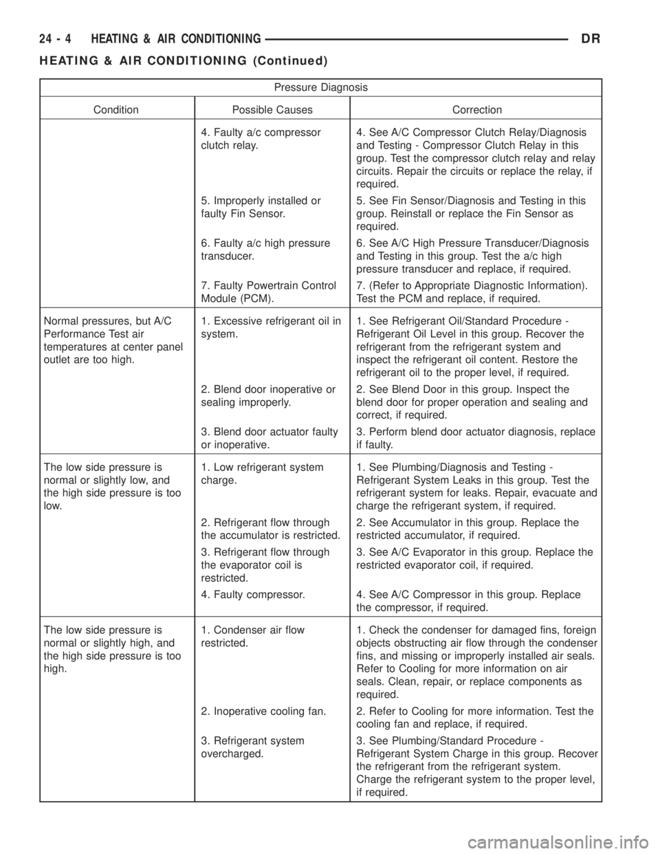
Pressure Diagnosis
Condition Possible Causes Correction
4. Faulty a/c compressor
clutch relay.4. See A/C Compressor Clutch Relay/Diagnosis
and Testing - Compressor Clutch Relay in this
group. Test the compressor clutch relay and relay
circuits. Repair the circuits or replace the relay, if
required.
5. Improperly installed or
faulty Fin Sensor.5. See Fin Sensor/Diagnosis and Testing in this
group. Reinstall or replace the Fin Sensor as
required.
6. Faulty a/c high pressure
transducer.6. See A/C High Pressure Transducer/Diagnosis
and Testing in this group. Test the a/c high
pressure transducer and replace, if required.
7. Faulty Powertrain Control
Module (PCM).7. (Refer to Appropriate Diagnostic Information).
Test the PCM and replace, if required.
Normal pressures, but A/C
Performance Test air
temperatures at center panel
outlet are too high.1. Excessive refrigerant oil in
system.1. See Refrigerant Oil/Standard Procedure -
Refrigerant Oil Level in this group. Recover the
refrigerant from the refrigerant system and
inspect the refrigerant oil content. Restore the
refrigerant oil to the proper level, if required.
2. Blend door inoperative or
sealing improperly.2. See Blend Door in this group. Inspect the
blend door for proper operation and sealing and
correct, if required.
3. Blend door actuator faulty
or inoperative.3. Perform blend door actuator diagnosis, replace
if faulty.
The low side pressure is
normal or slightly low, and
the high side pressure is too
low.1. Low refrigerant system
charge.1. See Plumbing/Diagnosis and Testing -
Refrigerant System Leaks in this group. Test the
refrigerant system for leaks. Repair, evacuate and
charge the refrigerant system, if required.
2. Refrigerant flow through
the accumulator is restricted.2. See Accumulator in this group. Replace the
restricted accumulator, if required.
3. Refrigerant flow through
the evaporator coil is
restricted.3. See A/C Evaporator in this group. Replace the
restricted evaporator coil, if required.
4. Faulty compressor. 4. See A/C Compressor in this group. Replace
the compressor, if required.
The low side pressure is
normal or slightly high, and
the high side pressure is too
high.1. Condenser air flow
restricted.1. Check the condenser for damaged fins, foreign
objects obstructing air flow through the condenser
fins, and missing or improperly installed air seals.
Refer to Cooling for more information on air
seals. Clean, repair, or replace components as
required.
2. Inoperative cooling fan. 2. Refer to Cooling for more information. Test the
cooling fan and replace, if required.
3. Refrigerant system
overcharged.3. See Plumbing/Standard Procedure -
Refrigerant System Charge in this group. Recover
the refrigerant from the refrigerant system.
Charge the refrigerant system to the proper level,
if required.
24 - 4 HEATING & AIR CONDITIONINGDR
HEATING & AIR CONDITIONING (Continued)
Page 2781 of 2895
If the floor outlet air temperature is too low, refer
to Cooling to check the engine coolant temperature
specifications. Both of the heater hoses should be hot
to the touch. The coolant return heater hose should
be slightly cooler than the coolant supply heater
hose. If the return hose is much cooler than the sup-
ply hose, locate and repair the engine coolant flow
obstruction in the cooling system. Refer to Cooling
for the procedures.
An alternate method of checking heater perfor-
mance is to use a DRBIIItscan tool to monitor the
engine coolant temperature. The floor outlet air tem-
perature reading should be no more than 4.5É C (40É
F) lower than the engine coolant temperature read-
ing.
OBSTRUCTED COOLANT FLOW Possible loca-
tions or causes of obstructed coolant flow:
²Faulty water pump.
²Faulty thermostat.
²Pinched or kinked heater hoses.
²Improper heater hose routing.
²Plugged heater hoses or supply and return ports
at the cooling system connections.
²A plugged heater core.If proper coolant flow through the cooling system is
verified, and heater outlet air temperature is still
low, a mechanical problem may exist.
MECHANICAL PROBLEMS Possible locations or
causes of insufficient heat:
²An obstructed cowl air intake.
²Obstructed heater system outlets.
²A faulty, obstructed or improperly installed
blend door.
²A faulty blower system.
²A faulty a/c heater control.
TEMPERATURE CONTROL
If the heater outlet air temperature cannot be
adjusted with the temperature control knob on the
a/c heater control panel, the following could require
service:
²A faulty a/c heater control.
²A faulty blend door actuator.
²A faulty, obstructed or improperly installed
blend door.
²An obstructed cowl air intake.
²The engine cooling system.
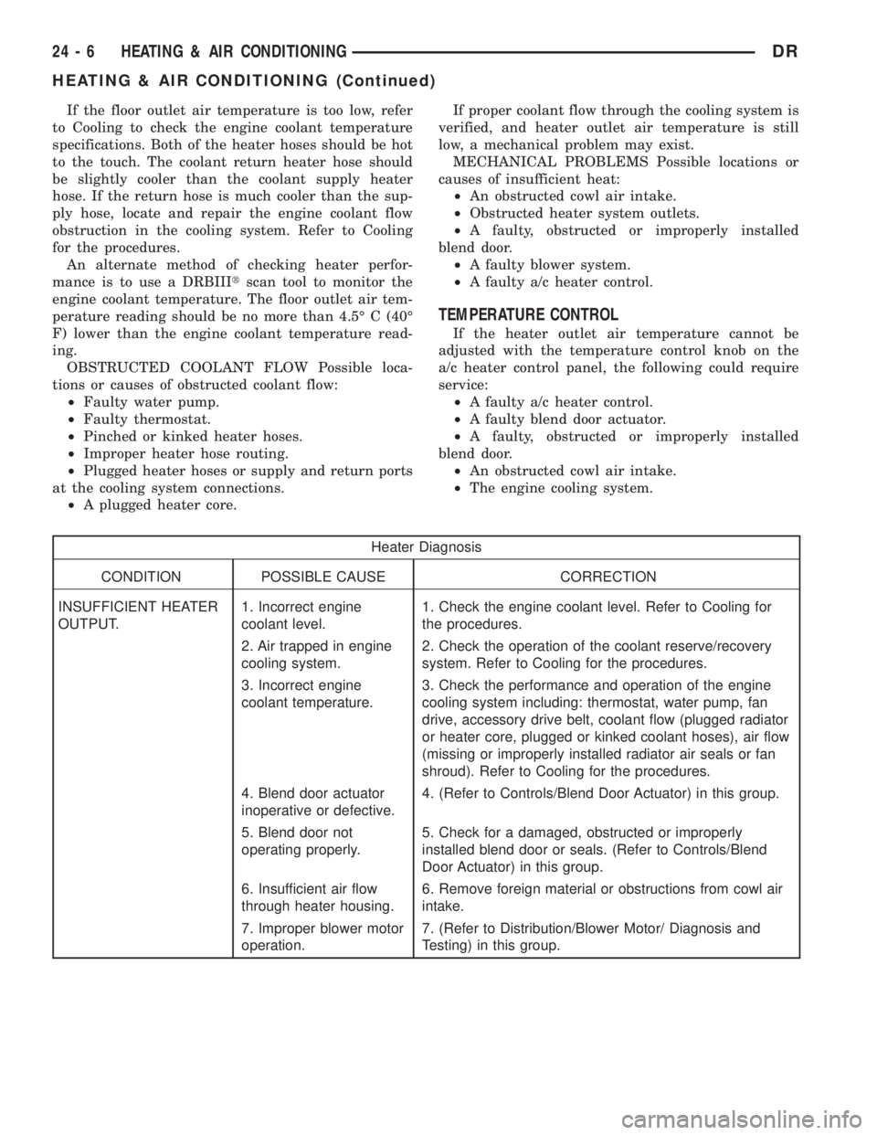
Heater Diagnosis
CONDITION POSSIBLE CAUSE CORRECTION
INSUFFICIENT HEATER
OUTPUT.1. Incorrect engine
coolant level.1. Check the engine coolant level. Refer to Cooling for
the procedures.
2. Air trapped in engine
cooling system.2. Check the operation of the coolant reserve/recovery
system. Refer to Cooling for the procedures.
3. Incorrect engine
coolant temperature.3. Check the performance and operation of the engine
cooling system including: thermostat, water pump, fan
drive, accessory drive belt, coolant flow (plugged radiator
or heater core, plugged or kinked coolant hoses), air flow
(missing or improperly installed radiator air seals or fan
shroud). Refer to Cooling for the procedures.
4. Blend door actuator
inoperative or defective.4. (Refer to Controls/Blend Door Actuator) in this group.
5. Blend door not
operating properly.5. Check for a damaged, obstructed or improperly
installed blend door or seals. (Refer to Controls/Blend
Door Actuator) in this group.
6. Insufficient air flow
through heater housing.6. Remove foreign material or obstructions from cowl air
intake.
7. Improper blower motor
operation.7. (Refer to Distribution/Blower Motor/ Diagnosis and
Testing) in this group.
24 - 6 HEATING & AIR CONDITIONINGDR
HEATING & AIR CONDITIONING (Continued)