2003 DODGE RAM 4 wheel drive actuator
[x] Cancel search: 4 wheel drive actuatorPage 528 of 2895

nated. A red Light Emitting Diode (LED) behind the
cutout in the opaque layer of the overlay causes the
indicator to appear in red through the translucent
outer layer of the overlay when it is illuminated from
behind by the LED, which is soldered onto the
instrument cluster electronic circuit board. The secu-
rity indicator is serviced as a unit with the instru-
ment cluster.
OPERATION
The security indicator gives an indication to the
vehicle operator when the Vehicle Theft Security Sys-
tem (VTSS) is arming or is armed. On models
equipped with the Sentry Key Immobilizer System
(SKIS), the security indicator also gives an indication
to the vehicle operator of the status of the SKIS. This
indicator is controlled by a transistor on the instru-
ment cluster circuit board based upon cluster pro-
gramming, hard wired inputs to the cluster from the
various security system components, electronic mes-
sages received by the cluster from the Remote Key-
less Entry (RKE) receiver module over a dedicated
serial bus, and electronic messages received by the
cluster from the Sentry Key Immobilizer Module
(SKIM) over the Programmable Communications
Interface (PCI) data bus. The security indicator Light
Emitting Diode (LED) is completely controlled by the
instrument cluster logic circuit, and that logic will
allow this indicator to operate whenever the instru-
ment cluster receives a battery current input on the
fused B(+) circuit. Therefore, the LED can be illumi-
nated regardless of the ignition switch position. The
LED only illuminates when it is provided a path to
ground by the instrument cluster transistor. The
instrument cluster will turn on the security indicator
for the following reasons:
²Bulb Test- Each time the ignition switch is
turned to the On position, the SKIM tells the cluster
to illuminate the SKIS indicator for about two sec-
onds as a bulb test.
²VTSS Indication- During the sixteen second
VTSS arming function, the cluster will flash the
security indicator on and off repeatedly at a steady,
fast rate to indicate that the VTSS is in the process
of arming. Following successful VTSS arming, the
cluster flashes the security indicator on and off con-
tinuously at a slower rate to indicate that the VTSS
is armed. The security indicator continues flashing at
the slower rate until the VTSS is disarmed or trig-
gered. If the VTSS has alarmed and rearmed, the
cluster will flash the security indicator at a steady,
slow rate for about thirty seconds after the VTSS is
disarmed.
²SKIM Lamp-On Message- Each time the clus-
ter receives a lamp-on message from the SKIM, the
security indicator will be illuminated. The indicatorcan be flashed on and off, or illuminated solid, as dic-
tated by the SKIM message. The indicator remains
illuminated solid or continues to flash until the clus-
ter receives a lamp-off message from the SKIM, or
until the ignition switch is turned to the Off position,
whichever occurs first. For more information on the
SKIS and the security indicator control parameters,
(Refer to 8 - ELECTRICAL/VEHICLE THEFT SECU-
RITY/SENTRY KEY IMMOBILIZER SYSTEM -
OPERATION).
²Communication Error- If the cluster receives
no SKIS lamp-on or lamp-off messages from the
SKIM for twenty consecutive seconds, the SKIS indi-
cator is illuminated by the instrument cluster. The
indicator remains controlled and illuminated by the
cluster until a valid SKIS lamp-on or lamp-off mes-
sage is received from the SKIM.
²Actuator Test- Each time the instrument clus-
ter is put through the actuator test, the security indi-
cator will be turned on, then off again during the
bulb check portion of the test to confirm the function-
ality of the LED and the cluster control circuitry.
The instrument cluster circuitry controls the secu-
rity indicator whenever the ignition switch is in the
Off position and the VTSS is arming, armed, or
alarming. Whenever the ignition switch is in the On
or Start positions, the SKIM performs a self-test to
decide whether the SKIS is in good operating condi-
tion and whether a valid key is present in the igni-
tion lock cylinder. The SKIM then sends the proper
lamp-on or lamp-off messages to the instrument clus-
ter. For further diagnosis of the security indicator or
the instrument cluster circuitry that controls the
indicator, (Refer to 8 - ELECTRICAL/INSTRUMENT
CLUSTER - DIAGNOSIS AND TESTING). If the
instrument cluster flashes the SKIS indicator upon
ignition On, or turns on the SKIS indicator solid
after the bulb test, it indicates that a SKIS malfunc-
tion has occurred or that the SKIS is inoperative. For
proper diagnosis of the VTSS, the SKIS, the SKIM,
the PCI data bus, or the electronic message inputs to
the instrument cluster that control the security indi-
cator, a DRBIIItscan tool is required. Refer to the
appropriate diagnostic information.
SERVICE 4WD INDICATOR
DESCRIPTION
A service 4WD indicator is standard equipment on
all instrument clusters. However, on vehicles not
equipped with the optional four-wheel drive system
and electronically shifted transfer case, this indicator
is electronically disabled. The service 4WD indicator
consists of the words ªSERVICE 4x4º, which appears
in the lower portion of the odometer/trip odometer
DRINSTRUMENT CLUSTER 8J - 35
SECURITY INDICATOR (Continued)
Page 620 of 2895

ber boot is installed over the engagement dowel to
eliminate contact noise between the dowel and the
steering wheel. The two lobes on the turn signal can-
cel cam on the lower surface of the clockspring rotor
hub contact a turn signal cancel actuator of the
multi-function switch to provide automatic turn sig-
nal cancellation. The yellow sleeved pigtail wires on
the upper surface of the clockspring rotor connect the
clockspring to the driver airbag, while a steering
wheel wire harness connects the two connector recep-
tacles on the upper surface of the clockspring rotor to
the horn switch feed pigtail wire connector and, if
the vehicle is so equipped, to the optional speed con-
trol and remote radio switches on the steering wheel.
Like the clockspring in a timepiece, the clockspring
tape has travel limits and can be damaged by being
wound too tightly during full stop-to-stop steering
wheel rotation. To prevent this from occurring, the
clockspring is centered when it is installed on the
steering column. Centering the clockspring indexes
the clockspring tape to the movable steering compo-
nents so that the tape can operate within its
designed travel limits. However, if the clockspring is
removed from the steering column or if the steering
shaft is disconnected from the steering gear, the
clockspring spool can change position relative to the
movable steering components. The clockspring must
be re-centered following completion of this service or
the tape may be damaged.
Service replacement clocksprings are shipped pre-
centered and with a plastic locking pin installed.
This locking pin should not be disengaged until the
clockspring has been installed on the steering col-
umn. If the locking pin is removed or damaged before
the clockspring is installed on a steering column, the
clockspring centering procedure must be performed.
(Refer to 8 - ELECTRICAL/RESTRAINTS/CLOCK-
SPRING - STANDARD PROCEDURE - CLOCK-
SPRING CENTERING).
STANDARD PROCEDURE - CLOCKSPRING
CENTERING
The clockspring is designed to wind and unwind
when the steering wheel is rotated, but is only
designed to rotate the same number of turns (about
five complete rotations) as the steering wheel can be
turned from stop to stop. Centering the clockspring
indexes the clockspring tape to other steering compo-
nents so that it can operate within its designed
travel limits. The rotor of a centered clockspring can
be rotated two and one-half turns in either direction
from the centered position, without damaging the
clockspring tape.
However, if the clockspring is removed for service
or if the steering column is disconnected from the
steering gear, the clockspring tape can change posi-tion relative to the other steering components. The
clockspring must then be re-centered following com-
pletion of such service or the clockspring tape may be
damaged. Service replacement clocksprings are
shipped pre-centered, with a plastic locking pin
installed (Fig. 19). This locking pin should not be
removed until the clockspring has been installed on
the steering column. If the locking pin is removed
before the clockspring is installed on a steering col-
umn, the clockspring centering procedure must be
performed.
WARNING: ON VEHICLES EQUIPPED WITH AIR-
BAGS, DISABLE THE SUPPLEMENTAL RESTRAINT
SYSTEM BEFORE ATTEMPTING ANY STEERING
WHEEL, STEERING COLUMN, DRIVER AIRBAG,
PASSENGER AIRBAG, SEAT BELT TENSIONER,
SIDE CURTAIN AIRBAG, OR INSTRUMENT PANEL
COMPONENT DIAGNOSIS OR SERVICE. DISCON-
NECT AND ISOLATE THE BATTERY NEGATIVE
(GROUND) CABLE, THEN WAIT TWO MINUTES FOR
THE SYSTEM CAPACITOR TO DISCHARGE BEFORE
PERFORMING FURTHER DIAGNOSIS OR SERVICE.
THIS IS THE ONLY SURE WAY TO DISABLE THE
SUPPLEMENTAL RESTRAINT SYSTEM. FAILURE TO
TAKE THE PROPER PRECAUTIONS COULD
RESULT IN ACCIDENTAL AIRBAG DEPLOYMENT
AND POSSIBLE PERSONAL INJURY.
Fig. 19 Clockspring and Multi-Function Switch
1 - CLOCKSPRING
2 - LOCATING PIN
3 - SCREW (2)
4 - LOCKING PIN
5 - ENGAGEMENT DOWEL BOOT
DRRESTRAINTS 8O - 19
CLOCKSPRING (Continued)
Page 721 of 2895

Component Page
Overdrive Switch...................... 8W-31
Overhead Map/Reading Lamp............ 8W-44
Oxygen Sensors....................... 8W-30
Oxygen Sensor Downstream Relay........ 8W-30
Park Brake Switch.................... 8W-40
Park Lamp Relay................... 8W-50, 52
Park/Turn Signal Lamps............. 8W-50, 52
Passenger Airbag On/Off Switch.......... 8W-43
Blend Door Actuators.................. 8W-42
Passenger Lumbar Switch............... 8W-63
Power Mirrors........................ 8W-62
Power Outlet......................... 8W-41
Power Outlet-Console.................. 8W-41
Power Seat Motors.................... 8W-63
Power Seat Switches................... 8W-63
Power Steering Pressure Switch.......... 8W-30
Power Window Circuit Breaker........... 8W-10
Power Window Motors.................. 8W-60
Power Window Switches................ 8W-60
Powertrain Control Module.............. 8W-30
PTCs............................... 8W-10
PTO Switch.......................... 8W-30
Radio............................... 8W-47
Recirculation Door Actuator............. 8W-42
Red Brake Warning Indicator Switch . . . 8W-34, 35
Remote Radio Switches................. 8W-47
Splices.............................. 8W-70
Seat Belt Pretensioners................. 8W-43
Seat Belt Switch-Driver................ 8W-40
Seat Belt Tensioner Reducer............. 8W-40
Seat Heater Interface Module............ 8W-63
Sentry Key Immobilizer Module.......... 8W-39
Spare Relay.......................... 8W-10
Speakers............................ 8W-47Component Page
Speed Control Servo................... 8W-33
Speed Control Switches................. 8W-33
Starter Motor Relay................... 8W-21
Starter Motor.................... 8W-21, 21-3
Tail/Stop Lamps...................... 8W-52
Tail/Stop/Turn Signal Lamps.......... 8W-51, 52
Tail/Turn Lamps...................... 8W-52
Tailgate Lamp Assembly................ 8W-51
Throttle Position Sensor................ 8W-30
Throttle Position Switch................ 8W-30
Trailer Tow Connector.................. 8W-54
Trailer Tow Connector-Add On........... 8W-54
Trailer Tow Left Turn Relay............. 8W-54
Trailer Tow Right Turn Relay............ 8W-54
Transfer Case Control Module............ 8W-31
Transfer Case Mode Sensor.............. 8W-31
Transfer Case Selector Switch............ 8W-31
Transfer Case Shift Motor............... 8W-31
Transmission Control Module............ 8W-31
Transmission Control Relay............. 8W-31
Transmission Range Sensor.............. 8W-31
Transmission Solenoid Assembly.......... 8W-31
Transmission Solenoid/TRS Assembly...... 8W-31
Underhood Lamp...................... 8W-44
Vacuum Pump........................ 8W-30
Vehicle Speed Sensor................... 8W-30
Vistronic Fan Drive.................... 8W-30
Washer Fluid Level Switch.............. 8W-53
Washer Pump Motor-Front.............. 8W-53
Water In Fuel Sensor.................. 8W-30
Wheel Speed Sensors................... 8W-35
Wiper High/Low Relay................. 8W-53
Wiper Motor-Front.................... 8W-53
8W - 02 - 2 8W-02 COMPONENT INDEXDR
Page 1178 of 2895
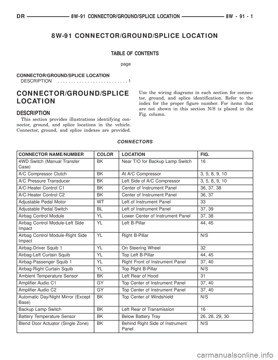
8W-91 CONNECTOR/GROUND/SPLICE LOCATION
TABLE OF CONTENTS
page
CONNECTOR/GROUND/SPLICE LOCATION
DESCRIPTION..........................1
CONNECTOR/GROUND/SPLICE
LOCATION
DESCRIPTION
This section provides illustrations identifying con-
nector, ground, and splice locations in the vehicle.
Connector, ground, and splice indexes are provided.Use the wiring diagrams in each section for connec-
tor, ground, and splice identification. Refer to the
index for the proper figure number. For items that
are not shown in this section N/S is placed in the
Fig. column.
CONNECTORS
CONNECTOR NAME/NUMBER COLOR LOCATION FIG.
4WD Switch (Manual Transfer
Case)BK Near T/O for Backup Lamp Switch 16
A/C Compressor Clutch BK At A/C Compressor 3, 5, 8, 9, 10
A/C Pressure Transducer BK Left Side of A/C Compressor 3, 5, 8, 9, 10
A/C-Heater Control C1 BK Center of Instrument Panel 36, 37, 38
A/C-Heater Control C2 BK Center of Instrument Panel 36, 37
Adjustable Pedal Motor WT Left of Instrument Panel 33
Adjustable Pedal Switch BL Left of Instrument Panel 37, 39
Airbag Control Module YL Lower Center of Instrument Panel 37, 38
Airbag Control Module-Left Side
ImpactYL Left B-Pillar 44, 45
Airbag Control Module-Right Side
ImpactYL Right B-Pillar N/S
Airbag-Driver Squib 1 YL On Steering Wheel 32
Airbag-Left Curtain Squib YL Top Left B-Pillar 44, 45
Airbag-Passenger Squib 1 YL Right Front of Instrument Panel 37, 40
Airbag-Right Curtain Squib YL Top Right B-Pillar N/S
Ambient Temperature Sensor BK Left Rear of Hood 31
Amplifier Audio C1 GY Top Center of Instrument Panel 37, 40
Amplifier Audio C2 GY Top Center of Instrument Panel 37, 40
Automatic Day/Night Mirror (Except
Base)BK Top Center of Windshield N/S
Backup Lamp Switch BK Left Rear of Transmission 16
Battery Temperature Sensor BK Below Battery Tray 26, 28, 29, 30
Blend Door Actuator (Single Zone) BK Behind Right Side of Instrument
PanelN/S
DR8W-91 CONNECTOR/GROUND/SPLICE LOCATION 8W - 91 - 1
Page 1184 of 2895
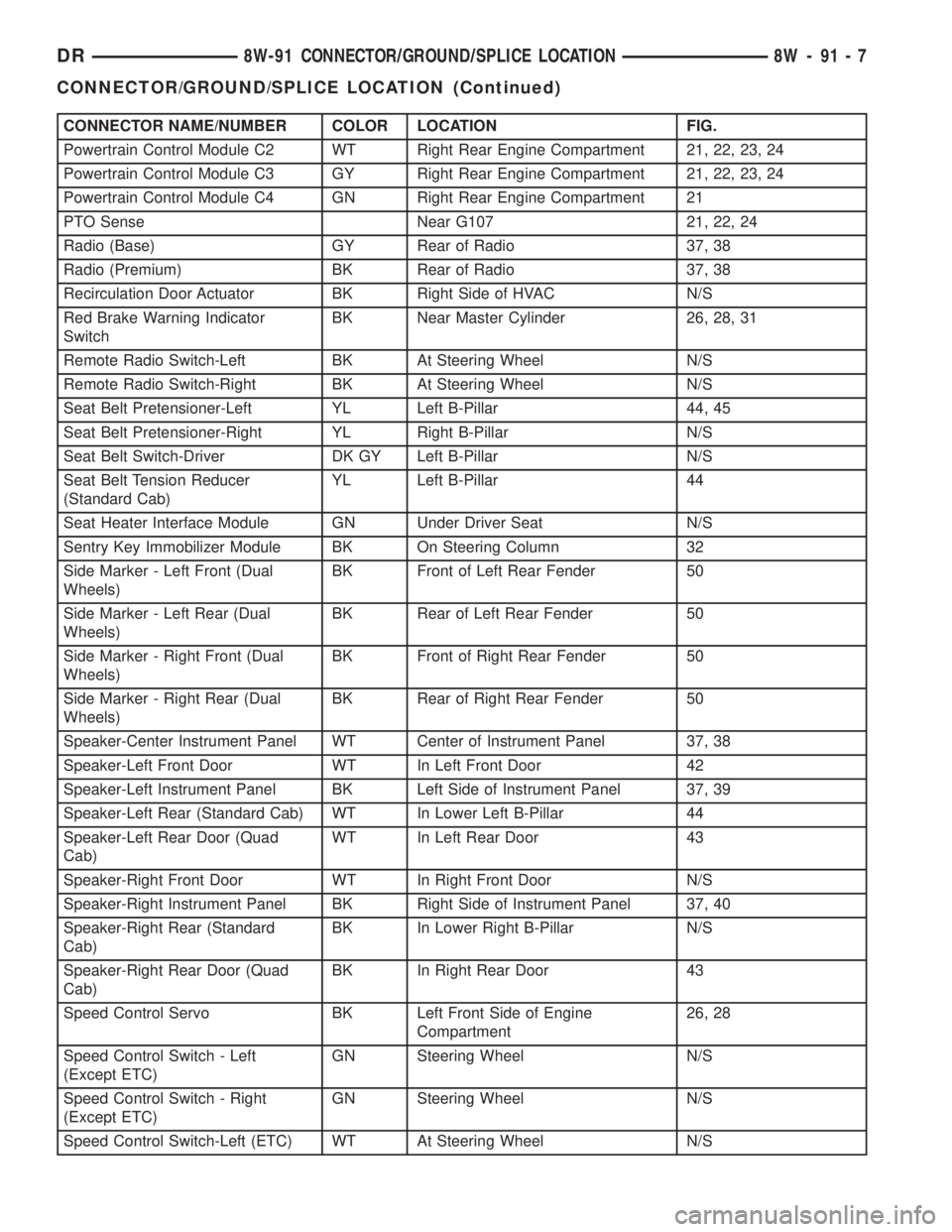
CONNECTOR NAME/NUMBER COLOR LOCATION FIG.
Powertrain Control Module C2 WT Right Rear Engine Compartment 21, 22, 23, 24
Powertrain Control Module C3 GY Right Rear Engine Compartment 21, 22, 23, 24
Powertrain Control Module C4 GN Right Rear Engine Compartment 21
PTO Sense Near G107 21, 22, 24
Radio (Base) GY Rear of Radio 37, 38
Radio (Premium) BK Rear of Radio 37, 38
Recirculation Door Actuator BK Right Side of HVAC N/S
Red Brake Warning Indicator
SwitchBK Near Master Cylinder 26, 28, 31
Remote Radio Switch-Left BK At Steering Wheel N/S
Remote Radio Switch-Right BK At Steering Wheel N/S
Seat Belt Pretensioner-Left YL Left B-Pillar 44, 45
Seat Belt Pretensioner-Right YL Right B-Pillar N/S
Seat Belt Switch-Driver DK GY Left B-Pillar N/S
Seat Belt Tension Reducer
(Standard Cab)YL Left B-Pillar 44
Seat Heater Interface Module GN Under Driver Seat N/S
Sentry Key Immobilizer Module BK On Steering Column 32
Side Marker - Left Front (Dual
Wheels)BK Front of Left Rear Fender 50
Side Marker - Left Rear (Dual
Wheels)BK Rear of Left Rear Fender 50
Side Marker - Right Front (Dual
Wheels)BK Front of Right Rear Fender 50
Side Marker - Right Rear (Dual
Wheels)BK Rear of Right Rear Fender 50
Speaker-Center Instrument Panel WT Center of Instrument Panel 37, 38
Speaker-Left Front Door WT In Left Front Door 42
Speaker-Left Instrument Panel BK Left Side of Instrument Panel 37, 39
Speaker-Left Rear (Standard Cab) WT In Lower Left B-Pillar 44
Speaker-Left Rear Door (Quad
Cab)WT In Left Rear Door 43
Speaker-Right Front Door WT In Right Front Door N/S
Speaker-Right Instrument Panel BK Right Side of Instrument Panel 37, 40
Speaker-Right Rear (Standard
Cab)BK In Lower Right B-Pillar N/S
Speaker-Right Rear Door (Quad
Cab)BK In Right Rear Door 43
Speed Control Servo BK Left Front Side of Engine
Compartment26, 28
Speed Control Switch - Left
(Except ETC)GN Steering Wheel N/S
Speed Control Switch - Right
(Except ETC)GN Steering Wheel N/S
Speed Control Switch-Left (ETC) WT At Steering Wheel N/S
DR8W-91 CONNECTOR/GROUND/SPLICE LOCATION 8W - 91 - 7
CONNECTOR/GROUND/SPLICE LOCATION (Continued)
Page 1800 of 2895
NOTE: When servicing the coupler a new bolt must
be used when installing.
DIAGNOSIS AND TESTING - STEERING
COLUMN
If the vehicle is involved in a front end collision/the
air bag has deployed the column must be inspected.
This inspection will determine if the Column has col-
lapsed. Inspect the column mounting capsules visu-
ally and manually push and pull them to check for
separation or fractures. If capsules are fractured or
have moved the column MUST be replaced.
REMOVAL
WARNING: BEFORE SERVICING THE STEERING
COLUMN THE AIRBAG SYSTEM MUST BE DIS-
ARMED. REFER TO ELECTRICAL RESTRAINT SYS-
TEM FOR SERVICE PROCEDURES. FAILURE TO DO
SO MAY RESULT IN ACCIDENTAL DEPLOYMENT OF
THE AIRBAG AND POSSIBLE PERSONAL INJURY.
CAUTION: All fasteners must be torqued to specifi-
cation to ensure proper operation of the steering
column.(1) Position the front wheelsstraight ahead.
(2) Disconnect the negative (ground) cable from
the battery.
(3) Remove the two switches from the steering
wheel.
(4) Remove the airbag, (Refer to 8 - ELECTRICAL/
RESTRAINTS/DRIVER AIRBAG - REMOVAL).
(5) Remove the steering wheel with special tool
CJ98±1 or an appropriate steering wheel puller.
CAUTION: Ensure the puller bolts are fully engaged
into the steering wheel and not into the clock-
spring, before attempting to remove the wheel. Fail-
ure to do so may damage the steering wheel/
clockspring.
(6) Remove the steering column opening cover
(Refer to 23 - BODY/INSTRUMENT PANEL/STEER-
ING COLUMN OPENING COVER - REMOVAL).
(7) Remove the tilt lever.
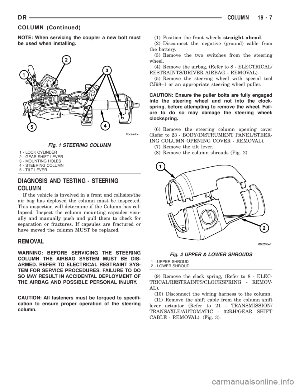
(8) Remove the column shrouds (Fig. 2).
(9) Remove the clock spring, (Refer to 8 - ELEC-
TRICAL/RESTRAINTS/CLOCKSPRING - REMOV-
AL).
(10) Disconnect the wiring harness to the column.
(11) Remove the shift cable from the column shift
lever actuator (Refer to 21 - TRANSMISSION/
TRANSAXLE/AUTOMATIC - 32RH/GEAR SHIFT
CABLE - REMOVAL). (Fig. 3).
Fig. 1 STEERING COLUMN
1 - LOCK CYLINDER
2 - GEAR SHIFT LEVER
3 - MOUNTING HOLES
4 - STEERING COLUMN
5 - TILT LEVER
Fig. 2 UPPER & LOWER SHROUDS
1 - UPPER SHROUD
2 - LOWER SHROUD
DRCOLUMN 19 - 7
COLUMN (Continued)
Page 2784 of 2895
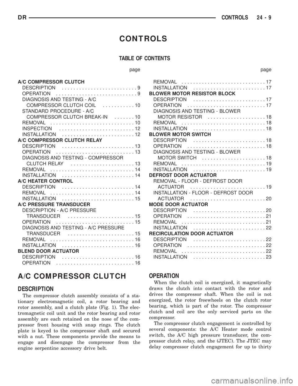
CONTROLS
TABLE OF CONTENTS
page page
A/C COMPRESSOR CLUTCH
DESCRIPTION..........................9
OPERATION............................9
DIAGNOSIS AND TESTING - A/C
COMPRESSOR CLUTCH COIL...........10
STANDARD PROCEDURE - A/C
COMPRESSOR CLUTCH BREAK-IN.......10
REMOVAL.............................10
INSPECTION..........................12
INSTALLATION.........................12
A/C COMPRESSOR CLUTCH RELAY
DESCRIPTION.........................13
OPERATION...........................13
DIAGNOSIS AND TESTING - COMPRESSOR
CLUTCH RELAY......................13
REMOVAL.............................14
INSTALLATION.........................14
A/C HEATER CONTROL
DESCRIPTION.........................14
REMOVAL.............................14
INSTALLATION.........................15
A/C PRESSURE TRANSDUCER
DESCRIPTION - A/C PRESSURE
TRANSDUCER.......................15
OPERATION...........................15
DIAGNOSIS AND TESTING - A/C PRESSURE
TRANSDUCER.......................15
REMOVAL.............................16
INSTALLATION.........................16
BLEND DOOR ACTUATOR
DESCRIPTION.........................16
OPERATION...........................16REMOVAL.............................17
INSTALLATION.........................17
BLOWER MOTOR RESISTOR BLOCK
DESCRIPTION.........................17
OPERATION...........................17
DIAGNOSIS AND TESTING - BLOWER
MOTOR RESISTOR....................18
REMOVAL.............................18
INSTALLATION.........................18
BLOWER MOTOR SWITCH
DESCRIPTION.........................18
OPERATION...........................18
DIAGNOSIS AND TESTING - BLOWER
MOTOR SWITCH......................18
REMOVAL.............................19
INSTALLATION.........................19
DEFROST DOOR ACTUATOR
REMOVAL - FLOOR - DEFROST DOOR
ACTUATOR..........................19
INSTALLATION - FLOOR - DEFROST DOOR
ACTUATOR..........................20
MODE DOOR ACTUATOR
DESCRIPTION.........................20
OPERATION...........................21
REMOVAL.............................21
INSTALLATION.........................22
RECIRCULATION DOOR ACTUATOR
DESCRIPTION.........................22
OPERATION...........................22
REMOVAL.............................22
INSTALLATION.........................23
A/C COMPRESSOR CLUTCH
DESCRIPTION
The compressor clutch assembly consists of a sta-
tionary electromagnetic coil, a rotor bearing and
rotor assembly, and a clutch plate (Fig. 1). The elec-
tromagnetic coil unit and the rotor bearing and rotor
assembly are each retained on the nose of the com-
pressor front housing with snap rings. The clutch
plate is keyed to the compressor shaft and secured
with a nut. These components provide the means to
engage and disengage the compressor from the
engine serpentine accessory drive belt.
OPERATION
When the clutch coil is energized, it magnetically
draws the clutch into contact with the rotor and
drives the compressor shaft. When the coil is not
energized, the rotor freewheels on the clutch rotor
bearing, which is part of the rotor. The compressor
clutch and coil are the only serviced parts on the
compressor.
The compressor clutch engagement is controlled by
several components: the A/C Heater mode control
switch, the A/C high pressure transducer, the com-
pressor clutch relay, and the (JTEC). The JTEC may
delay compressor clutch engagement for up to thirty
DRCONTROLS 24 - 9
Page 2792 of 2895
trol module learns the blend air door stop positions
during the calibration procedure and will store a
Diagnostic Trouble Code (DTC) for any problems it
detects in the blend door actuator circuits. The blend
door actuator can be diagnosed using a DRBIIItscan
tool. Refer to the appropriate diagnostic information.
REMOVAL
The single zone heating and air conditioning sys-
tem is equipped with a single blend door actuator.
The dual zone system has two blend door actuators,
one for the driver side blend air door and one for the
passenger side blend air door. The same service pro-
cedures can be used for each of these actuators.
WARNING: ON VEHICLES EQUIPPED WITH AIR-
BAGS, DISABLE THE AIRBAG SYSTEM BEFORE
ATTEMPTING ANY STEERING WHEEL, STEERING
COLUMN, OR INSTRUMENT PANEL COMPONENT
DIAGNOSIS OR SERVICE. DISCONNECT AND ISO-
LATE THE BATTERY NEGATIVE (GROUND) CABLE,
THEN WAIT TWO MINUTES FOR THE AIRBAG SYS-
TEM CAPACITOR TO DISCHARGE BEFORE PER-
FORMING FURTHER DIAGNOSIS OR SERVICE. THIS
IS THE ONLY SURE WAY TO DISABLE THE AIRBAG
SYSTEM. FAILURE TO TAKE THE PROPER PRE-
CAUTIONS COULD RESULT IN ACCIDENTAL AIR-
BAG DEPLOYMENT AND POSSIBLE PERSONAL
INJURY.
(1) Disconnect and isolate the battery negative
cable.
(2) Remove the instrument panel assembly(Refer
to 23 - BODY/INSTRUMENT PANEL/INSTRUMENT
PANEL ASSEMBLY - REMOVAL).
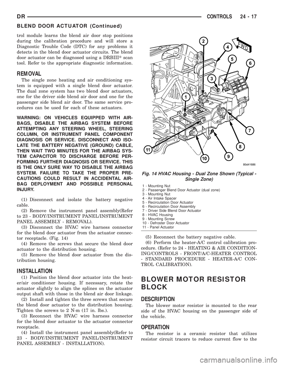
(3) Disconnect the HVAC wire harness connector
for the blend door actuator from the actuator connec-
tor receptacle. (Fig. 14)
(4) Remove the screws that secure the blend door
actuator to the distribution housing.
(5) Remove the blend door actuator from the dis-
tribution housing.
INSTALLATION
(1) Position the blend door actuator into the heat-
er/air conditioner housing. If necessary, rotate the
actuator slightly to align the splines on the actuator
output shaft with those in the blend air door linkage.
(2) Install and tighten the three screws that secure
the blend door actuator to the distribution housing.
Tighten the screws to 2 N´m (17 in. lbs.).
(3) Reconnect the HVAC wire harness connector
for the blend door actuator to the actuator connector
receptacle.
(4) Install the instrument panel assembly(Refer to
23 - BODY/INSTRUMENT PANEL/INSTRUMENT
PANEL ASSEMBLY - INSTALLATION).(5) Reconnect the battery negative cable.
(6) Perform the heater-A/C control calibration pro-
cedure. (Refer to 24 - HEATING & AIR CONDITION-
ING/CONTROLS - FRONT/A/C-HEATER CONTROL
- STANDARD PROCEDURE - HEATER-A/C CON-
TROL CALIBRATION).BLOWER MOTOR RESISTOR
BLOCK
DESCRIPTION
The blower motor resistor is mounted to the rear
side of the HVAC housing on the passenger side of
the vehicle.
OPERATION
The resistor is a ceramic resistor that utilizes
resistor circuit tracers to reduce current flow to the
Fig. 14 HVAC Housing - Dual Zone Shown (Typical -
Single Zone)
1 - Mounting Nut
2 - Passenger Blend Door Actuator (dual zone)
3 - Mounting Nut
4 - Air Intake Spacer
5 - Recirculation Door Actuator
6 - Recirculation Door Assembly
7 - Driver Side Blend Door Actuator
8 - HVAC Housing
9 - Mounting Screw
10 - Defroster Door Actuator
11 - Panel Actuator
DRCONTROLS 24 - 17
BLEND DOOR ACTUATOR (Continued)