2003 DODGE RAM warning
[x] Cancel search: warningPage 653 of 2895
and inert gas canister are sealed and connected to a
tubular manifold so that all of the released gas is
directed into the folded curtain airbag cushion, caus-
ing the cushion to inflate.
As the airbag cushion inflates it will drop down
from the roof rail between the edge of the headliner
and the side glass/body pillars to form a curtain-like
cushion to protect the vehicle occupants during a side
impact collision. The front tether keeps the front por-
tion of the bag taut, thus ensuring that the bag will
deploy in the proper position. Following the airbag
deployment, the airbag cushion quickly deflates by
venting the inert gas through the loose weave of the
cushion fabric, and the deflated cushion hangs down
loosely from the roof rail.
REMOVAL
The following procedure is for replacement of a
faulty or damaged side curtain airbag. If the airbag
is faulty or damaged, but not deployed, review the
recommended procedures for handling non-deployed
supplemental restraints. (Refer to 8 - ELECTRICAL/
RESTRAINTS - STANDARD PROCEDURE - HAN-
DLING NON-DEPLOYED SUPPLEMENTAL
RESTRAINTS). If the side curtain airbag has been
deployed, review the recommended procedures for
service after a supplemental restraint deployment
before removing the airbag from the vehicle. (Refer to
8 - ELECTRICAL/RESTRAINTS - STANDARD PRO-
CEDURE - SERVICE AFTER A SUPPLEMENTAL
RESTRAINT DEPLOYMENT).
WARNING: ON VEHICLES EQUIPPED WITH AIR-
BAGS, DISABLE THE SUPPLEMENTAL RESTRAINT
SYSTEM BEFORE ATTEMPTING ANY STEERING
WHEEL, STEERING COLUMN, DRIVER AIRBAG,
PASSENGER AIRBAG, SEAT BELT TENSIONER,
SIDE CURTAIN AIRBAG, OR INSTRUMENT PANEL
COMPONENT DIAGNOSIS OR SERVICE. DISCON-
NECT AND ISOLATE THE BATTERY NEGATIVE
(GROUND) CABLE, THEN WAIT TWO MINUTES FOR
THE SYSTEM CAPACITOR TO DISCHARGE BEFORE
PERFORMING FURTHER DIAGNOSIS OR SERVICE.
THIS IS THE ONLY SURE WAY TO DISABLE THE
SUPPLEMENTAL RESTRAINT SYSTEM. FAILURE TO
TAKE THE PROPER PRECAUTIONS COULD
RESULT IN ACCIDENTAL AIRBAG DEPLOYMENT
AND POSSIBLE PERSONAL INJURY.
WARNING: WHEN REMOVING A DEPLOYED AIR-
BAG, RUBBER GLOVES, EYE PROTECTION, AND A
LONG-SLEEVED SHIRT SHOULD BE WORN. THERE
MAY BE DEPOSITS ON THE AIRBAG UNIT AND
OTHER INTERIOR SURFACES. IN LARGE DOSES,
THESE DEPOSITS MAY CAUSE IRRITATION TO THE
SKIN AND EYES.WARNING: USE EXTREME CARE TO PREVENT ANY
FOREIGN MATERIAL FROM ENTERING THE SIDE
CURTAIN AIRBAG, OR BECOMING ENTRAPPED
BETWEEN THE SIDE CURTAIN AIRBAG CUSHION
AND THE HEADLINER. FAILURE TO OBSERVE THIS
WARNING COULD RESULT IN OCCUPANT INJURIES
UPON AIRBAG DEPLOYMENT.
(1) Disconnect and isolate the battery negative
cable. Wait two minutes for the system capacitor to
discharge before further service.
(2) Remove the headliner from the vehicle. (Refer
to 23 - BODY/INTERIOR/HEADLINER - REMOV-
AL).
(3) Remove the screw that secures the side curtain
airbag tether retainer to the base of the A-pillar near
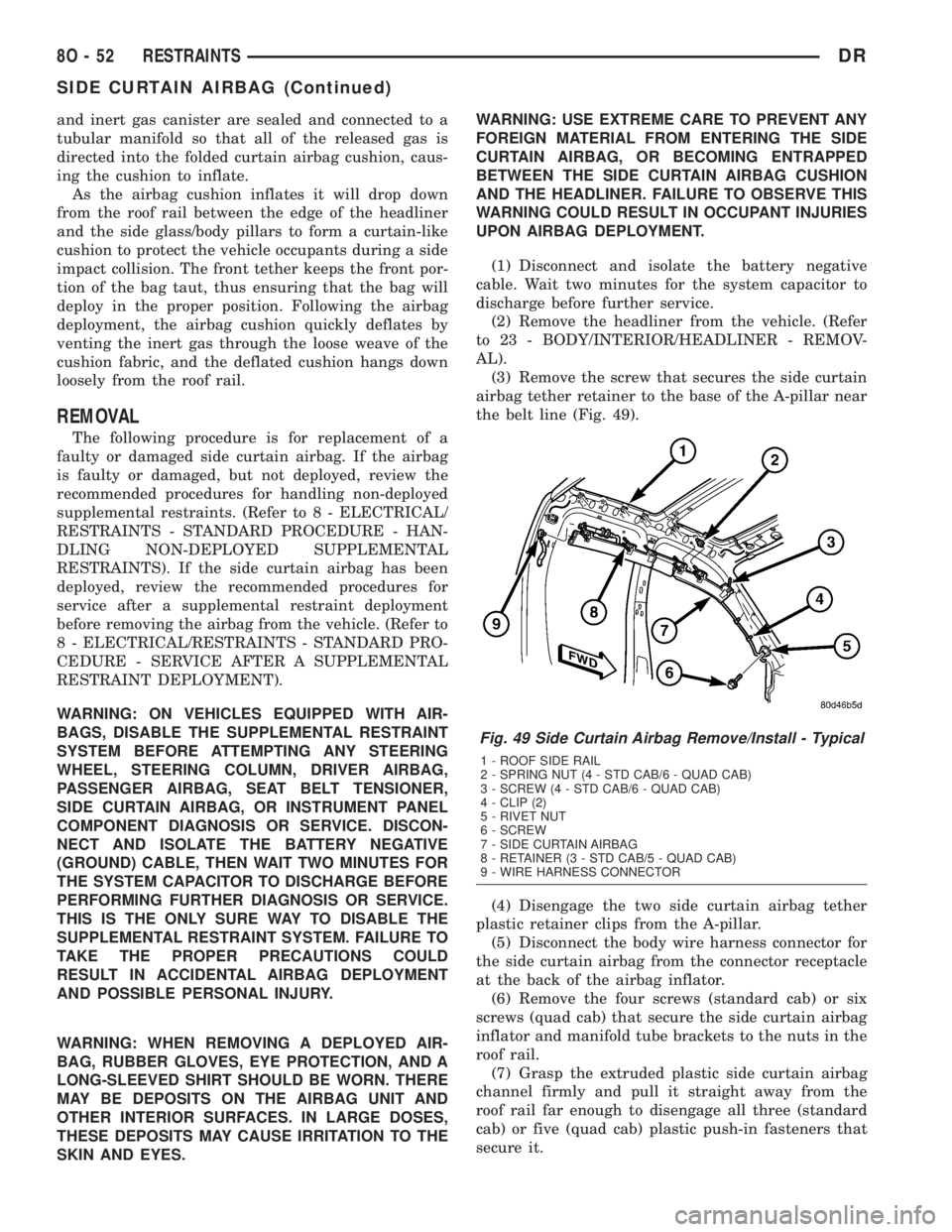
the belt line (Fig. 49).
(4) Disengage the two side curtain airbag tether
plastic retainer clips from the A-pillar.
(5) Disconnect the body wire harness connector for
the side curtain airbag from the connector receptacle
at the back of the airbag inflator.
(6) Remove the four screws (standard cab) or six
screws (quad cab) that secure the side curtain airbag
inflator and manifold tube brackets to the nuts in the
roof rail.
(7) Grasp the extruded plastic side curtain airbag
channel firmly and pull it straight away from the
roof rail far enough to disengage all three (standard
cab) or five (quad cab) plastic push-in fasteners that
secure it.
Fig. 49 Side Curtain Airbag Remove/Install - Typical
1 - ROOF SIDE RAIL
2 - SPRING NUT (4 - STD CAB/6 - QUAD CAB)
3 - SCREW (4 - STD CAB/6 - QUAD CAB)
4 - CLIP (2)
5 - RIVET NUT
6 - SCREW
7 - SIDE CURTAIN AIRBAG
8 - RETAINER (3 - STD CAB/5 - QUAD CAB)
9 - WIRE HARNESS CONNECTOR
8O - 52 RESTRAINTSDR
SIDE CURTAIN AIRBAG (Continued)
Page 654 of 2895
(8) Remove the side curtain airbag from the vehi-
cle as a unit.
INSTALLATION
The following procedure is for replacement of a
faulty or damaged side curtain airbag. If the airbag
is faulty or damaged, but not deployed, review the
recommended procedures for handling non-deployed
supplemental restraints. (Refer to 8 - ELECTRICAL/
RESTRAINTS - STANDARD PROCEDURE - HAN-
DLING NON-DEPLOYED SUPPLEMENTAL
RESTRAINTS). If the side curtain airbag has been
deployed, review the recommended procedures for
service after a supplemental restraint deployment
before removing the airbag from the vehicle. (Refer to
8 - ELECTRICAL/RESTRAINTS - STANDARD PRO-
CEDURE - SERVICE AFTER A SUPPLEMENTAL
RESTRAINT DEPLOYMENT).
WARNING: ON VEHICLES EQUIPPED WITH AIR-
BAGS, DISABLE THE SUPPLEMENTAL RESTRAINT
SYSTEM BEFORE ATTEMPTING ANY STEERING
WHEEL, STEERING COLUMN, DRIVER AIRBAG,
PASSENGER AIRBAG, SEAT BELT TENSIONER,
SIDE CURTAIN AIRBAG, OR INSTRUMENT PANEL
COMPONENT DIAGNOSIS OR SERVICE. DISCON-
NECT AND ISOLATE THE BATTERY NEGATIVE
(GROUND) CABLE, THEN WAIT TWO MINUTES FOR
THE SYSTEM CAPACITOR TO DISCHARGE BEFORE
PERFORMING FURTHER DIAGNOSIS OR SERVICE.
THIS IS THE ONLY SURE WAY TO DISABLE THE
SUPPLEMENTAL RESTRAINT SYSTEM. FAILURE TO
TAKE THE PROPER PRECAUTIONS COULD
RESULT IN ACCIDENTAL AIRBAG DEPLOYMENT
AND POSSIBLE PERSONAL INJURY.
WARNING: WHEN REMOVING A DEPLOYED AIR-
BAG, RUBBER GLOVES, EYE PROTECTION, AND A
LONG-SLEEVED SHIRT SHOULD BE WORN. THERE
MAY BE DEPOSITS ON THE AIRBAG UNIT AND
OTHER INTERIOR SURFACES. IN LARGE DOSES,
THESE DEPOSITS MAY CAUSE IRRITATION TO THE
SKIN AND EYES.
WARNING: USE EXTREME CARE TO PREVENT ANY
FOREIGN MATERIAL FROM ENTERING THE SIDE
CURTAIN AIRBAG, OR BECOMING ENTRAPPED
BETWEEN THE SIDE CURTAIN AIRBAG CUSHION
AND THE HEADLINER. FAILURE TO OBSERVE THIS
WARNING COULD RESULT IN OCCUPANT INJURIES
UPON AIRBAG DEPLOYMENT.
(1) Position the side curtain airbag into the vehicle
as a unit.
(2) Align all three (standard cab) or five (quad cab)
plastic push-in fasteners that secure the extrudedplastic side curtain airbag channel with their holes
in the roof side rail and push them straight into the
roof rail until they are fully seated (Fig. 49).
(3) Working from the rear of the vehicle to the
front, install and tighten the four screws (standard
cab) or six screws (quad cab) that secure the side cur-
tain airbag inflator and manifold tube brackets to the
nuts in the roof rail. Tighten the screws to 5 N´m (40
in. lbs.).
(4) Reconnect the body wire harness connector for
the side curtain airbag to the connector receptacle at
the back of the airbag inflator. Be certain the connec-
tor is fully engaged and latched.
(5) Engage the two side curtain airbag tether plas-
tic retainer clips into the A-pillar.
(6) Install and tighten the screw that secures the
side curtain airbag tether retainer to the base of the
A-pillar near the belt line. Tighten the screw to 6
N´m (55 in. lbs.).
(7) Reinstall the headliner into the vehicle. (Refer
to 23 - BODY/INTERIOR/HEADLINER - INSTALLA-
TION).
(8) Do not reconnect the battery negative cable at
this time. The supplemental restraint system verifi-
cation test procedure should be performed following
service of any supplemental restraint system compo-
nent. (Refer to 8 - ELECTRICAL/RESTRAINTS -
STANDARD PROCEDURE - VERIFICATION TEST).
SIDE IMPACT AIRBAG
CONTROL MODULE
DESCRIPTION
On vehicles equipped with the optional side curtain
airbags, a Side Impact Airbag Control Module
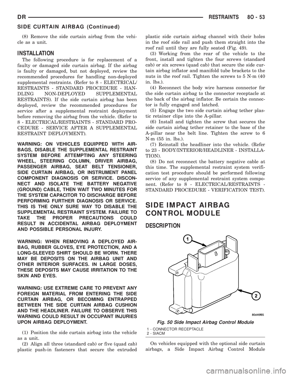
Fig. 50 Side Impact Airbag Control Module
1 - CONNECTOR RECEPTACLE
2 - SIACM
DRRESTRAINTS 8O - 53
SIDE CURTAIN AIRBAG (Continued)
Page 656 of 2895

REMOVAL
REMOVAL
WARNING: ON VEHICLES EQUIPPED WITH AIR-
BAGS, DISABLE THE SUPPLEMENTAL RESTRAINT
SYSTEM BEFORE ATTEMPTING ANY STEERING
WHEEL, STEERING COLUMN, DRIVER AIRBAG,
PASSENGER AIRBAG, SEAT BELT TENSIONER,
SIDE CURTAIN AIRBAG, OR INSTRUMENT PANEL
COMPONENT DIAGNOSIS OR SERVICE. DISCON-
NECT AND ISOLATE THE BATTERY NEGATIVE
(GROUND) CABLE, THEN WAIT TWO MINUTES FOR
THE SYSTEM CAPACITOR TO DISCHARGE BEFORE
PERFORMING FURTHER DIAGNOSIS OR SERVICE.
THIS IS THE ONLY SURE WAY TO DISABLE THE
SUPPLEMENTAL RESTRAINT SYSTEM. FAILURE TO
TAKE THE PROPER PRECAUTIONS COULD
RESULT IN ACCIDENTAL AIRBAG DEPLOYMENT
AND POSSIBLE PERSONAL INJURY.
WARNING: THE SIDE IMPACT AIRBAG CONTROL
MODULE CONTAINS THE IMPACT SENSOR, WHICH
ENABLES THE SYSTEM TO DEPLOY THE SIDE
CURTAIN AIRBAGS. NEVER STRIKE OR DROP THE
SIDE IMPACT AIRBAG CONTROL MODULE, AS IT
CAN DAMAGE THE IMPACT SENSOR OR AFFECT
ITS CALIBRATION. IF A SIDE IMPACT AIRBAG CON-
TROL MODULE IS ACCIDENTALLY DROPPED DUR-
ING SERVICE, THE MODULE MUST BE SCRAPPED
AND REPLACED WITH A NEW UNIT. FAILURE TO
OBSERVE THIS WARNING COULD RESULT IN ACCI-
DENTAL, INCOMPLETE, OR IMPROPER SIDE CUR-
TAIN AIRBAG DEPLOYMENT AND POSSIBLE
OCCUPANT INJURIES.
(1) Adjust the front seat to its most forward posi-
tion for easiest access to the lower B-pillar trim.
(2) Disconnect and isolate the battery negative
cable. Wait two minutes for the system capacitor to
discharge before further service.
(3) Remove the front outboard seat belt and retrac-
tor from the inside of the B-pillar. (Refer to 8 -
ELECTRICAL/RESTRAINTS/FRONT OUTBOARD
SEAT BELT & RETRACTOR - REMOVAL - STAN-
DARD CAB).
(4) Remove the four screws that secure the Side
Impact Airbag Control Module (SIACM) mounting
bracket to the inside of the B-pillar (Fig. 51).
(5) Reach through the retractor mounting hole in
the inner B-pillar to access and disengage the two
plastic push-in fasteners that secure the SIACM to
the inside of the B-pillar.(6) Pull the SIACM and mounting bracket out
through the retractor mounting hole far enough to
access and disconnect the body wire harness connec-
tor for the SIACM from the module connector recep-
tacle.
(7) Remove the SIACM and its mounting bracket
from the B-pillar as a unit.
REMOVAL
WARNING: ON VEHICLES EQUIPPED WITH AIR-
BAGS, DISABLE THE SUPPLEMENTAL RESTRAINT
SYSTEM BEFORE ATTEMPTING ANY STEERING
WHEEL, STEERING COLUMN, DRIVER AIRBAG,
PASSENGER AIRBAG, SEAT BELT TENSIONER,
SIDE CURTAIN AIRBAG, OR INSTRUMENT PANEL
COMPONENT DIAGNOSIS OR SERVICE. DISCON-
NECT AND ISOLATE THE BATTERY NEGATIVE
(GROUND) CABLE, THEN WAIT TWO MINUTES FOR
THE SYSTEM CAPACITOR TO DISCHARGE BEFORE
PERFORMING FURTHER DIAGNOSIS OR SERVICE.
THIS IS THE ONLY SURE WAY TO DISABLE THE
SUPPLEMENTAL RESTRAINT SYSTEM. FAILURE TO
TAKE THE PROPER PRECAUTIONS COULD
RESULT IN ACCIDENTAL AIRBAG DEPLOYMENT
AND POSSIBLE PERSONAL INJURY.
Fig. 51 Side Impact Airbag Control Module
Remove/Install - Std Cab
1 - B-PILLAR
2 - SCREW (4)
3 - FASTENER (2)
4 - BRACKET
5 - SIACM
6 - WIRE HARNESS CONNECTOR
DRRESTRAINTS 8O - 55
SIDE IMPACT AIRBAG CONTROL MODULE (Continued)
Page 657 of 2895

WARNING: THE SIDE IMPACT AIRBAG CONTROL
MODULE CONTAINS THE IMPACT SENSOR, WHICH
ENABLES THE SYSTEM TO DEPLOY THE SIDE
CURTAIN AIRBAGS. NEVER STRIKE OR DROP THE
SIDE IMPACT AIRBAG CONTROL MODULE, AS IT
CAN DAMAGE THE IMPACT SENSOR OR AFFECT
ITS CALIBRATION. IF A SIDE IMPACT AIRBAG CON-
TROL MODULE IS ACCIDENTALLY DROPPED DUR-
ING SERVICE, THE MODULE MUST BE SCRAPPED
AND REPLACED WITH A NEW UNIT. FAILURE TO
OBSERVE THIS WARNING COULD RESULT IN ACCI-
DENTAL, INCOMPLETE, OR IMPROPER SIDE CUR-
TAIN AIRBAG DEPLOYMENT AND POSSIBLE
OCCUPANT INJURIES.
(1) Adjust the front seat to its most forward posi-
tion for easiest access to the lower B-pillar trim.
(2) Disconnect and isolate the battery negative
cable. Wait two minutes for the system capacitor to
discharge before further service.
(3) Remove the front outboard seat belt and retrac-
tor from the inside of the B-pillar. (Refer to 8 -
ELECTRICAL/RESTRAINTS/FRONT OUTBOARD
SEAT BELT & RETRACTOR - REMOVAL - QUAD
CAB).
(4) Remove the four screws that secure the Side
Impact Airbag Control Module (SIACM) mounting
bracket to the inside of the B-pillar (Fig. 52).(5) Reach through the retractor mounting hole in
the inner B-pillar to access the SIACM and lift it
upward far enough to disengage the hook on the
mounting bracket from the slot on the inner B-pillar.
(6) Pull the SIACM and mounting bracket out
through the retractor mounting hole far enough to
access and disconnect the body wire harness connec-
tor for the SIACM from the module connector recep-
tacle.
(7) Remove the SIACM and its mounting bracket
from the B-pillar as a unit.
INSTALLATION
INSTALLATION
WARNING: ON VEHICLES EQUIPPED WITH AIR-
BAGS, DISABLE THE SUPPLEMENTAL RESTRAINT
SYSTEM BEFORE ATTEMPTING ANY STEERING
WHEEL, STEERING COLUMN, DRIVER AIRBAG,
PASSENGER AIRBAG, SEAT BELT TENSIONER,
SIDE CURTAIN AIRBAG, OR INSTRUMENT PANEL
COMPONENT DIAGNOSIS OR SERVICE. DISCON-
NECT AND ISOLATE THE BATTERY NEGATIVE
(GROUND) CABLE, THEN WAIT TWO MINUTES FOR
THE SYSTEM CAPACITOR TO DISCHARGE BEFORE
PERFORMING FURTHER DIAGNOSIS OR SERVICE.
THIS IS THE ONLY SURE WAY TO DISABLE THE
SUPPLEMENTAL RESTRAINT SYSTEM. FAILURE TO
TAKE THE PROPER PRECAUTIONS COULD
RESULT IN ACCIDENTAL AIRBAG DEPLOYMENT
AND POSSIBLE PERSONAL INJURY.
WARNING: THE SIDE IMPACT AIRBAG CONTROL
MODULE CONTAINS THE IMPACT SENSOR, WHICH
ENABLES THE SYSTEM TO DEPLOY THE SIDE
CURTAIN AIRBAGS. NEVER STRIKE OR DROP THE
SIDE IMPACT AIRBAG CONTROL MODULE, AS IT
CAN DAMAGE THE IMPACT SENSOR OR AFFECT
ITS CALIBRATION. IF A SIDE IMPACT AIRBAG CON-
TROL MODULE IS ACCIDENTALLY DROPPED DUR-
ING SERVICE, THE MODULE MUST BE SCRAPPED
AND REPLACED WITH A NEW UNIT. FAILURE TO
OBSERVE THIS WARNING COULD RESULT IN ACCI-
DENTAL, INCOMPLETE, OR IMPROPER SIDE CUR-
TAIN AIRBAG DEPLOYMENT AND POSSIBLE
OCCUPANT INJURIES.
(1) Position the Side Impact Airbag Control Mod-
ule (SIACM) and its mounting bracket to the B-pillar
as a unit (Fig. 51).
(2) Reconnect the body wire harness connector for
the SIACM to the module connector receptacle.
(3) Reach through the retractor mounting hole in
the inner B-pillar to position and engage the two
Fig. 52 Side Impact Airbag Control Module
Remove/Install - Quad Cab
1 - B-PILLAR
2 - WIRE HARNESS CONNECTOR
3 - SCREW (4)
4 - HOOK
5 - BRACKET
6 - SIACM
7 - SLOT
8O - 56 RESTRAINTSDR
SIDE IMPACT AIRBAG CONTROL MODULE (Continued)
Page 658 of 2895

plastic push-in fasteners that secure the SIACM to
the inside of the B-pillar.
(4) Loosely install the four screws that secure the
SIACM mounting bracket to the base of the B-pillar.
(5) Tighten the four screws that secure the SIACM
mounting bracket to the B-pillar in the following
sequence: upper left, lower right, lower left, upper
right. Tighten the screws to 12 N´m (105 in. lbs.).
(6) Reinstall the front outboard seat belt and
retractor to the inside of the B-pillar. (Refer to 8 -
ELECTRICAL/RESTRAINTS/FRONT OUTBOARD
SEAT BELT & RETRACTOR - INSTALLATION -
STANDARD CAB).
(7) Do not reconnect the battery negative cable at
this time. The supplemental restraint system verifi-
cation test procedure should be performed following
service of any supplemental restraint system compo-
nent. (Refer to 8 - ELECTRICAL/RESTRAINTS -
STANDARD PROCEDURE - VERIFICATION TEST).
INSTALLATION
WARNING: ON VEHICLES EQUIPPED WITH AIR-
BAGS, DISABLE THE SUPPLEMENTAL RESTRAINT
SYSTEM BEFORE ATTEMPTING ANY STEERING
WHEEL, STEERING COLUMN, DRIVER AIRBAG,
PASSENGER AIRBAG, SEAT BELT TENSIONER,
SIDE CURTAIN AIRBAG, OR INSTRUMENT PANEL
COMPONENT DIAGNOSIS OR SERVICE. DISCON-
NECT AND ISOLATE THE BATTERY NEGATIVE
(GROUND) CABLE, THEN WAIT TWO MINUTES FOR
THE SYSTEM CAPACITOR TO DISCHARGE BEFORE
PERFORMING FURTHER DIAGNOSIS OR SERVICE.
THIS IS THE ONLY SURE WAY TO DISABLE THE
SUPPLEMENTAL RESTRAINT SYSTEM. FAILURE TO
TAKE THE PROPER PRECAUTIONS COULD
RESULT IN ACCIDENTAL AIRBAG DEPLOYMENT
AND POSSIBLE PERSONAL INJURY.
WARNING: THE SIDE IMPACT AIRBAG CONTROL
MODULE CONTAINS THE IMPACT SENSOR, WHICHENABLES THE SYSTEM TO DEPLOY THE SIDE
CURTAIN AIRBAGS. NEVER STRIKE OR DROP THE
SIDE IMPACT AIRBAG CONTROL MODULE, AS IT
CAN DAMAGE THE IMPACT SENSOR OR AFFECT
ITS CALIBRATION. IF A SIDE IMPACT AIRBAG CON-
TROL MODULE IS ACCIDENTALLY DROPPED DUR-
ING SERVICE, THE MODULE MUST BE SCRAPPED
AND REPLACED WITH A NEW UNIT. FAILURE TO
OBSERVE THIS WARNING COULD RESULT IN ACCI-
DENTAL, INCOMPLETE, OR IMPROPER SIDE CUR-
TAIN AIRBAG DEPLOYMENT AND POSSIBLE
OCCUPANT INJURIES.
(1) Position the Side Impact Airbag Control Mod-
ule (SIACM) and its mounting bracket to the B-pillar
as a unit (Fig. 52).
(2) Reconnect the body wire harness connector for
the SIACM to the module connector receptacle.
(3) Reach through the retractor mounting hole in
the inner B-pillar to position and engage the hook on
the SIACM mounting bracket in the slot of the inner
B-pillar.
(4) Loosely install the four screws that secure the
SIACM mounting bracket to the inner B-pillar.
(5) Tighten the four screws that secure the SIACM
mounting bracket to the B-pillar in the following
sequence: upper left, lower right, lower left, upper
right. Tighten the screws to 12 N´m (105 in. lbs.).
(6) Reinstall the front outboard seat belt and
retractor to the inside of the B-pillar. (Refer to 8 -
ELECTRICAL/RESTRAINTS/FRONT OUTBOARD
SEAT BELT & RETRACTOR - INSTALLATION -
QUAD CAB).
(7) Do not reconnect the battery negative cable at
this time. The supplemental restraint system verifi-
cation test procedure should be performed following
service of any supplemental restraint system compo-
nent. (Refer to 8 - ELECTRICAL/RESTRAINTS -
STANDARD PROCEDURE - VERIFICATION TEST).
DRRESTRAINTS 8O - 57
SIDE IMPACT AIRBAG CONTROL MODULE (Continued)
Page 660 of 2895
SPEED CONTROL
TABLE OF CONTENTS
page page
SPEED CONTROL
DESCRIPTION..........................1
OPERATION............................2
DIAGNOSIS AND TESTING
DIAGNOSIS AND TESTING - VACUUM
SUPPLY TEST.........................2
DIAGNOSIS AND TESTING - ROAD TEST....3
SPECIFICATIONS
TORQUE - SPEED CONTROL.............3
CABLE
DESCRIPTION..........................3
OPERATION............................3
REMOVAL.............................3
INSTALLATION..........................6
SERVO
DESCRIPTION..........................6OPERATION............................7
REMOVAL.............................7
INSTALLATION..........................7
SWITCH
DESCRIPTION..........................8
OPERATION............................8
REMOVAL.............................9
INSTALLATION..........................9
VACUUM RESERVOIR
DESCRIPTION..........................9
OPERATION............................9
DIAGNOSIS AND TESTING - VACUUM
RESERVOIR..........................9
REMOVAL.............................10
INSTALLATION.........................10
SPEED CONTROL
DESCRIPTION
All 3.7L/4.7L/5.9L/8.0LGas Engines and/or Diesel
With Automatic Trans.
The speed control system is operated by the use of
a cable and a vacuum controlled servo. Electronic
control of the speed control system is integrated into
the Powertrain Control Module (PCM). The controls
consist of two steering wheel mounted switches. The
switches are labeled: ON/OFF, RES/ACCEL, SET,
COAST, and CANCEL.
The system is designed to operate at speeds above
30 mph (50 km/h).
WARNING: THE USE OF SPEED CONTROL IS NOT
RECOMMENDED WHEN DRIVING CONDITIONS DO
NOT PERMIT MAINTAINING A CONSTANT SPEED,
SUCH AS IN HEAVY TRAFFIC OR ON ROADS THAT
ARE WINDING, ICY, SNOW COVERED, OR SLIP-
PERY.
5.7L Gas
The speed control system is fully electronically con-
trolled by the Powertrain Control Module (PCM).A
cable and a vacuum controlled servo are not
used. This is a servo-less system.The controls
consist of two steering wheel mounted switches. Theswitches are labeled: ON/OFF, RES/ACCEL, SET,
COAST, and CANCEL.
The system is designed to operate at speeds above
30 mph (50 km/h).
WARNING: THE USE OF SPEED CONTROL IS NOT
RECOMMENDED WHEN DRIVING CONDITIONS DO
NOT PERMIT MAINTAINING A CONSTANT SPEED,
SUCH AS IN HEAVY TRAFFIC OR ON ROADS THAT
ARE WINDING, ICY, SNOW COVERED, OR SLIP-
PERY.
5.9L Diesel With Manual Trans.
The speed control system is fully electronically con-
trolled by the Engine Control Module (ECM).A
cable and a vacuum controlled servo are not
used if the vehicle is equipped with a manual
transmission and a diesel engine. This is a ser-
vo-less system.The controls consist of two steering
wheel mounted switches. The switches are labeled:
ON/OFF, RES/ACCEL, SET, COAST, and CANCEL.
The system is designed to operate at speeds above
30 mph (50 km/h).
WARNING: THE USE OF SPEED CONTROL IS NOT
RECOMMENDED WHEN DRIVING CONDITIONS DO
NOT PERMIT MAINTAINING A CONSTANT SPEED,
SUCH AS IN HEAVY TRAFFIC OR ON ROADS THAT
ARE WINDING, ICY, SNOW COVERED, OR SLIP-
PERY.
DRSPEED CONTROL 8P - 1
Page 672 of 2895
placed in its ªCustomer Learnº programming mode.
See Sentry Key Immobilizer System Transponder
Programming in this section for more information on
the ªCustomer Learnº programming mode.
For diagnosis or initialization of the SKIM and the
PCM, a DRBIIItscan tool and the proper Powertrain
Diagnostic Procedures manual are required. The
SKIM cannot be repaired and, if faulty or damaged,
the unit must be replaced.
DIAGNOSIS AND TESTING
VEHICLE THEFT SECURITY SYSTEM
WARNING: ON VEHICLES EQUIPPED WITH AIR-
BAGS, REFER TO RESTRAINT SYSTEMS BEFORE
ATTEMPTING ANY STEERING WHEEL, STEERING
COLUMN, OR INSTRUMENT PANEL COMPONENT
DIAGNOSIS OR SERVICE. FAILURE TO TAKE THE
PROPER PRECAUTIONS COULD RESULT IN ACCI-
DENTAL AIRBAG DEPLOYMENT AND POSSIBLE
PERSONAL INJURY.
NOTE: The most reliable, efficient, and accurate
means to diagnose the Vehicle Theft Security Sys-
tem (VTSS) and Sentry Key Immobilizer System
(SKIS) involves the use of a DRBlllTscan tool and
the proper Powertrain Diagnostic Procedures man-
ual.
The Vehicle Theft Security System (VTSS), Sentry
Key Immobilizer System (SKIS) and the Programma-
ble Communication Interface (PCI) bus network
should be diagnosed using a DRBIIItscan tool. The
DRBIIItwill allow confirmation that the PCI bus is
functional, that the Sentry Key Immobilizer Module
(SKIM) is placing the proper messages on the PCI
bus, and that the Powertrain Control Module (PCM)
and the Instrument Cluster are receiving the PCI
bus messages. Refer to the proper Powertrain or
Body Diagnostic Procedures manual.
Visually inspect the related wiring harness connec-
tors. Look for broken, bent, pushed out or corroded
terminals. If any of the conditions are present, repair
as necessary. Refer to Wiring Diagrams for complete
circuit descriptions and diagrams. Refer to (Refer to
8 - ELECTRICAL/ELECTRONIC CONTROL MOD-
ULES/SENTRY KEY IMMOBILIZER MODULE -
REMOVAL) for SKIM replacement.
STANDARD PROCEDURE
CONFIGURING A NEW MODULE / SWITCH
OPERATING MODES
To configure a new module or to switch operating
modes, a DRBIIItscan tool must be used.
(1) Hook up the DRBIIItscan tool to the Data
Link Connector (DLC).
(2) With the key in the ignition, turn the key to
the RUN position.
(3) After the DRBIIItscan tool initialization, per-
form the following:
(a) Select ªTheft Alarm.º
(b) Select ªVTSS.º
(c) Select ªMiscellaneous.º
(4) Once in the ªMiscellaneousº screen:
(a) If you wish to configure a new module, select
ªConfigure Module.º
(b) If you wish to put the module into customer
usage mode, select ªEnable VTSS.º
(c) If you wish to put the module into dealer lot
mode, select ªDealer Lot.º
SENTRY KEY IMMOBILIZER SYSTEM
INITIALIZATION
The Sentry Key Immobilizer System (SKIS) initial-
ization should be performed following a Sentry Key
Immobilizer Module (SKIM) replacement.
It can be summarized by the following:
(1) Obtain the vehicles unique PIN number
assigned to it's original SKIM from the vehicle
owner, the vehicle's invoice or from Chrysler's Cus-
tomer Center.
(2) With the DRBIIItscan tool, select ªTheft
Alarm,º ªSKIM,º Miscellaneous.º Select ªSKIM Mod-
ule Replacedº function and the DRBIIItwill prompt
you through the following steps.
(3) Enter secured access mode using the unique
four digit PIN number.
(4) Program the vehicle's VIN number into the
SKIM's memory.
(5) Program the country code into the SKIM's
memory (U.S.).
(6) Transfer the vehicle's unique Secret Key data
from the PCM. This process will require the SKIM to
be insecured access mode. The PIN number must
be entered into the DRBIIItbefore the SKIM will
entersecured access mode. Oncesecured access
modeis active, the SKIM will remain in that mode
for 60 seconds.
(7) Program all customer keys into the SKIM's
memory. This required that the SKIM be insecured
access modeThe SKIM will immediately exit
secured access modeafter each key is pro-
grammed.
DRVEHICLE THEFT SECURITY 8Q - 3
VEHICLE THEFT SECURITY (Continued)
Page 681 of 2895
If the control knob is held depressed for more than
about thirty seconds, the FCM will suspend washer
pump/motor operation until the knob is released for
about two seconds, then cycled back to the Wash
position; however, the wipers will continue to operate
for as long as the Wash switch is held closed. The
FCM monitors the changing state of the wiper motor
park switch through a hard wired wiper park switch
sense circuit input. This input allows the FCM to
count the number of wipe cycles that occur after the
Wash switch is released, and to determine the proper
interval at which to de-energize the wiper on/off
relay to complete the wipe-after-wash mode cycle.
DIAGNOSIS AND TESTING - WIPER &
WASHER SYSTEM
If the wiper motor operates, but the wipers do not
move on the windshield, replace the faulty wiper
module. If the washer pump/motor operates, but no
washer fluid is dispensed on the glass; or, if the wip-
ers operate, but chatter, lift, or do not clear the glass,
clean and inspect the wiper and washer system com-
ponents as required. (Refer to 8 - ELECTRICAL/
WIPERS/WASHERS - CLEANING) and (Refer to 8 -
ELECTRICAL/WIPERS/WASHERS - INSPECTION).
For diagnosis and testing of the multi-function
switch (Refer to 8 - ELECTRICAL/LAMPS/LIGHT-
ING - EXTERIOR/MULTI-FUNCTION SWITCH -
DIAGNOSIS AND TESTING). Refer to the appropri-
ate wiring information. The wiring information
includes wiring diagrams, proper wire and connector
repair procedures, details of wire harness routing
and retention, connector pin-out information and
location views for the various wire harness connec-
tors, splices and grounds.
The hard wired circuits and components of the
wiper and washer system may be diagnosed and
tested using conventional diagnostic tools and proce-
dures. However, conventional diagnostic methods
may not prove conclusive in the diagnosis of the
instrument cluster, the Front Control Module (FCM),
or the electronic message inputs to or outputs from
the instrument cluster and the FCM that control the
various wiper and washer system operating modes.
The most reliable, efficient, and accurate means to
diagnose the instrument cluster, the FCM, or the
electronic message inputs and outputs related to the
various wiper and washer system operating modes
requires the use of a DRBIIItscan tool. Refer to the
appropriate diagnostic information.
WARNING: ON VEHICLES EQUIPPED WITH AIR-
BAGS, DISABLE THE SUPPLEMENTAL RESTRAINT
SYSTEM BEFORE ATTEMPTING ANY STEERING
WHEEL, STEERING COLUMN, DRIVER AIRBAG,
PASSENGER AIRBAG, SEAT BELT TENSIONER,SIDE CURTAIN AIRBAG, OR INSTRUMENT PANEL
COMPONENT DIAGNOSIS OR SERVICE. DISCON-
NECT AND ISOLATE THE BATTERY NEGATIVE
(GROUND) CABLE, THEN WAIT TWO MINUTES FOR
THE SYSTEM CAPACITOR TO DISCHARGE BEFORE
PERFORMING FURTHER DIAGNOSIS OR SERVICE.
THIS IS THE ONLY SURE WAY TO DISABLE THE
SUPPLEMENTAL RESTRAINT SYSTEM. FAILURE TO
TAKE THE PROPER PRECAUTIONS COULD
RESULT IN ACCIDENTAL AIRBAG DEPLOYMENT
AND POSSIBLE PERSONAL INJURY.
CLEANING - WIPER & WASHER SYSTEM
WIPER SYSTEM
The squeegees of wiper blades exposed to the ele-
ments for a long time tend to lose their wiping effec-
tiveness. Periodic cleaning of the squeegees is
suggested to remove any deposits of salt or road film.
The wiper blades, arms, and windshield glass should
only be cleaned using a sponge or soft cloth and
windshield washer fluid, a mild detergent, or a non-
abrasive cleaner. If the wiper blades continue to
leave streaks, smears, hazing, or beading on the
glass after thorough cleaning of the squeegees and
the glass, the entire wiper blade assembly must be
replaced.
CAUTION: Protect the rubber squeegees of the
wiper blades from any petroleum-based cleaners,
solvents, or contaminants. These products can rap-
idly deteriorate the rubber squeegees.
WASHER SYSTEM
If the washer system is contaminated with foreign
material, drain the washer reservoir by removing the
washer pump/motor from the reservoir. Clean foreign
material from the inside of the washer pump/motor
inlet filter screen and the washer reservoir using
clean washer fluid, a mild detergent, or a non-abra-
sive cleaner. Flush foreign material from the washer
system plumbing by first disconnecting the washer
hoses from the washer nozzles, then running the
washer pump/motor to run clean washer fluid or
water through the system. Plugged or restricted
washer nozzles should be carefully back-flushed
using compressed air. If the washer nozzle obstruc-
tion cannot be cleared, replace the washer nozzle.
CAUTION: Never introduce petroleum-based clean-
ers, solvents, or contaminants into the washer sys-
tem. These products can rapidly deteriorate the
rubber seals and hoses of the washer system, as
well as the rubber squeegees of the wiper blades.
8R - 6 WIPERS/WASHERSDR
WIPERS/WASHERS (Continued)