2003 DODGE RAM ignition
[x] Cancel search: ignitionPage 539 of 2895

MULTI-FUNCTION SWITCH
DESCRIPTION - TURN SIGNAL SYSTEM.....17
OPERATION - TURN SIGNAL SYSTEM.......18
DIAGNOSIS AND TESTING - MULTI-
FUNCTION SWITCH...................18
REMOVAL.............................18
INSTALLATION.........................19
PARK LAMP RELAY
DESCRIPTION.........................19
OPERATION...........................19
DIAGNOSIS AND TESTING - PARK LAMP
RELAY..............................20
REMOVAL.............................20
INSTALLATION.........................21
PARK/TURN SIGNAL LAMP
REMOVAL.............................21
INSTALLATION.........................21TAIL LAMP
REMOVAL.............................21
INSTALLATION.........................21
TAIL LAMP UNIT
REMOVAL.............................21
INSTALLATION.........................21
TRAILER TOW WIRING
DESCRIPTION.........................22
TURN LAMP
REMOVAL.............................22
INSTALLATION.........................22
UNDERHOOD LAMP
REMOVAL.............................22
INSTALLATION.........................22
UNDERHOOD LAMP UNIT
REMOVAL.............................22
INSTALLATION.........................23
LAMPS/LIGHTING - EXTERIOR
DESCRIPTION
The exterior lighting system for this model include
the following components:
²Backup Lamps
²Brake Lamps
²Daytime Running Lamps
²Front Fog Lamps
²Hazard Warning Lamps
²Headlamps
²Park Lamps
²Turn Signal Lamps
Other components of the exterior lighting system
for this model include:
²Backup Lamp Switch
²Brake Lamp Switch
²Front Control Module
²Front Fog Lamp Relay
²Hazard Switch
²Multi-Function Switch
²Park Lamp Relay
²Trailer Tow Connectors
Some of the interior and exterior lighting functions
are governed by the front control module. The head-
lamp, dome, and door ajar switchs provide signals to
the instrument cluster. The instrument cluster sends
a J1850 message to the front control module to
enable the necessary components for illumination.
Hard wired circuitry connects the exterior lighting
system components to the electrical system of the
vehicle. Refer to the appropriate wiring information.
OPERATION
DAYTIME RUNNING LAMPS
Power is reduced using pulse-width modulation to
the high beams, where by the power is switched on
and off rapidly instead of remaining on continuously.
The duration and interval of the power pulses is pro-
grammed into the Front Control Module (FCM).
HEADLAMP SYSTEM
The instrument cluster monitors both the multi-
plexed headlamp and multifunction switches. The
instrument cluster transmits a J1850 bus message to
the front control module (FCM) to activate the head-
lamps. The headlamp system will default to head-
lamps ON position when ignition switch is ON and
when an open or short circuit failure occurs on the
headlamp switch input to the instrument cluster. The
system will return to normal operation when the
open or short is repaired. A fault will be reported by
the Instrument Cluster when a failure occurs on the
dimmer or headlamp switch input.
If the exterior lamps are ON, and the headlamp
switch is in any position other than OFF, with the
ignition switch OFF (LOCK) after 5 minutes, the
Instrument Cluster transmits a message via J1850
informing the the FCM. The FCM will then turn off
the headlamps, park lamps and fog lamps. This fea-
ture (load shed) prevents the vehicle battery from
being discharged when the vehicle lights have been
left ON.
HEADLAMP TIME DELAY SYSTEM
The headlamp time delay system is activated by
turning the headlamps ON (high or low beam) while
the engine is running, turning the ignition switch
OFF, and then turning the headlamp switch OFF
8L - 2 LAMPS/LIGHTING - EXTERIORDR
Page 540 of 2895

within 45 seconds. The system will not activate if
more than 45 seconds elapse between ignition switch
OFF and headlamp switch OFF. The FCM will allow
the headlamps to remain ON for 60 seconds (config-
urable) before they automatically turn off (If the key
is in the ignition during the headlamp time delay
mode, then the headlamps including panel dimming
will be ON).
LAMP OUTAGE
If one or more of the following lamps (Low and/or
High beams, Brake and/or Turn Signal) are out, then
a ªlamps outº indicator located in the cluster will
illuminate.
OPTICAL HORN/HIGH BEAMS
When the multiplexed multifunction switch is
pulled to the first detent (optical horn) signal, the
headlamps are ON, the Instrument Cluster shall
send a message via J1850 to the FCM to turn on the
headlamps drivers to illuminate all four filaments
(Low and High beams). When the multifunction
switch is pulled to the second detent (high beam) sig-
nal and the headlamps are ON, the Instrument Clus-
ter shall send a message via J1850 to the FCM to
turn on the headlamps drivers. The High Beams are
illuminated and the Low Beams and Fog Lamps (if
ON) are extinguished. If the headlamps were in the
high beam configuration when power was removed
from the headlamps, the headlamps will return to
their last state prior to being shut off.
DIAGNOSIS AND TESTING - LAMPS/LIGHTING
- EXTERIOR
WARNING: EYE PROTECTION SHOULD BE USED
WHEN SERVICING GLASS COMPONENTS. PER-
SONAL INJURY CAN RESULT.
CAUTION: Do not touch the glass of halogen bulbs
with fingers or other possibly oily surface, reduced
bulb life will result. Do not use bulbs other than
those indicated in the Bulb Application table. Dam-
age to lamp and/or Daytime Running Lamp Module
can result. Do not use fuses, circuit breakers or
relays having greater amperage value than indi-
cated on the fuse panel or in the Owners Manual.
When a vehicle experiences problems with the
headlamp system, verify the condition of the battery
connections, fuses, charging system, headlamp bulbs,
wire connectors, relay, multifunction switch, and
headlamp switch. Refer to the appropriate wiring
information.
Each vehicle is equipped with various lamp assem-
blies. A good ground is necessary for proper lighting
operation. Grounding is provided by the lamp socket
when it comes in contact with the metal body, or
through a separate ground wire.
When changing lamp bulbs check the socket for
loose pin connections and corrosion. Repair as neces-
sary.
When it is necessary to remove components to ser-
vice another, it should not be necessary to apply
excessive force or bend a component to remove it.
Before damaging a trim component, verify hidden
fasteners or captured edges are not holding the com-
ponent in place.
DRLAMPS/LIGHTING - EXTERIOR 8L - 3
LAMPS/LIGHTING - EXTERIOR (Continued)
Page 541 of 2895

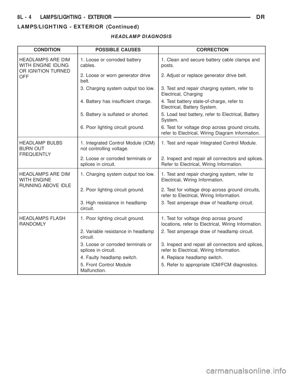
HEADLAMP DIAGNOSIS
CONDITION POSSIBLE CAUSES CORRECTION
HEADLAMPS ARE DIM
WITH ENGINE IDLING
OR IGNITION TURNED
OFF1. Loose or corroded battery
cables.1. Clean and secure battery cable clamps and
posts.
2. Loose or worn generator drive
belt.2. Adjust or replace generator drive belt.
3. Charging system output too low. 3. Test and repair charging system, refer to
Electrical, Charging
4. Battery has insufficient charge. 4. Test battery state-of-charge, refer to
Electrical, Battery System.
5. Battery is sulfated or shorted. 5. Load test battery, refer to Electrical, Battery
System.
6. Poor lighting circuit ground. 6. Test for voltage drop across ground circuits,
refer to Electrical, Wiring Diagram Information.
HEADLAMP BULBS
BURN OUT
FREQUENTLY1. Integrated Control Module (ICM)
not controlling voltage.1. Test and repair Integrated Control Module.
2. Loose or corroded terminals or
splices in circuit.2. Inspect and repair all connectors and splices.
Refer to Electrical, Wiring Information.
HEADLAMPS ARE DIM
WITH ENGINE
RUNNING ABOVE IDLE1. Charging system output too low. 1. Test and repair charging system, refer to
Electrical, Wiring Information.
2. Poor lighting circuit ground. 2. Test for voltage drop across ground circuits,
refer to Electrical, Wiring Information.
3. High resistance in headlamp
circuit.3. Test amperage draw of headlamp circuit.
HEADLAMPS FLASH
RANDOMLY1. Poor lighting circuit ground. 1. Test for voltage drop across ground
locations, refer to Electrical, Wiring Information.
2. Variable resistance in headlamp
circuit.2. Test amperage draw of headlamp circuit.
3. Loose or corroded terminals or
splices in circuit.3. Inspect and repair all connectors and splices,
refer to Electrical, Wiring Information.
4. Faulty headlamp switch. 4. Replace headlamp switch.
5. Front Control Module
Malfunction.5. Refer to appropriate ICM/FCM diagnostics.
8L - 4 LAMPS/LIGHTING - EXTERIORDR
LAMPS/LIGHTING - EXTERIOR (Continued)
Page 542 of 2895

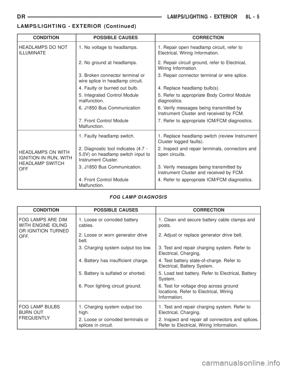
CONDITION POSSIBLE CAUSES CORRECTION
HEADLAMPS DO NOT
ILLUMINATE1. No voltage to headlamps. 1. Repair open headlamp circuit, refer to
Electrical, Wiring Information.
2. No ground at headlamps. 2. Repair circuit ground, refer to Electrical,
Wiring Information.
3. Broken connector terminal or
wire splice in headlamp circuit.3. Repair connector terminal or wire splice.
4. Faulty or burned out bulb. 4. Replace headlamp bulb(s).
5. Integrated Control Module
malfunction.5. Refer to appropriate Body Control Module
diagnostics.
6. J1850 Bus Communication 6. Verify messages being transmitted by
Instrument Cluster and received by FCM.
7. Front Control Module
Malfunction.7. Refer to appropriate ICM/FCM diagnostics.
HEADLAMPS ON WITH
IGNITION IN RUN, WITH
HEADLAMP SWITCH
OFF1. Faulty headlamp switch. 1. Replace headlamp switch (review Instrument
Cluster logged faults).
2. Diagnostic tool indicates (4.7 -
5.0V) on headlamp switch input to
Instrument Cluster.2. Inspect and repair terminals, connectors and
open circuits.
3. J1850 Bus Communication. 3. Verify messages being transmitted by
Instrument Cluster and received by FCM.
4. Front Control Module
Malfunction.4. Refer to appropriate ICM/FCM diagnostics.
FOG LAMP DIAGNOSIS
CONDITION POSSIBLE CAUSES CORRECTION
FOG LAMPS ARE DIM
WITH ENGINE IDLING
OR IGNITION TURNED
OFF.1. Loose or corroded battery
cables.1. Clean and secure battery cable clamps and
posts.
2. Loose or worn generator drive
belt.2. Adjust or replace generator drive belt.
3. Charging system output too low. 3. Test and repair charging system. Refer to
Electrical, Charging,
4. Battery has insufficient charge. 4. Test battery state-of-charge. Refer to
Electrical, Battery System.
5. Battery is sulfated or shorted. 5. Load test battery. Refer to Electrical, Battery
System.
6. Poor lighting circuit ground. 6. Test for voltage drop across ground
locations. Refer to Electrical, Wiring
Information.
FOG LAMP BULBS
BURN OUT
FREQUENTLY1. Charging system output too
high.1. Test and repair charging system. Refer to
Electrical, Charging.
2. Loose or corroded terminals or
splices in circuit.2. Inspect and repair all connectors and splices.
Refer to Electrical, Wiring Information.
DRLAMPS/LIGHTING - EXTERIOR 8L - 5
LAMPS/LIGHTING - EXTERIOR (Continued)
Page 545 of 2895

OPERATION
The backup lamp switch controls the flow of bat-
tery voltage to the backup lamp bulbs through an
output on the back-up lamp feed circuit. The switch
plunger is mechanically actuated by the gearshift
mechanism within the transmission, which will
depress the switch plunger and close the switch con-
tacts whenever the reverse gear has been selected.
The switch receives battery voltage through a fuse in
the Integrated Power Module (IPM) on a fused igni-
tion switch output (run) circuit whenever the ignition
switch is in the On position. A take out of the engine
wire harness connects the backup lamp switch to the
vehicle electrical system. The backup lamp switch
and circuits can be tested using conventional diag-
nostic tools and methods.
DIAGNOSIS AND TESTING - BACKUP LAMP
SWITCH
(1) Disconnect and isolate the battery negative
cable.
(2) Raise and support the vehicle.
(3) Locate and disconnect the engine wire harness
connector for the backup lamp switch.
(4) Check for continuity between the two terminal
pins in the backup lamp switch connector.
(a) With the gear selector lever in the Reverse
position, there should be continuity.
(b) With the gear selector lever in any position
other than Reverse, there should be no continuity.
BRAKE LAMP
REMOVAL
(1) Disconnect and isolate the negative battery
cable.
(2) Remove the tail lamp unit (Refer to 8 - ELEC-
TRICAL/LAMPS/LIGHTING - EXTERIOR/TAIL
LAMP UNIT - REMOVAL).
(3) Remove the bulb back plate from the tail lamp
unit.
(4) Remove the bulb from the back plate.
INSTALLATION
(1) Install the bulb into the back plate.
(2) Install the bulb back plate to the tail lamp
unit.
(3) Install the tail lamp unit (Refer to 8 - ELEC-
TRICAL/LAMPS/LIGHTING - EXTERIOR/TAIL
LAMP UNIT - INSTALLATION).
(4) Connect the negative battery cable.
BRAKE LAMP SWITCH
DESCRIPTION
The plunger type brake lamp switch is mounted on
a bracket attached to the base of the steering col-
umn, under the instrument panel.
CAUTION: The switch can only be adjusted during
initial installation. If the switch is not adjusted prop-
erly a new switch must be installed.
OPERATION
The brake lamp switch is hard wired to the Center
High Mount Stop Lamp (CHMSL) and also moni-
tored by the Instrument Cluster for use by the brake
lamp, speed control brake sensor circuits and elec-
tronic brake distribution (EBD). The brake lamp cir-
cuit is open until the plunger is depressed. The speed
control and brake sensor circuits are closed until the
plunger is depressed. When the brake lamp switch
transitions, the CHMSL transitions and instrument
cluster transmits a brake applied/released message
on the bus. The Integrated Power Module (IPM) will
then transition the brake lamps.
When the brake light switch is activated, the Pow-
ertrain Control Module (PCM) receives an input indi-
cating that the brakes are being applied. After
receiving this input, the PCM maintains idle speed to
a scheduled rpm through control of the Idle Air Con-
trol (IAC) motor. The brake switch input is also used
to disable vent and vacuum solenoid output signals
to the speed control servo.
Fig. 1 Backup Lamp Switch - Typical
1 - MANUAL TRANSMISSION
2 - BACKUP LAMP SWITCH
3 - ENGINE WIRE HARNESS
8L - 8 LAMPS/LIGHTING - EXTERIORDR
BACKUP LAMP SWITCH (Continued)
Page 550 of 2895

(3) Resistance between terminals 85 and 86 (elec-
tromagnet) should be 75 8 ohms. If OK, go to Step
4. If not OK, replace the faulty relay.
(4) Connect a battery to terminals 85 and 86.
There should now be continuity between terminals
30 and 87, and no continuity between terminals 87A
and 30. If OK, reinstall the relay and use a DRBIIIt
scan tool to perform further testing. Refer to the
appropriate diagnostic information.
REMOVAL
WARNING: ON VEHICLES EQUIPPED WITH AIR-
BAGS, DISABLE THE SUPPLEMENTAL RESTRAINT
SYSTEM BEFORE ATTEMPTING ANY STEERING
WHEEL, STEERING COLUMN, DRIVER AIRBAG,
PASSENGER AIRBAG, SEAT BELT TENSIONER,
FRONT IMPACT SENSORS, SIDE CURTAIN AIRBAG,
OR INSTRUMENT PANEL COMPONENT DIAGNOSIS
OR SERVICE. DISCONNECT AND ISOLATE THE
BATTERY NEGATIVE (GROUND) CABLE, THEN
WAIT TWO MINUTES FOR THE SYSTEM CAPACI-
TOR TO DISCHARGE BEFORE PERFORMING FUR-
THER DIAGNOSIS OR SERVICE. THIS IS THE ONLY
SURE WAY TO DISABLE THE SUPPLEMENTAL
RESTRAINT SYSTEM. FAILURE TO TAKE THE
PROPER PRECAUTIONS COULD RESULT IN ACCI-
DENTAL AIRBAG DEPLOYMENT AND POSSIBLE
PERSONAL INJURY.
(1) Disconnect and isolate the battery negative
cable.
(2) Remove the cover for the Power Distribution
Center (PDC).
(3) Remove the front fog lamp relay by grasping it
firmly and pulling it straight out from the receptacle
in the PDC.
INSTALLATION
WARNING: ON VEHICLES EQUIPPED WITH AIR-
BAGS, DISABLE THE SUPPLEMENTAL RESTRAINT
SYSTEM BEFORE ATTEMPTING ANY STEERING
WHEEL, STEERING COLUMN, DRIVER AIRBAG,
PASSENGER AIRBAG, SEAT BELT TENSIONER,
FRONT IMPACT SENSORS, SIDE CURTAIN AIRBAG,
OR INSTRUMENT PANEL COMPONENT DIAGNOSIS
OR SERVICE. DISCONNECT AND ISOLATE THE
BATTERY NEGATIVE (GROUND) CABLE, THEN
WAIT TWO MINUTES FOR THE SYSTEM CAPACI-
TOR TO DISCHARGE BEFORE PERFORMING FUR-
THER DIAGNOSIS OR SERVICE. THIS IS THE ONLY
SURE WAY TO DISABLE THE SUPPLEMENTAL
RESTRAINT SYSTEM. FAILURE TO TAKE THE
PROPER PRECAUTIONS COULD RESULT IN ACCI-
DENTAL AIRBAG DEPLOYMENT AND POSSIBLE
PERSONAL INJURY.(1) Position the front fog lamp relay to the proper
receptacle in the Power Distribution Center (PDC).
(2) Align the front fog lamp relay terminals with
the terminal cavities in the PDC.
(3) Press firmly and evenly on the top of the front
fog lamp relay until the terminals are fully seated in
the PDC.
(4) Reconnect the battery negative cable.
HAZARD SWITCH
DESCRIPTION
The hazard switch is activated by a push button
located in the multifunction switch on the top of the
steering column between the steering wheel and
instrument cluster.
The hazard warning system allows the vehicle
operator to provide other vehicle operators in the
near proximity an optical indication that the vehicle
is disabled or an obstacle to traffic flow. The hazard
warning system has battery voltage at all times,
regardless of ignition position.
OPERATION
The instrument cluster monitors the multiplexed
multifunction switch operation. When the hazard
warning switch is activated, the instrument cluster
will send a J1850 bus message to the Front Control
Module (FCM), then activate the two turn signal indi-
cators and audible click in the instrument cluster.
The FCM will then activate the necessary relays in
the Power Distribution Center (PDC) to begin flash-
ing both the front and rear turn signal indicator
lamps.
HEADLAMP
REMOVAL
(1) Disconnect and isolate the negitive battery
cable.
(2) Remove the headlamp unit (Refer to 8 - ELEC-
TRICAL/LAMPS/LIGHTING - EXTERIOR/HEAD-
LAMP UNIT - REMOVAL).
(3) Seperate the socket from the headlamp unit.
INSTALLATION
CAUTION: Do Not Touch the bulb glass with fingers
or other oily surfaces. Reduced bulb life will result.
(1) Install the socket into the headlamp unit.
(2) Install the headlamp unit (Refer to 8 - ELEC-
TRICAL/LAMPS/LIGHTING - EXTERIOR/HEAD-
LAMP UNIT - INSTALLATION).
(3) Connect the negitive battery cable.
DRLAMPS/LIGHTING - EXTERIOR 8L - 13
FOG LAMP RELAY (Continued)
Page 561 of 2895

LAMPS/LIGHTING - INTERIOR
TABLE OF CONTENTS
page page
DOME LAMP
DESCRIPTION.........................24
OPERATION...........................24
REMOVAL.............................24
INSTALLATION.........................24
DOOR AJAR SWITCH
DESCRIPTION.........................25
OPERATION...........................25GLOVE BOX LAMP/SWITCH
REMOVAL.............................25
INSTALLATION.........................25
READING LAMP
DESCRIPTION.........................26
OPERATION...........................26
REMOVAL.............................26
INSTALLATION.........................26
DOME LAMP
DESCRIPTION
The dome lamp is controlled by the instrument
cluster which provides power at all times, regardless
of the ignition switch position. The ground circuit for
the lamp is switched through the integral dome lamp
switch or through the door ajar switches via the
instrument cluster.
The dome lamp lens and bulb are available for ser-
vice replacement. If either of the lamp switch or bulb
holders is faulty or damaged, the dome lamp assem-
bly must be replaced.
For service of the dome lamp bulb, refer to the
appropriate wiring information.
OPERATION
The dome lamp is activated by the door ajar
switches via the instrument cluster. When all of the
doors are closed, the lamp can be activated by
depressing the lens. When any door is open, depress-
ing the lamp lense to activate the lamp switch will
not turn the lamps off.
The instrument cluster monitors the door ajar
switches. When a door is open the instrument cluster
grounds the low side drivers to turn on the lamp.
Upon closing all doors, the instrument cluster ini-
tiates a 30 second timer. If any of the doors are
opened during the ªtime outº cycle, the instrument
cluster will reset the timer until all doors are closed.
The instrument cluster will faid to off when the doors
are closed and the ignition is turned ON, the time
out expires or the power locks are activated.
REMOVAL
(1) Using a small flat blade, pry the left side (driv-
er's side) of the dome lamp lens downward from
dome lamp.(2) Allow the lens to hang down (Fig. 1), this will
disengage the right side of the lamp (passenger's
side) from the headliner.
(3) Pull the right side of the lamp down and slide
the lamp to the right (Fig. 2).
(4) Separate the lamp from the headliner.
(5) Disengage dome lamp wire connector from body
wire harness.
(6) Separate dome lamp from vehicle.
INSTALLATION
(1) Position dome lamp at headliner.
(2) Connect dome lamp wire connector to body
wire harness.
(3) Position the left side of the lamp in the head-
liner opening and slide lamp to the left (Fig. 1).
(4) Push the right side of the lamp in the head-
liner opening and push the lamp lens up into the
lamp to secure (Fig. 1).
Fig. 1 Dome Lamp Lens
1 - HEADLINER
2 - CONNECTOR
3 - DOME LAMP
4 - LENS
5 - BULB
8L - 24 LAMPS/LIGHTING - INTERIORDR
Page 563 of 2895

(4) Push the glove box lamp and switch unit into
the hole in the mounting bracket on the instrument
panel glove box opening upper reinforcement.
(5) Install the glove box onto the instrument panel.
(Refer to 23 - BODY/INSTRUMENT PANEL/GLOVE
BOX - INSTALLATION) for the procedures.
(6) Close the glove box.
(7) Reconnect the battery negative cable.
READING LAMP
DESCRIPTION
The overhead console in this vehicle is equipped
with two individual reading and courtesy lamps. The
lamp lenses are the only visible components of these
lamps. Each lamp has its own switch, bulb, reflector
and lens within the overhead console.
The overhead console reading and courtesy lamps
are controlled by the instrument cluster which pro-
vides power at all times, regardless of the ignition
switch position. The ground circuit for the lamps is
switched through the integral reading and courtesy
lamp switches or through the door ajar switches.
Each lamp is designed and aimed to provide illumi-
nation that will be directed only to that side of the
vehicle on which the lamp is located.
The reading and courtesy lamp lenses and bulbs
are available for service replacement. The reading
and courtesy lamp switches, bulb holders and wiring
are only available as part of the overhead console
wire harness. If either of the lamp switches or bulb
holders is faulty or damaged, the entire overhead
console wire harness assembly must be replaced.
For service of the reading and courtesy lamp bulbs,
refer to the appropriate wiring information.
OPERATION
All reading and courtesy lamps located in the over-
head console are activated by the door ajar switches
via the instrument cluster. When all of the doors are
closed, these lamps can be individually activated by
depressing the corresponding lens. When any door is
open, depressing the lamp lenses to activate the lamp
switches will not turn the lamps off.
The instrument cluster monitors the door ajar
switches. When a door is open the instrument cluster
grounds the low side drivers to turn on the lamps.
Upon closing all doors, the instrument cluster ini-
tiates a 30 second timer. If any of the doors are
opened during the ªtime outº cycle, the instrument
cluster will reset the timer until all doors are closed.
The instrument cluster will faid to off when the doors
are closed and the ignition is turned ON, the time
out expires or the power locks are activated.
REMOVAL
(1) Disconnect and isolate the battery negative
cable.
(2) Insert a long, narrow, flat-bladed tool between
the curved (outboard) edge of the reading and cour-
tesy lamp lens and the overhead console housing
(Fig. 4).
(3) Gently pry inward and downward against the
lens until the latch tab in the center of the outboard
edge of the reading and courtesy lamp lens is disen-
gaged from the overhead console housing.
(4)
Pull firmly on the lens toward the outboard side
of the vehicle to disengage the two pivot tabs on the
inboard edge of the reading and courtesy lamp lens
are disengaged from the overhead console housing.
(5) Remove the reading and courtesy lamp lens
from the overhead console housing.
INSTALLATION
(1) Position the reading and courtesy lamp lens
onto the overhead console housing.
(2) Align the two pivot tabs on the inboard edge of
the reading and courtesy lamp lens with the two
pivot holes in the overhead console housing.
(3) Push firmly on the lens toward the inboard
side of the vehicle to insert the two pivot tabs on the
inboard edge of the reading and courtesy lamp lens
into the two pivot holes in the overhead console hous-
ing.
(4) Pivot the lens back up into position and press
upward firmly until the latch tab in the center of the
outboard edge of the reading and courtesy lamp lens
snaps back into the overhead console housing.
(5) Reconnect the battery negative cable.
Fig. 4 Overhead Console Reading Lamp Bulb
Removal
1 - LENS
2 - FLAT BLADE
3 - CONSOLE
8L - 26 LAMPS/LIGHTING - INTERIORDR
GLOVE BOX LAMP/SWITCH (Continued)