2003 DODGE RAM electrical
[x] Cancel search: electricalPage 543 of 2895
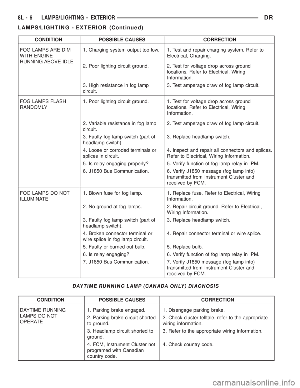
CONDITION POSSIBLE CAUSES CORRECTION
FOG LAMPS ARE DIM
WITH ENGINE
RUNNING ABOVE IDLE1. Charging system output too low. 1. Test and repair charging system. Refer to
Electrical, Charging.
2. Poor lighting circuit ground. 2. Test for voltage drop across ground
locations. Refer to Electrical, Wiring
Information.
3. High resistance in fog lamp
circuit.3. Test amperage draw of fog lamp circuit.
FOG LAMPS FLASH
RANDOMLY1. Poor lighting circuit ground. 1. Test for voltage drop across ground
locations. Refer to Electrical, Wiring
Information.
2. Variable resistance in fog lamp
circuit.2. Test amperage draw of fog lamp circuit.
3. Faulty fog lamp switch (part of
headlamp switch).3. Replace headlamp switch.
4. Loose or corroded terminals or
splices in circuit.4. Inspect and repair all connectors and splices.
Refer to Electrical, Wiring Information.
5. Is relay engaging properly? 5. Verify function of fog lamp relay in IPM.
6. J1850 Bus Communication. 6. Verify J1850 message (fog lamp info)
transmitted from Instrument Cluster and
received by FCM.
FOG LAMPS DO NOT
ILLUMINATE1. Blown fuse for fog lamp. 1. Replace fuse. Refer to Electrical, Wiring
Information.
2. No ground at fog lamps. 2. Repair circuit ground. Refer to Electrical,
Wiring Information.
3. Faulty fog lamp switch (part of
headlamp switch).3. Replace headlamp switch.
4. Broken connector terminal or
wire splice in fog lamp circuit.4. Repair connector terminal or wire splice.
5. Faulty or burned out bulb. 5. Replace bulb.
6. Is relay engaging? 6. Verify function of fog lamp relay in IPM.
7. J1850 Bus Communication. 7. Verify J1850 message (fog lamp info)
transmitted from Instrument Cluster and
received by FCM.
DAYTIME RUNNING LAMP (CANADA ONLY) DIAGNOSIS
CONDITION POSSIBLE CAUSES CORRECTION
DAYTIME RUNNING
LAMPS DO NOT
OPERATE1. Parking brake engaged. 1. Disengage parking brake.
2. Parking brake circuit shorted
to ground.2. Check cluster telltale, refer to the appropriate
wiring information.
3. Headlamp circuit shorted to
ground.3. Refer to the appropriate wiring information.
4. FCM, Instrument Cluster not
programed with Canadian
country code.4. Check country code.
8L - 6 LAMPS/LIGHTING - EXTERIORDR
LAMPS/LIGHTING - EXTERIOR (Continued)
Page 545 of 2895

OPERATION
The backup lamp switch controls the flow of bat-
tery voltage to the backup lamp bulbs through an
output on the back-up lamp feed circuit. The switch
plunger is mechanically actuated by the gearshift
mechanism within the transmission, which will
depress the switch plunger and close the switch con-
tacts whenever the reverse gear has been selected.
The switch receives battery voltage through a fuse in
the Integrated Power Module (IPM) on a fused igni-
tion switch output (run) circuit whenever the ignition
switch is in the On position. A take out of the engine
wire harness connects the backup lamp switch to the
vehicle electrical system. The backup lamp switch
and circuits can be tested using conventional diag-
nostic tools and methods.
DIAGNOSIS AND TESTING - BACKUP LAMP
SWITCH
(1) Disconnect and isolate the battery negative
cable.
(2) Raise and support the vehicle.
(3) Locate and disconnect the engine wire harness
connector for the backup lamp switch.
(4) Check for continuity between the two terminal
pins in the backup lamp switch connector.
(a) With the gear selector lever in the Reverse
position, there should be continuity.
(b) With the gear selector lever in any position
other than Reverse, there should be no continuity.
BRAKE LAMP
REMOVAL
(1) Disconnect and isolate the negative battery
cable.
(2) Remove the tail lamp unit (Refer to 8 - ELEC-
TRICAL/LAMPS/LIGHTING - EXTERIOR/TAIL
LAMP UNIT - REMOVAL).
(3) Remove the bulb back plate from the tail lamp
unit.
(4) Remove the bulb from the back plate.
INSTALLATION
(1) Install the bulb into the back plate.
(2) Install the bulb back plate to the tail lamp
unit.
(3) Install the tail lamp unit (Refer to 8 - ELEC-
TRICAL/LAMPS/LIGHTING - EXTERIOR/TAIL
LAMP UNIT - INSTALLATION).
(4) Connect the negative battery cable.
BRAKE LAMP SWITCH
DESCRIPTION
The plunger type brake lamp switch is mounted on
a bracket attached to the base of the steering col-
umn, under the instrument panel.
CAUTION: The switch can only be adjusted during
initial installation. If the switch is not adjusted prop-
erly a new switch must be installed.
OPERATION
The brake lamp switch is hard wired to the Center
High Mount Stop Lamp (CHMSL) and also moni-
tored by the Instrument Cluster for use by the brake
lamp, speed control brake sensor circuits and elec-
tronic brake distribution (EBD). The brake lamp cir-
cuit is open until the plunger is depressed. The speed
control and brake sensor circuits are closed until the
plunger is depressed. When the brake lamp switch
transitions, the CHMSL transitions and instrument
cluster transmits a brake applied/released message
on the bus. The Integrated Power Module (IPM) will
then transition the brake lamps.
When the brake light switch is activated, the Pow-
ertrain Control Module (PCM) receives an input indi-
cating that the brakes are being applied. After
receiving this input, the PCM maintains idle speed to
a scheduled rpm through control of the Idle Air Con-
trol (IAC) motor. The brake switch input is also used
to disable vent and vacuum solenoid output signals
to the speed control servo.
Fig. 1 Backup Lamp Switch - Typical
1 - MANUAL TRANSMISSION
2 - BACKUP LAMP SWITCH
3 - ENGINE WIRE HARNESS
8L - 8 LAMPS/LIGHTING - EXTERIORDR
BACKUP LAMP SWITCH (Continued)
Page 547 of 2895
INSTALLATION
(1) Press and hold the brake pedal down.
(2) Align the tab on thenewswitch with the notch
in the switch bracket. Insert the switch in the
bracket and turn it clockwise about 30É to lock it in
place.
(3) Connect the harness wires to the switch.
(4) Release the brake pedal.
(5) Move the release lever on the switch parallel
with the connector to engage the switch plunger. The
switch is now adjusted andcan notbe adjusted
again.
CENTER HIGH MOUNTED
STOP LAMP
REMOVAL
(1) Disconnect and isolate the battery negative
cable.
(2) Remove the CHMSL from the roof panel. Refer
to (Refer to 8 - ELECTRICAL/LAMPS/LIGHTING -
EXTERIOR/CENTER HIGH MOUNTED STOP
LAMP UN - REMOVAL).
(3) Turn the bulb socket 1/4 turn counterclockwise.
(4) Separate the socket from the lamp.
(5) Remove the bulb.
INSTALLATION
(1) Position the bulb in the socket and press into
place.
(2) Position the socket in the lamp.
(3) Turn the bulb socket 1/4 turn clockwise.
(4) Install the CHMSL. Refer to (Refer to 8 -
ELECTRICAL/LAMPS/LIGHTING - EXTERIOR/
CENTER HIGH MOUNTED STOP LAMP UN -
INSTALLATION).
(5) Connect the battery negative cable.
CENTER HIGH MOUNTED
STOP LAMP UNIT
REMOVAL
(1) Disconnect and isolate the battery negative
cable.
(2) Remove screws holding CHMSL to roof panel
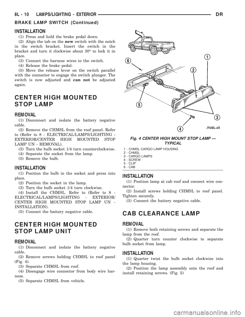
(Fig. 4).
(3) Separate CHMSL from roof.
(4) Disengage wire connector from body wire har-
ness.
(5) Separate CHMSL from vehicle.
INSTALLATION
(1) Position lamp at cab roof and connect wire con-
nector.
(2) Install screws holding CHMSL to roof panel.
Tighten securely.
(3) Connect the battery negative cable.
CAB CLEARANCE LAMP
REMOVAL
(1) Remove both retaining screws and separate the
lamp from the roof.
(2) Quarter turn counter clockwise to separate
bulb socket from lamp.
INSTALLATION
(1) Quarter twist the bulb socket clockwise into
the lamp housing.
(2) Position the lamp assembly onto the roof and
install retaining screws. (Fig. 5)
Fig. 4 CENTER HIGH MOUNT STOP LAMP Ð
TYPICAL
1 - CHMSL CARGO LAMP HOUSING
2 - CHMSL
3 - CARGO LAMPS
4 - SCREW
5 - CLIP
6 - CAB
8L - 10 LAMPS/LIGHTING - EXTERIORDR
BRAKE LAMP SWITCH (Continued)
Page 549 of 2895

(ISO) micro relay (Fig. 7). Relays conforming to the
ISO specifications have common physical dimensions,
current capacities, terminal patterns, and terminal
functions. The relay is contained within a small, rect-
angular, molded plastic housing and is connected to
all of the required inputs and outputs by five integral
male spade-type terminals that extend from the bot-
tom of the relay base.
The front fog lamp relay cannot be adjusted or
repaired and, if faulty or damaged, the unit must be
replaced.
OPERATION
The front fog lamp relay is an electromechanical
switch that uses a low current input from the Front
Control Module (FCM) to control a high current out-
put to the front fog lamps. The movable common feed
contact point is held against the fixed normally
closed contact point by spring pressure. When the
relay coil is energized, an electromagnetic field is
produced by the coil windings. This electromagnetic
field draws the movable relay contact point away
from the fixed normally closed contact point, and
holds it against the fixed normally open contact
point. When the relay coil is de-energized, spring
pressure returns the movable contact point back
against the fixed normally closed contact point. A
resistor is connected in parallel with the relay coil in
the relay, and helps to dissipate voltage spikes and
electromagnetic interference that can be generated as
the electromagnetic field of the relay coil collapses.
The front fog lamp relay terminals are connected
to the vehicle electrical system through a connector
receptacle in the Power Distribution Center (PDC).
The inputs and outputs of the front fog lamp relay
include:
²Common Feed Terminal- The common feed
terminal (30) receives battery voltage at all times
from a fuse in the PDC through a fused B(+) circuit.
²Coil Ground Terminal- The coil ground termi-
nal (85) is connected to a control output of the Front
Control Module (FCM) through a front fog lamp relay
control circuit. The FCM controls front fog lamp oper-
ation by controlling a ground path through this cir-
cuit.
²Coil Battery Terminal- The coil battery ter-
minal (86) receives battery voltage at all times from
a fuse in the PDC through a fused B(+) circuit.
²Normally Open Terminal- The normally open
terminal (87) is connected to the front fog lamps
through a front fog lamp relay output circuit and
provides battery voltage to the front fog lamps when-
ever the relay is energized.
²Normally Closed Terminal- The normally
closed terminal (87A) is not connected in this appli-
cation.The front fog lamp relay can be diagnosed using
conventional diagnostic tools and methods.
DIAGNOSIS AND TESTING - FRONT FOG LAMP
RELAY
The front fog lamp relay (Fig. 8) is located in the
Power Distribution Center in the engine compart-
ment. Refer to the appropriate wiring information.
WARNING: ON VEHICLES EQUIPPED WITH AIR-
BAGS, DISABLE THE SUPPLEMENTAL RESTRAINT
SYSTEM BEFORE ATTEMPTING ANY STEERING
WHEEL, STEERING COLUMN, DRIVER AIRBAG,
PASSENGER AIRBAG, SEAT BELT TENSIONER,
FRONT IMPACT SENSORS, SIDE CURTAIN AIRBAG,
OR INSTRUMENT PANEL COMPONENT DIAGNOSIS
OR SERVICE. DISCONNECT AND ISOLATE THE
BATTERY NEGATIVE (GROUND) CABLE, THEN
WAIT TWO MINUTES FOR THE SYSTEM CAPACI-
TOR TO DISCHARGE BEFORE PERFORMING FUR-
THER DIAGNOSIS OR SERVICE. THIS IS THE ONLY
SURE WAY TO DISABLE THE SUPPLEMENTAL
RESTRAINT SYSTEM. FAILURE TO TAKE THE
PROPER PRECAUTIONS COULD RESULT IN ACCI-
DENTAL AIRBAG DEPLOYMENT AND POSSIBLE
PERSONAL INJURY.
(1) Remove the front fog lamp relay from the PDC.
(Refer to 8 - ELECTRICAL/LAMPS/LIGHTING -
EXTERIOR/FRONT FOG LAMP RELAY - REMOV-
AL).
(2) A relay in the de-energized position should
have continuity between terminals 87A and 30, and
no continuity between terminals 87 and 30. If OK, go
to Step 3. If not OK, replace the faulty relay.
Fig. 8 ISO Micro Relay
30 - COMMON FEED
85 - COIL GROUND
86 - COIL BATTERY
87 - NORMALLY OPEN
87A - NORMALLY CLOSED
8L - 12 LAMPS/LIGHTING - EXTERIORDR
FOG LAMP RELAY (Continued)
Page 555 of 2895
lobe, pushing on the cancel actuator, returns the
switch to the OFF position.
OPERATION - TURN SIGNAL SYSTEM
The Instrument Cluster monitors the multiplexed
multifunction switch. In a turning event the Instru-
ment Cluster senses a change in the turn signal
lever and illuminates the appropriate turn signal
indicator. At the same time, the Instrument Cluster
will send a J1850 message on the PCI bus to the
Front Control Module (FCM). The FCM will respond
by activating the appropriate relay in the Power Dis-
tribution Center.
A chime will sound after the turn is completed if
vehicle has traveled a distance of approximately 1.0
mile and a speed of 15 mph, with the turn signal ON.
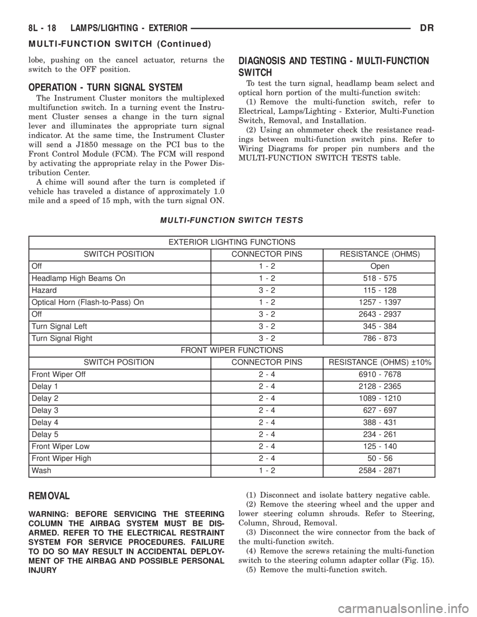
DIAGNOSIS AND TESTING - MULTI-FUNCTION
SWITCH
To test the turn signal, headlamp beam select and
optical horn portion of the multi-function switch:
(1) Remove the multi-function switch, refer to
Electrical, Lamps/Lighting - Exterior, Multi-Function
Switch, Removal, and Installation.
(2) Using an ohmmeter check the resistance read-
ings between multi-function switch pins. Refer to
Wiring Diagrams for proper pin numbers and the
MULTI-FUNCTION SWITCH TESTS table.
MULTI-FUNCTION SWITCH TESTS
EXTERIOR LIGHTING FUNCTIONS
SWITCH POSITION CONNECTOR PINS RESISTANCE (OHMS)
Off 1 - 2 Open
Headlamp High Beams On 1 - 2 518 - 575
Hazard 3 - 2 115 - 128
Optical Horn (Flash-to-Pass) On 1 - 2 1257 - 1397
Off 3 - 2 2643 - 2937
Turn Signal Left 3 - 2 345 - 384
Turn Signal Right 3 - 2 786 - 873
FRONT WIPER FUNCTIONS
SWITCH POSITION CONNECTOR PINS RESISTANCE (OHMS) 10%
Front Wiper Off 2 - 4 6910 - 7678
Delay 1 2 - 4 2128 - 2365
Delay 2 2 - 4 1089 - 1210
Delay 3 2 - 4 627 - 697
Delay 4 2 - 4 388 - 431
Delay 5 2 - 4 234 - 261
Front Wiper Low 2 - 4 125 - 140
Front Wiper High 2 - 4 50 - 56
Wash 1 - 2 2584 - 2871
REMOVAL
WARNING: BEFORE SERVICING THE STEERING
COLUMN THE AIRBAG SYSTEM MUST BE DIS-
ARMED. REFER TO THE ELECTRICAL RESTRAINT
SYSTEM FOR SERVICE PROCEDURES. FAILURE
TO DO SO MAY RESULT IN ACCIDENTAL DEPLOY-
MENT OF THE AIRBAG AND POSSIBLE PERSONAL
INJURY(1) Disconnect and isolate battery negative cable.
(2) Remove the steering wheel and the upper and
lower steering column shrouds. Refer to Steering,
Column, Shroud, Removal.
(3) Disconnect the wire connector from the back of
the multi-function switch.
(4) Remove the screws retaining the multi-function
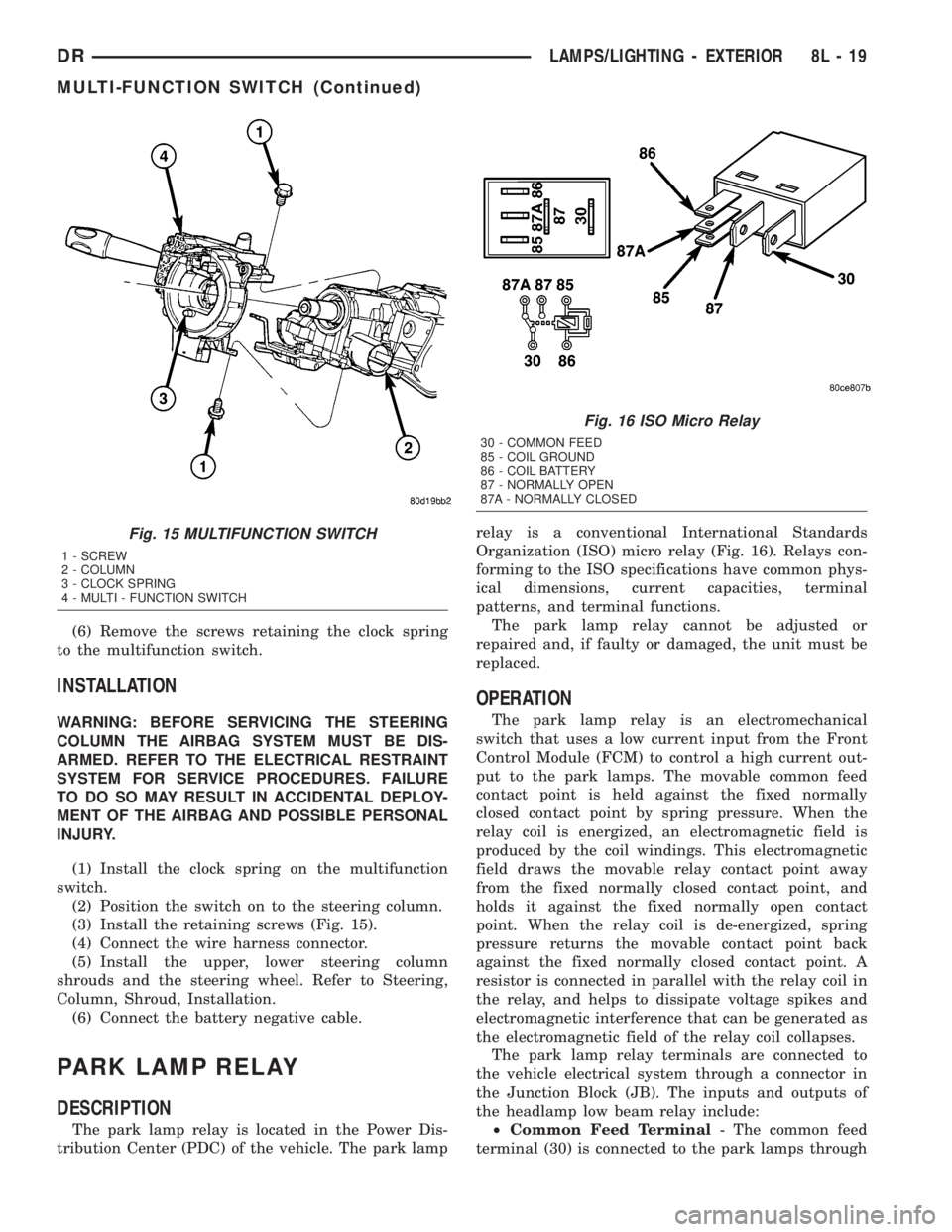
switch to the steering column adapter collar (Fig. 15).
(5) Remove the multi-function switch.
8L - 18 LAMPS/LIGHTING - EXTERIORDR
MULTI-FUNCTION SWITCH (Continued)
Page 556 of 2895
(6) Remove the screws retaining the clock spring
to the multifunction switch.
INSTALLATION
WARNING: BEFORE SERVICING THE STEERING
COLUMN THE AIRBAG SYSTEM MUST BE DIS-
ARMED. REFER TO THE ELECTRICAL RESTRAINT
SYSTEM FOR SERVICE PROCEDURES. FAILURE
TO DO SO MAY RESULT IN ACCIDENTAL DEPLOY-
MENT OF THE AIRBAG AND POSSIBLE PERSONAL
INJURY.
(1) Install the clock spring on the multifunction
switch.
(2) Position the switch on to the steering column.
(3) Install the retaining screws (Fig. 15).
(4) Connect the wire harness connector.
(5) Install the upper, lower steering column
shrouds and the steering wheel. Refer to Steering,
Column, Shroud, Installation.
(6) Connect the battery negative cable.
PARK LAMP RELAY
DESCRIPTION
The park lamp relay is located in the Power Dis-
tribution Center (PDC) of the vehicle. The park lamprelay is a conventional International Standards
Organization (ISO) micro relay (Fig. 16). Relays con-
forming to the ISO specifications have common phys-
ical dimensions, current capacities, terminal
patterns, and terminal functions.
The park lamp relay cannot be adjusted or
repaired and, if faulty or damaged, the unit must be
replaced.
OPERATION
The park lamp relay is an electromechanical
switch that uses a low current input from the Front
Control Module (FCM) to control a high current out-
put to the park lamps. The movable common feed
contact point is held against the fixed normally
closed contact point by spring pressure. When the
relay coil is energized, an electromagnetic field is
produced by the coil windings. This electromagnetic
field draws the movable relay contact point away
from the fixed normally closed contact point, and
holds it against the fixed normally open contact
point. When the relay coil is de-energized, spring
pressure returns the movable contact point back
against the fixed normally closed contact point. A
resistor is connected in parallel with the relay coil in
the relay, and helps to dissipate voltage spikes and
electromagnetic interference that can be generated as
the electromagnetic field of the relay coil collapses.
The park lamp relay terminals are connected to
the vehicle electrical system through a connector in
the Junction Block (JB). The inputs and outputs of
the headlamp low beam relay include:
²Common Feed Terminal- The common feed
terminal (30) is connected to the park lamps through
Fig. 15 MULTIFUNCTION SWITCH
1 - SCREW
2 - COLUMN
3 - CLOCK SPRING
4 - MULTI - FUNCTION SWITCH
Fig. 16 ISO Micro Relay
30 - COMMON FEED
85 - COIL GROUND
86 - COIL BATTERY
87 - NORMALLY OPEN
87A - NORMALLY CLOSED
DRLAMPS/LIGHTING - EXTERIOR 8L - 19
MULTI-FUNCTION SWITCH (Continued)
Page 558 of 2895

INSTALLATION
WARNING: ON VEHICLES EQUIPPED WITH AIR-
BAGS, DISABLE THE SUPPLEMENTAL RESTRAINT
SYSTEM BEFORE ATTEMPTING ANY STEERING
WHEEL, STEERING COLUMN, DRIVER AIRBAG,
PASSENGER AIRBAG, SEAT BELT TENSIONER,
FRONT IMPACT SENSORS, SIDE CURTAIN AIRBAG,
OR INSTRUMENT PANEL COMPONENT DIAGNOSIS
OR SERVICE. DISCONNECT AND ISOLATE THE
BATTERY NEGATIVE (GROUND) CABLE, THEN
WAIT TWO MINUTES FOR THE SYSTEM CAPACI-
TOR TO DISCHARGE BEFORE PERFORMING FUR-
THER DIAGNOSIS OR SERVICE. THIS IS THE ONLY
SURE WAY TO DISABLE THE SUPPLEMENTAL
RESTRAINT SYSTEM. FAILURE TO TAKE THE
PROPER PRECAUTIONS COULD RESULT IN ACCI-
DENTAL AIRBAG DEPLOYMENT AND POSSIBLE
PERSONAL INJURY.
(1) Position the park lamp relay to the proper
receptacle in the Power Distribution Center (PDC).
(2) Align the park lamp relay terminals with the
terminal cavities in the PDC.
(3) Press firmly and evenly on the top of the park
lamp relay until the terminals are fully seated in the
PDC.
(4) Install the PDC cover.
(5) Reconnect the battery negative cable.
PARK/TURN SIGNAL LAMP
REMOVAL
(1) Disconnect and isolate the negative battery
cable.
(2) Remove the headlamp unit.(Refer to 8 - ELEC-
TRICAL/LAMPS/LIGHTING - EXTERIOR/HEAD-
LAMP UNIT - REMOVAL).
(3) Seperate the socket from the headlamp unit.
(4) Release the bulb socket locking tabs and seper-
ate the bulb from the socket (Fig. 18).
INSTALLATION
(1) Install the bulb into the socket.
(2) Install the socket into the headlamp unit.
(3) Install the headlamp unit (Refer to 8 - ELEC-
TRICAL/LAMPS/LIGHTING - EXTERIOR/HEAD-
LAMP UNIT - INSTALLATION).
(4) Connect the negative battery cable.
TAIL LAMP
REMOVAL
(1) Disconnect and isolate the negative battery
cable.
(2) Remove the tail lamp unit (Refer to 8 - ELEC-
TRICAL/LAMPS/LIGHTING - EXTERIOR/TAIL
LAMP UNIT - REMOVAL).
(3) Remove the bulb back plate from the tail lamp
unit.
(4) Release the bulb locking tabs and remove the
bulb from the back plate (Fig. 18).
INSTALLATION
(1) Install the bulb into the back plate.
(2) Install the bulb back plate to the tail lamp
unit.
(3) Install the tail lamp unit (Refer to 8 - ELEC-
TRICAL/LAMPS/LIGHTING - EXTERIOR/TAIL
LAMP UNIT - INSTALLATION).
(4) Connect the negative battery cable.
TAIL LAMP UNIT
REMOVAL
(1) Lower the tail gate.
(2) Remove the screws
(3) Disengage the taillamp unit from the body
panel.
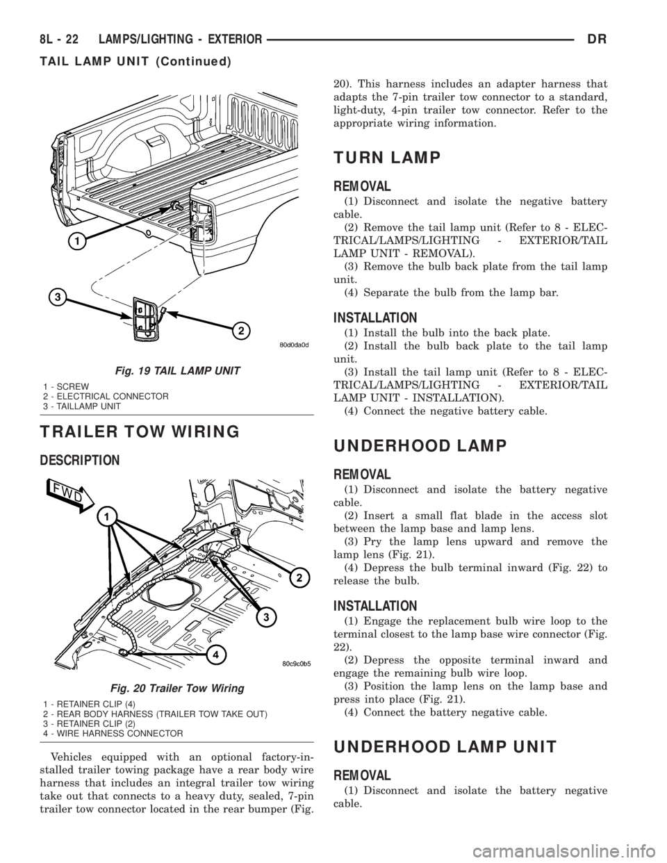
(4) Disconnect the electrical connector (Fig. 19).
INSTALLATION
(1) Connect the wiring harness connector.
(2) Position the taillamp unit into the body panel.
(3) Install the screws (Fig. 19).
Fig. 18 Pull Bulb From Socket
1 - SOCKET
2 - BULB
DRLAMPS/LIGHTING - EXTERIOR 8L - 21
PARK LAMP RELAY (Continued)
Page 559 of 2895
TRAILER TOW WIRING
DESCRIPTION
Vehicles equipped with an optional factory-in-
stalled trailer towing package have a rear body wire
harness that includes an integral trailer tow wiring
take out that connects to a heavy duty, sealed, 7-pin
trailer tow connector located in the rear bumper (Fig.20). This harness includes an adapter harness that
adapts the 7-pin trailer tow connector to a standard,
light-duty, 4-pin trailer tow connector. Refer to the
appropriate wiring information.
TURN LAMP
REMOVAL
(1) Disconnect and isolate the negative battery
cable.
(2) Remove the tail lamp unit (Refer to 8 - ELEC-
TRICAL/LAMPS/LIGHTING - EXTERIOR/TAIL
LAMP UNIT - REMOVAL).
(3) Remove the bulb back plate from the tail lamp
unit.
(4) Separate the bulb from the lamp bar.
INSTALLATION
(1) Install the bulb into the back plate.
(2) Install the bulb back plate to the tail lamp
unit.
(3) Install the tail lamp unit (Refer to 8 - ELEC-
TRICAL/LAMPS/LIGHTING - EXTERIOR/TAIL
LAMP UNIT - INSTALLATION).
(4) Connect the negative battery cable.
UNDERHOOD LAMP
REMOVAL
(1) Disconnect and isolate the battery negative
cable.
(2) Insert a small flat blade in the access slot
between the lamp base and lamp lens.
(3) Pry the lamp lens upward and remove the
lamp lens (Fig. 21).
(4) Depress the bulb terminal inward (Fig. 22) to
release the bulb.
INSTALLATION
(1) Engage the replacement bulb wire loop to the
terminal closest to the lamp base wire connector (Fig.
22).
(2) Depress the opposite terminal inward and
engage the remaining bulb wire loop.
(3) Position the lamp lens on the lamp base and
press into place (Fig. 21).
(4) Connect the battery negative cable.
UNDERHOOD LAMP UNIT
REMOVAL
(1) Disconnect and isolate the battery negative
cable.
Fig. 19 TAIL LAMP UNIT
1 - SCREW
2 - ELECTRICAL CONNECTOR
3 - TAILLAMP UNIT
Fig. 20 Trailer Tow Wiring
1 - RETAINER CLIP (4)
2 - REAR BODY HARNESS (TRAILER TOW TAKE OUT)
3 - RETAINER CLIP (2)
4 - WIRE HARNESS CONNECTOR
8L - 22 LAMPS/LIGHTING - EXTERIORDR
TAIL LAMP UNIT (Continued)